Author Archives: admin

Thermostats for Jaguar XK 120, 140 and 150

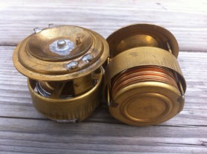
Original Jaguar XK 120, 140 and 150 thermostats.

Jaguar applied a  “Bellows”-type of thermostat with moving sleeve for all of their early XK engines. Jaguar initially used two different thermostat types, provided by either Smiths or British Thermostat where the latter type was stopped fairly soon after production of XK engines had started (see below). It remains unclear whether Smiths actually manufactured these products themselves or that they were purchased from Quinton-Brivec of Colwyn Bay (North-Wales): the construction of the two brands looks very similar.  AC of Dunstable (UK) was another manufacturer of thermostats, but with a clearly different construction.

The “British Thermostat” version was only fitted to Mark VII engines (numbers A2001 to A6000) and this thermostat is non-interchangeable with the Smiths version. The British Thermostat Company (also known as Teddington) manufactured all sorts of thermal control equipment, mainly based on the use of seamless metallic bellows. From 1934 onwards they also manufactured car thermostats in their factories at Windmill Road, Sunbury-on-Thames, Middlesex. Brtish Thermostats was the largest manufacturer of seamless metallic bellows in Europe and must have supplied many other manufacturers of these bellows type of thermostats.

British Thermostat seamless metalic bellows  
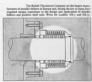
British Thermostat Co. was a large supplier of bellows         British Thermostat version was dome-shaped

The American Weston Miller Fulton (August 3, 1871 – May 16, 1946) is considered as the inventor of the bellows thermostat. The invention dates from the beginning of the 20th century, intended for use in heating systems. Around 1920 they were used to control radiator shutters in automobiles and in the Thirties as a thermostat for coolant in automobiles.  

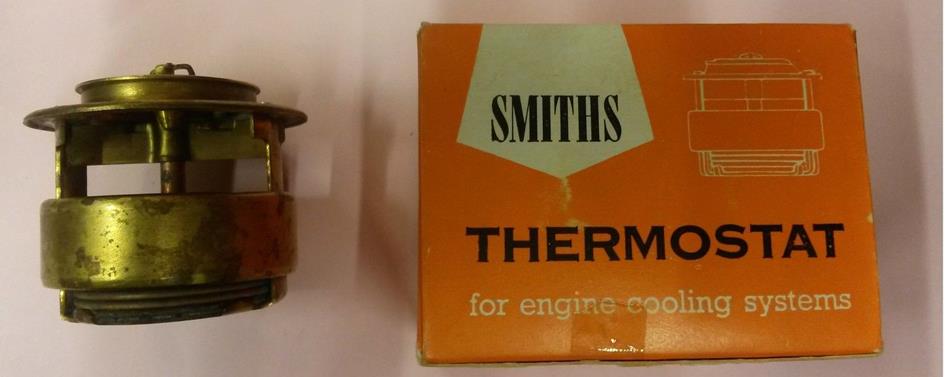
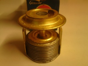
This type of  thermostat has a bellows made from e.g. berylium copper or bronze and has been filled with (liquid) alcohol or volatile oil. The set point temperature of the thermostat is determined by the boiling point of the used liquid in the bellows. The Bellows-type of thermostat relies therefor on expanding gases within the bellows when the temperature of the cooling fluid rises. The moving sleeve around the outside of the lower portion of the thermostat blocks off the bypass port in the inlet manifold to optimize the flow of coolant through the engine, once the engine has warmed up and the thermostat has fully opened. It will be clear that other types of thermostat without a moving sleeve will negatively affect the warming-up periode of the engine.

Reporduction thermostats China Detail bellows thermostat      
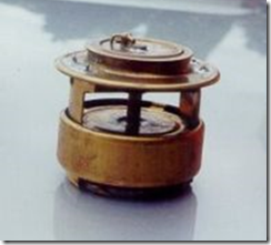
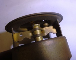
Original Smiths bellows-type thermostat                   Detail of “valve stem guide”

Bellows thermostats were first introduced in 1937 or 1938. A so called “bi-metal coiled system” (also supplied by Smiths) was applied before the introduction of Bellows thermostats.  Smiths bellows-type thermostat types were used on many cars throughout the 1940s and 1950s:  BMC, Ford, and many others used them for their engines with by-pass cooling system. Bellows thermostat production ceased in 1960 or 1961. The more typical wax pellet type thermostats were substituted.

Smiths bellows type thermostat on XK 120, XK 140 and XK 150.

Smiths initially offered three ranges of Bellows-type thermostat: the 43570 series, 43605 series and 43655 series. They all commenced opening at a certain temperature (indicated on the thermostat) and had fully opened about 15 to 20°C higher than the opening temperature. The maximum valve lift is about ⅜” (or 9,5 mm).

XK 120

The XK 120 without a heater used Jaguar code C.3731 which is a Smith’s thermostat bellows type, part number X.43655 with an opening temperature of 60 to 63°C and has fully opened at  80°C. The XK 120s provided with a heater used thermostat Jaguar code C.3731/1 or Smiths   X.43570/5 with an opening temperature of 73°C (163° F).  Smiths X.43570/28 seems to be identical to X.43570/5  but is probably a later version. The XK 120 thermostat is placed in the inlet of the radiator. The outer diameter of the thermostat is 54 mm (2⅛ inch). The sleeve measures 48mm in diameter and 15mm in depth.

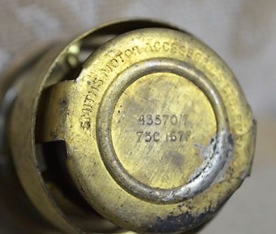
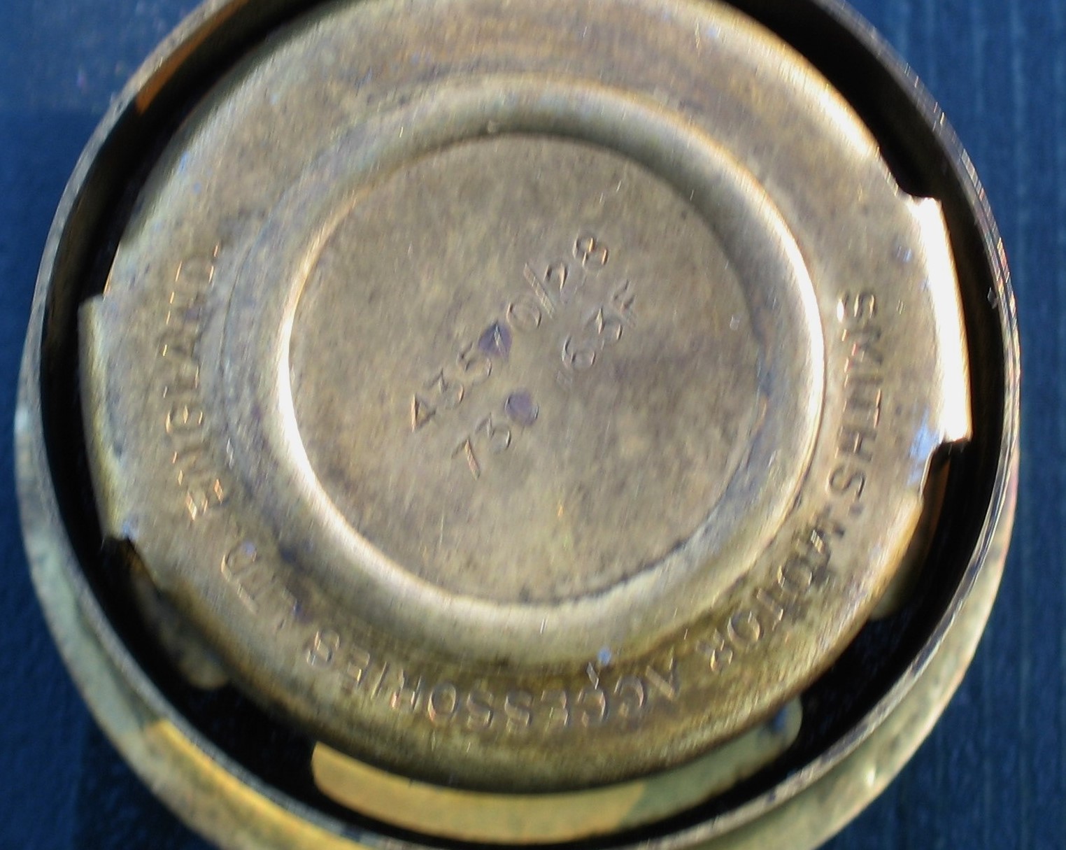
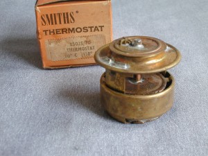
  Smiths X.43570/7 starts opening at 75 °C (167 °F)     Smiths thermostat X.43570/28 opens at 73 °C (163° F)
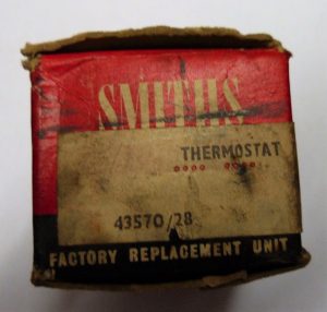
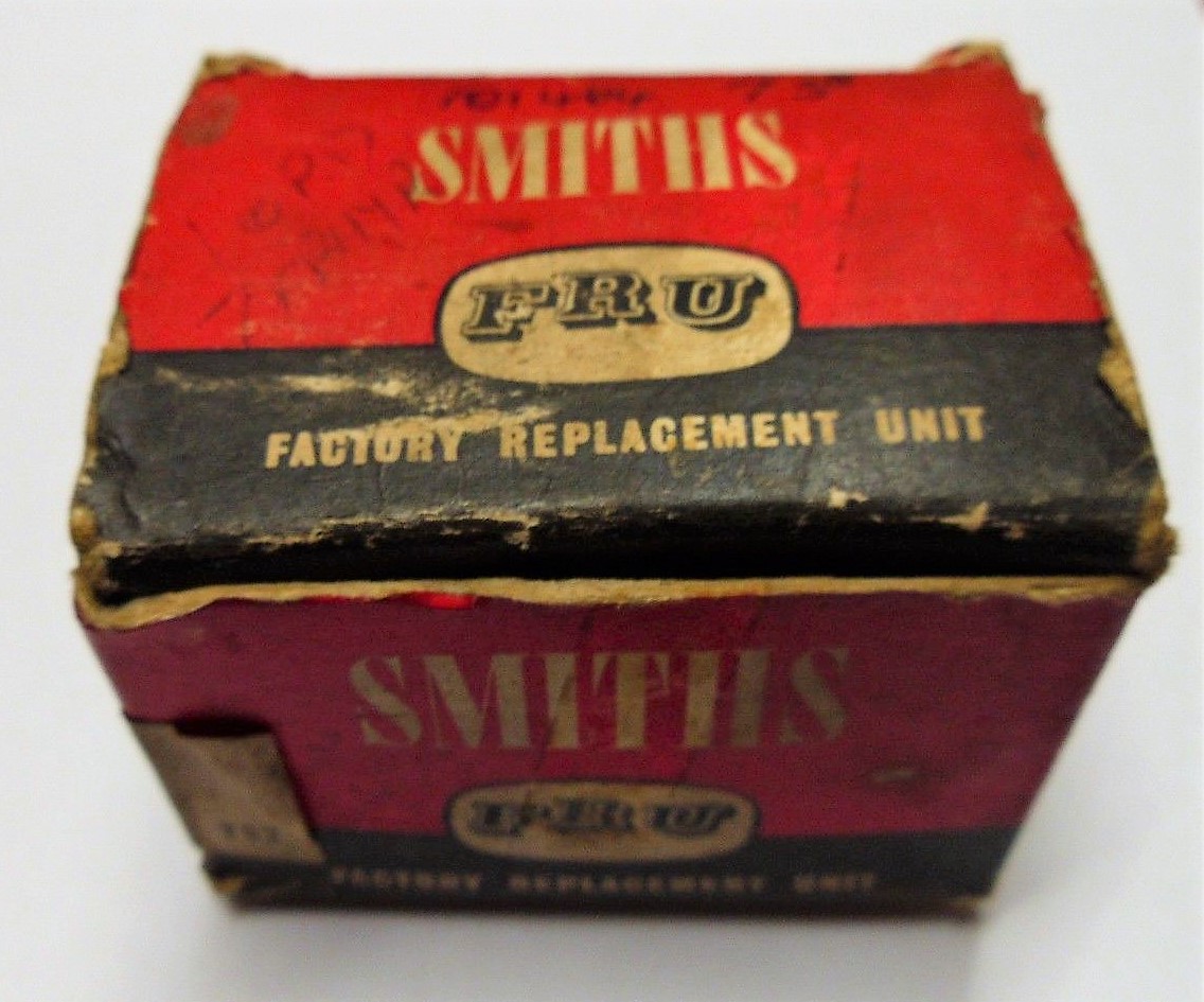
  Smiths X.43570/28 with 73°C (163° F) opening temperature as “Factory Replacement Unit” (FRU)

XK140

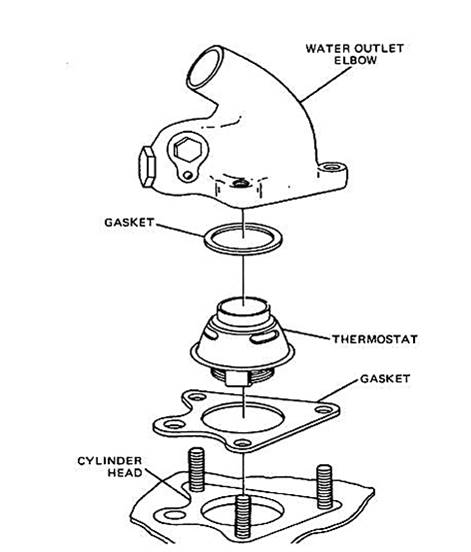
For the XK 140 engines, the thermostat was moved to the water outlet of the cylinder head. In March 1955 (engine number G2841) Jaguar announced that a new thermostat was fitted coded C.3731/1 (Smiths X.43570/5) but this version was already applied on the XK 120’s with a heater. Also reference X.43570/28 is used by Jaguar for C.3731/1; this version has an opening temperature of about 73°C (163° F). This old thermostat Smiths 43570 thermostat with an opening temperature of 60°C was no longer used. An alternative (winter) version carried Jaguar code C.7105 (Smiths X.43605/3) with an opening temperature of 83 (181° F).

XK150

The XK 150 range had yet another Smiths bellows-type thermostat with Jaguar code C.12867 having an identical opening temperature of 73° C (163° F) or C.12867/1 with an opening temperature of 80° C (176° F) for extreme winter climates. The corresponding Smiths numbers are not exactly known.  Jaguar C.12867 for the Jaguar Mk 2 versions refers to Thermostat 02-0013 (which is an unknown brand code) and has an opening temperature of 70 to 75° C.

Change of part numbers and a (slightly) larger thermostat diameter

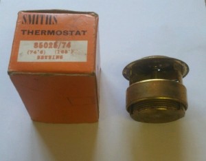
The Smiths coding system changed in early 1958 whereby the X.43xxx numbers were replaced by X.85xxx numbers, some with and others  without the X prefix. Jaguar Service Bulletin No. 235 of January 1958 informs dealers that a new thermostat version has been introduced that has an increased outer diameter. Although this increase of .010″ or 0.25 mm is rather small, Jaguar changed the “Water Outlet Pipe” (or thermostat housing) for (all?) XK engines as there was “a possibility of the movement of the thermostat being restricted by the smaller bore water outlet pipe“. Note that SB 235 contained an error (wrong Smiths number quoted for old and new version) that has been corrected in SB 239 of February 1958 (although it contained a new typing error: X.85024/74 instead of X.85025/74).

It is therefore possible that the later Smiths thermostats with part number (X.)85025/xx may touch the walls of the older water outlet pipes. However, if you thoroughly clean the old water outlet pipes with sandpaper you will remove easily .010″ or 0.25 mm. Using older thermostats (X.43570/xx) in later pipes remains always possible.

Apart from the diameter, also the overall height of the later Smiths thermostats changed. The early X.43570 thermostats measured about 2 inch (51 mm) whereas the later Smiths thermostats with code X.85025 measured about 1 13/16 inch (46 mm). The screen (blocking the by-pass) still moved to the correct position. This implies that the later Smiths thermostat used a different bellows system that would expand over a shorter distance given the same temperature rise. Note that AC manufactured bellows thermostats show a certain (constructional) resemblance with the later Smiths versions, having an overall height of about 1¾ inch (44 mm).

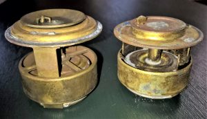
 Smiths X.45370 (left) is taller than X.85025 (right).

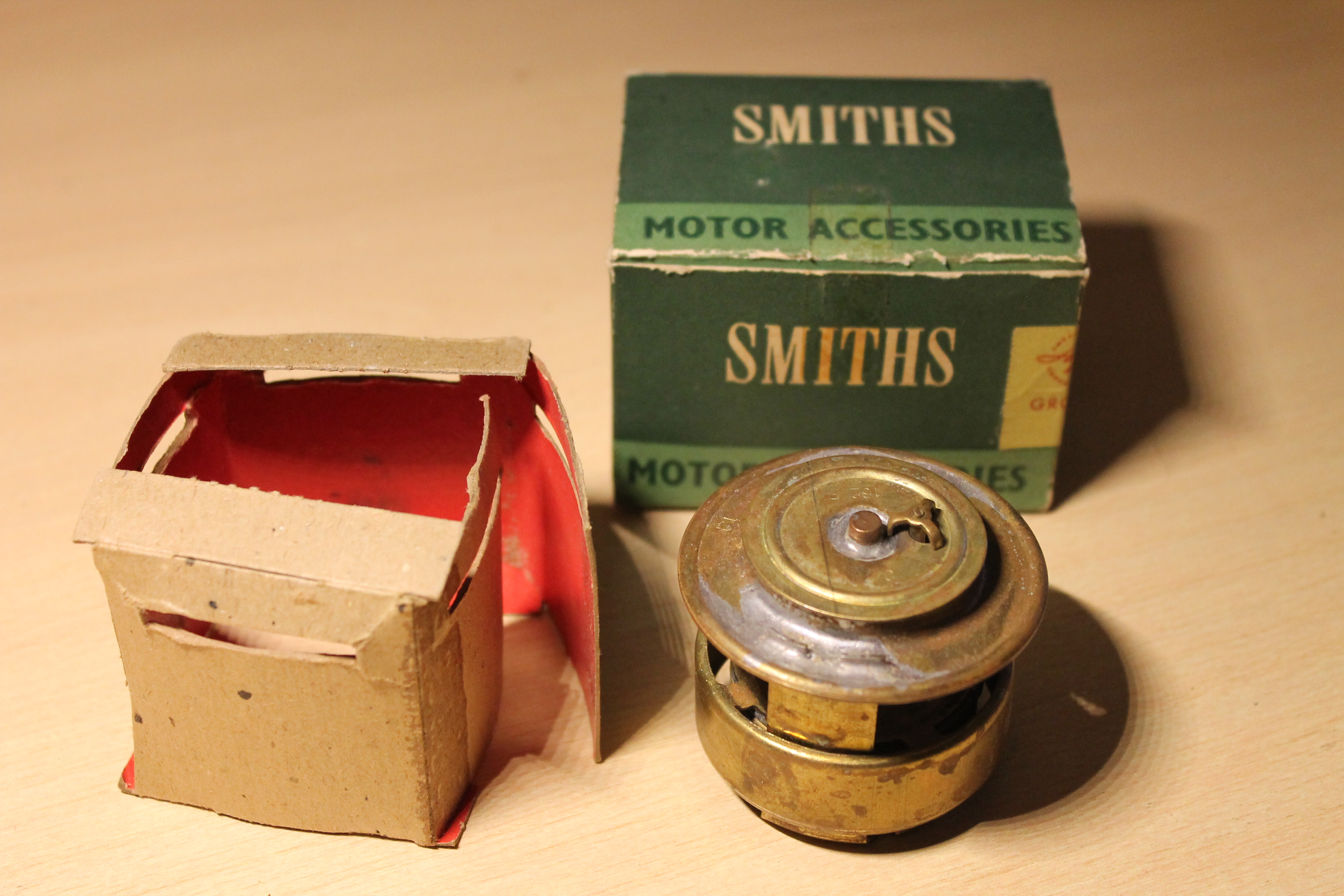
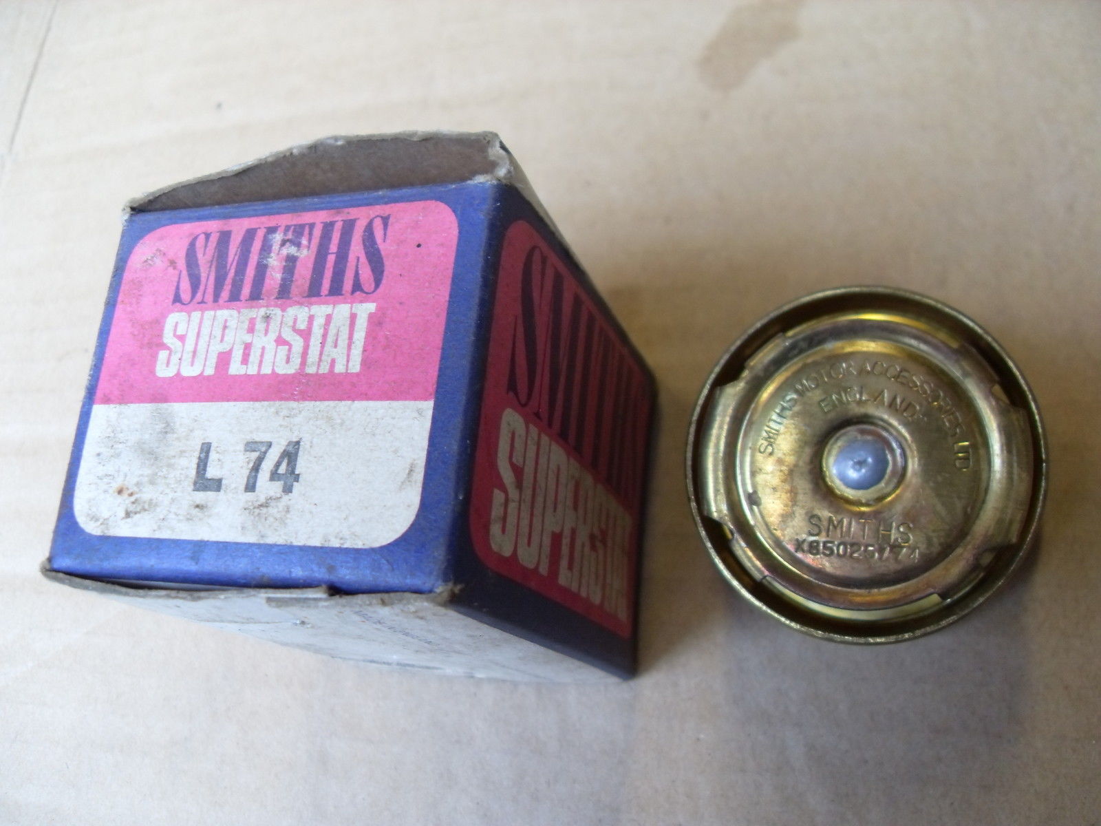
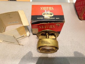
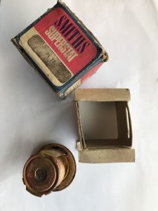
Smiths thermostats initially had green boxes with “Motor Accessories” pinted on the sides. Later Smiths made a dedicated blue & purple box for their thermostats using the name Smiths “Superstat” printed on the box: thermostats packed in these boxes still have the X prefix for the 85025 number.  Around 1960 a new orange packaging was introduced.

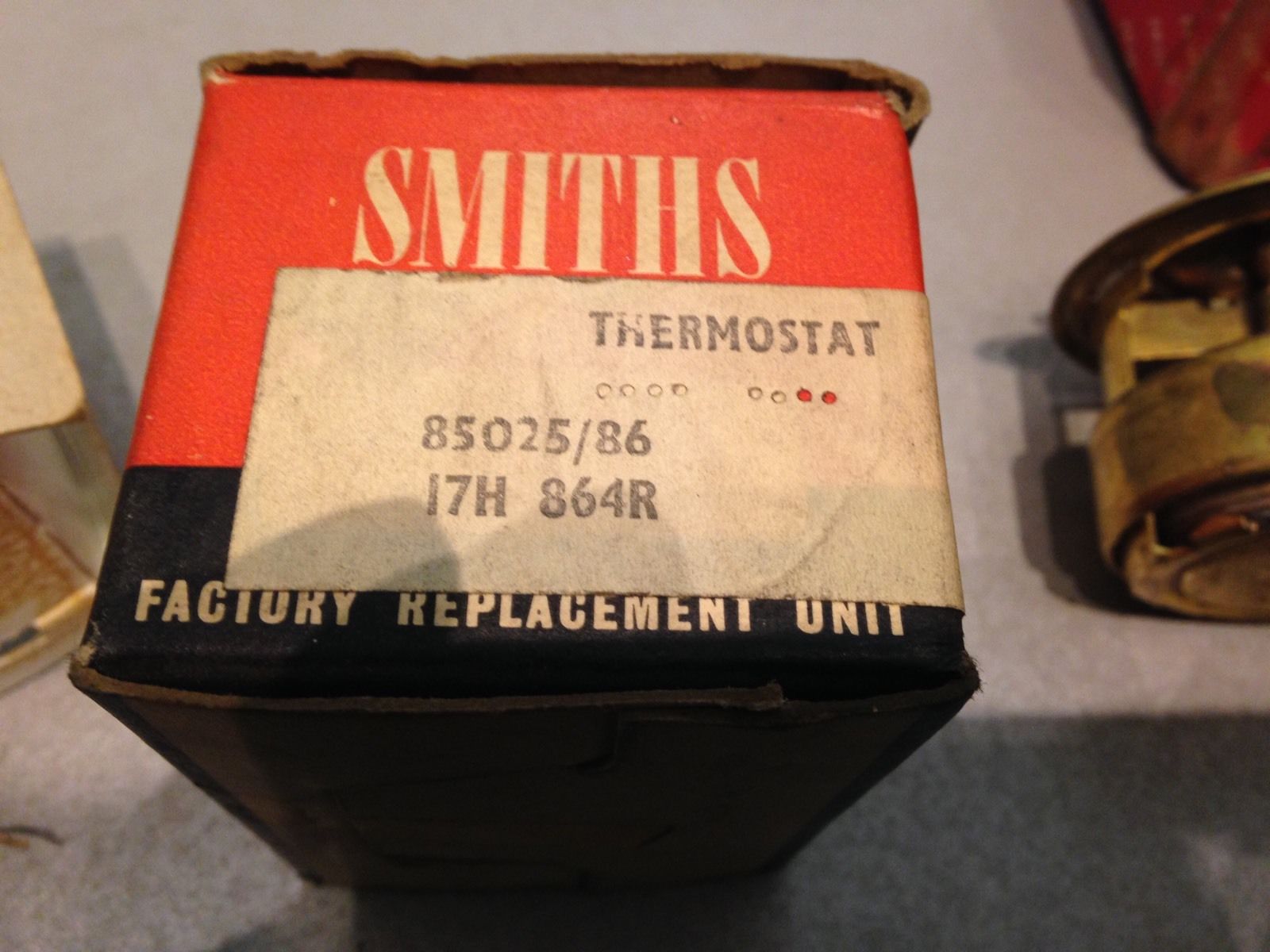
We also observed Smiths thermostats in a FRU packaging in red & black. These “Factory Replacement Units” also have sometimes the BMC code printed on the box label.

Note: the term “Superstat” is only used for a short period by Smiths. Stant (USA) still use the term “Superstat” for their thermostats.

Note: there were more Smiths thermostat-temperature versions available than the ones Jaguar had chosen. They are sometimes close to the nominal value Jaguar opted for. Examples: 85025/70 instead of 85025/74.

Survey of Smiths old and replacement part numbers:

Survey Smiths thermostats bellows 
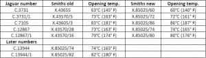
Smiths bellows type of thermostat survey.
original packing 85025 72 Smiths part X.85025/70 in original green box
Smiths X85025 74 in box Smiths X.85025/74 in “Smiths Superstat” box
Smiths Thermostat newer box Smiths part X. 85025/70 in later orange box
Smiths 85025 74 in box Smiths 85025/74 in orange box
Smiths 85025 - 86 Smiths part X.85025/86 in orange box
Smiths 85025 86 winter thermostat in red & black box Smiths 85025 86 winter thermostat in red & black box 
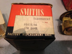
Later Smiths Factory Replacement Unit (FRU) packaging with 85025/86 winter thermostat

Other brands with replacement thermostats for XK engines

Original Smiths’ bellows type thermostats are difficult to find these days. After Smiths ceased production of this type of thermostat, the following brands became (and occasionally  still are) available:

1. AC-Sphinx and AC (DELCO)

2. Lucas (Motostock) (made by AC Delco)

3. Quinton Brivec / Quinton Hazell (made by Quinton Brivec)

4. Remax (made by Quinton Brivec)

5.GH thermostats (made by Quinton Brivec?)

Survey of AC branded bellows type thermostat with screen

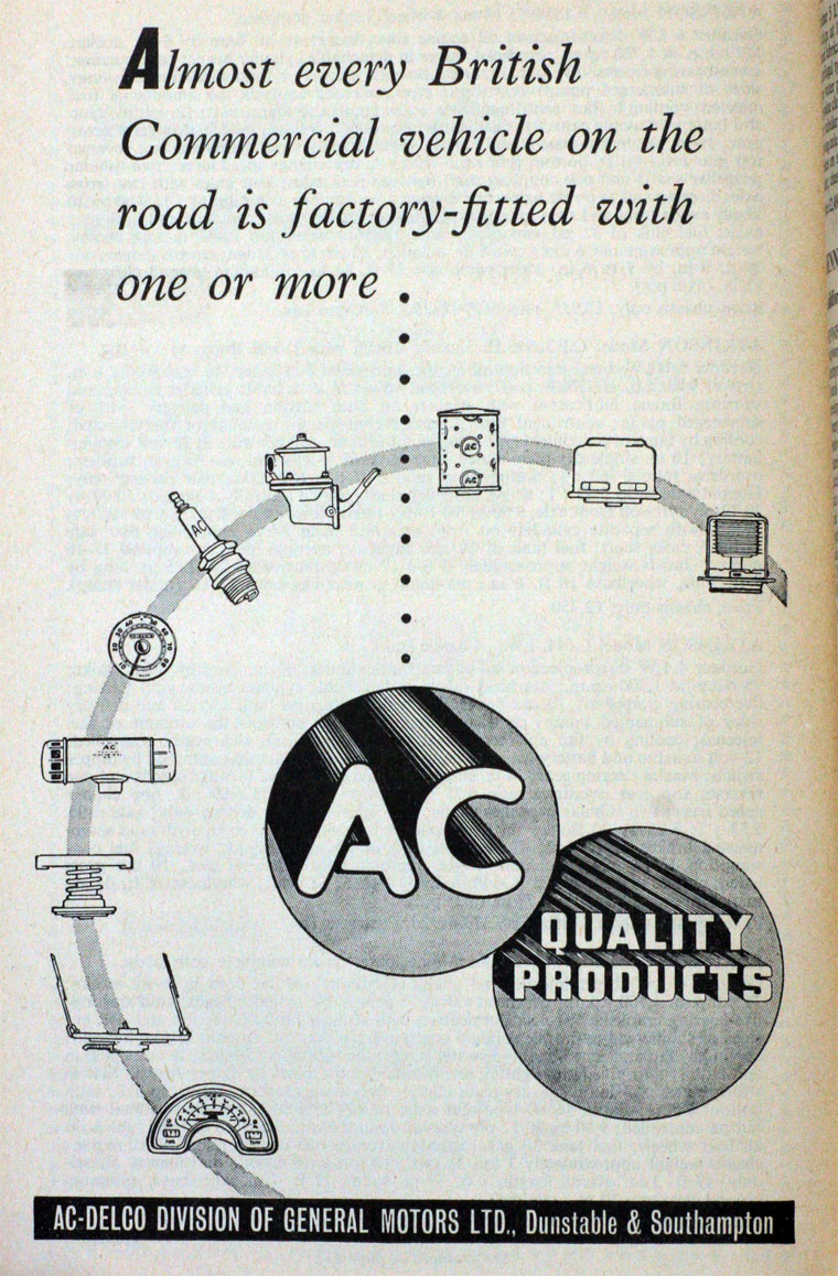
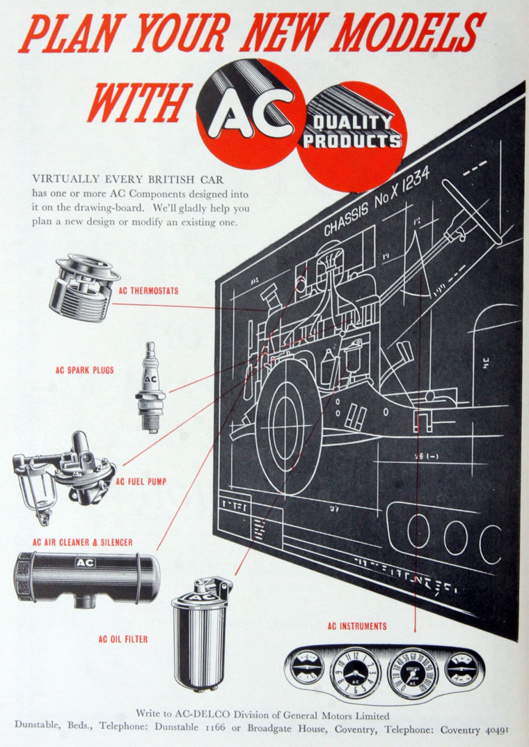
In 1952 AC Sphinx Spark Plug Co in Dunstable changed its name to AC-Delco, becoming a Division of General Motors Ltd. The Dunstable plant closed in early 2003, by then occupied by Trico Products. Also manufacturing facilities in Southampton. Main Office AC Delco at Stag Lane, Kingsbury, London NW9 OEH. The AC Delco company delivered a.o. thermostats to many UK car manufacturers beside Jaguar. See also the adds below dating from 1954 and a pre-1952 bellows thermostat still branded AC-Sphinx .

AC thermostat add 1 AC thermostat add 2 AC Sphinx thermostat

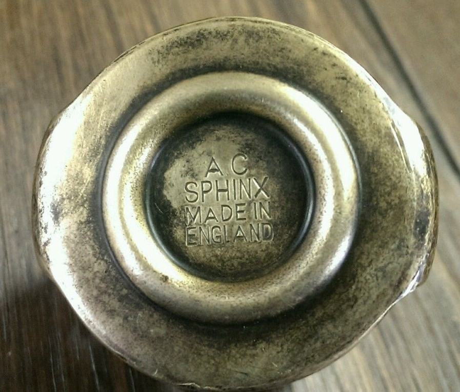
After WW2 AC Sphinx supplied two ranges of “bellow-type” thermostats:  TC series without sleeve and the TF series with sleeve or as AC called it in a 1948 advertisment:  “the by-pass type of thermostat

 AC Sphinx adverisement of Aug 1948

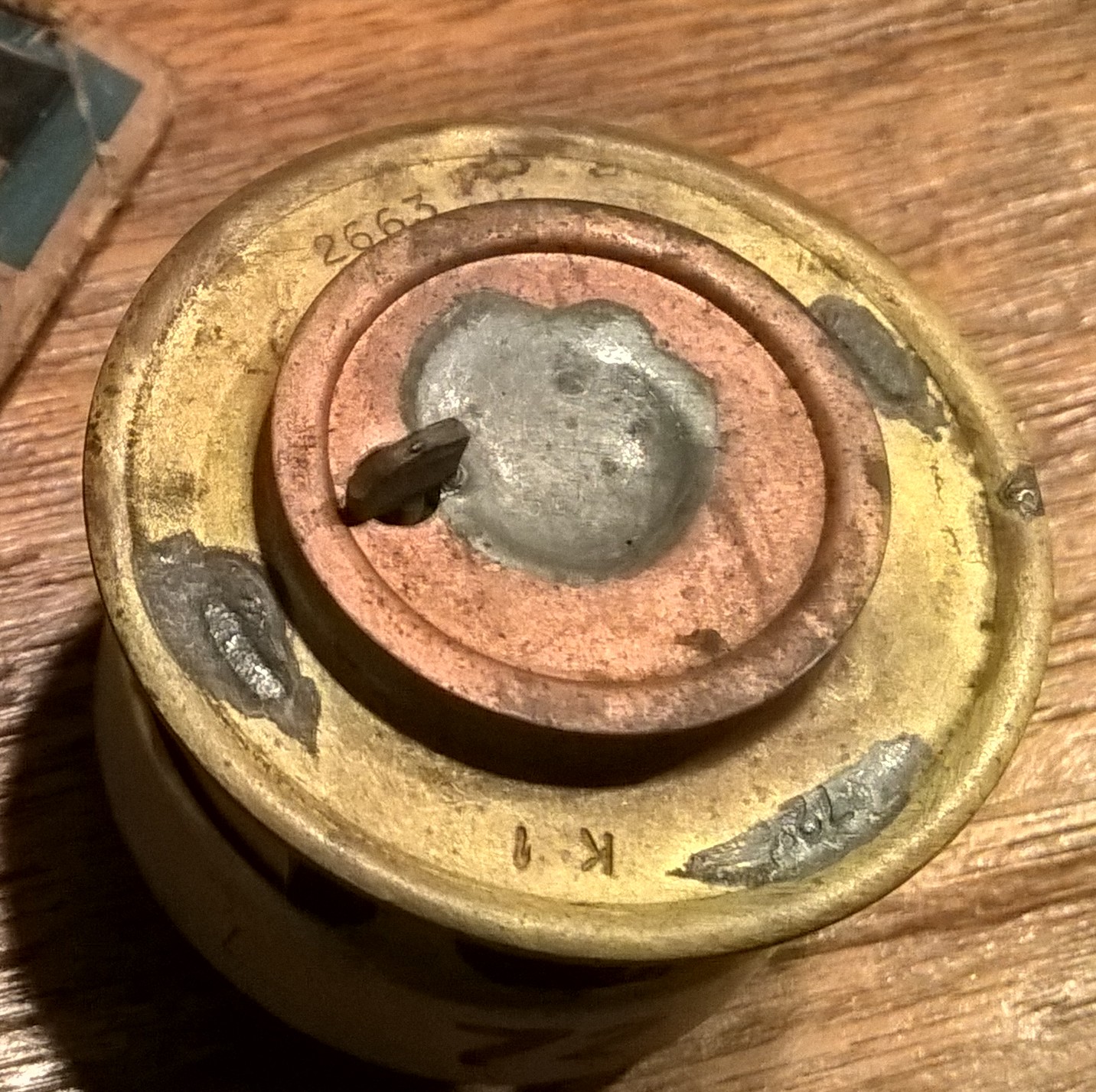
Four different TF versions were manufactured and each one had an internal manufacturing code (next to the commercail code and the temperature stamped on the top). These numbers can be used as an additional check.

  • TF-1    72° C     2235, 2663
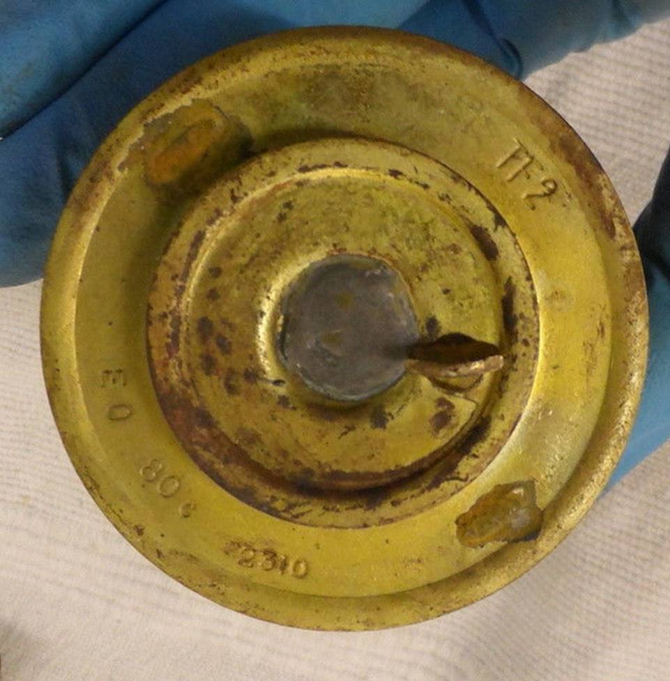
  • TF-2    80° C     2233, 2664 and later 2310
  • TF-3    68° C     2202
  • TF-4    86° C     later 2307

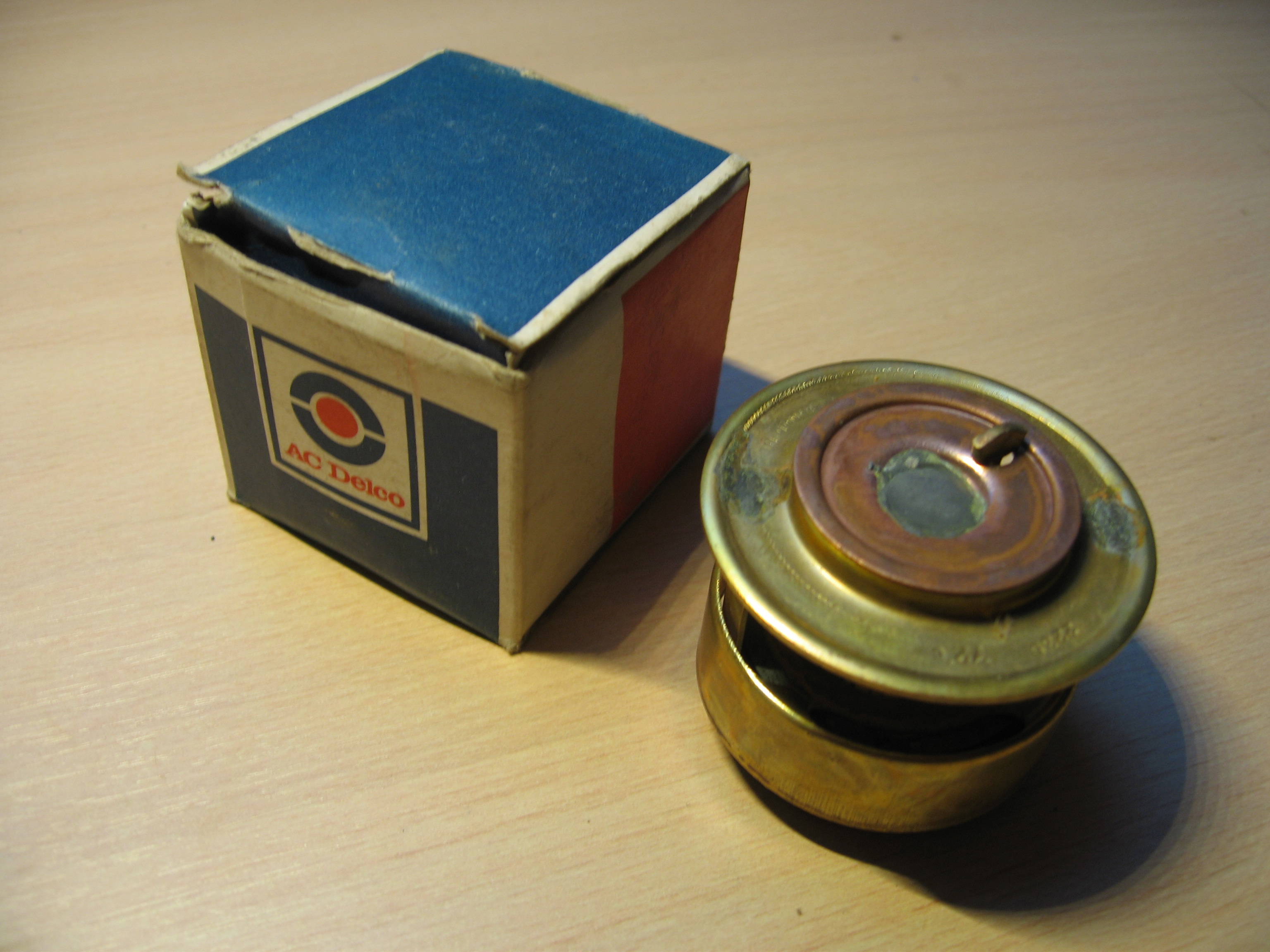
Different types of AC packaging are known: four are shown in this overview. We assume that the oldest packaging is printed in blue and yellow with the AC logo in red (see TF-4).  Then there is a packaging without the yellow accent (see TF-1 LH photo), followed by white and blue packaging still AC branded (see TF-2 RH photo). The fourth type has AC Delco printed on the box (see TF-1 RH photo).

AC (DELCO) No TF-1 thermostat (replacing Jaguar code C3731/1 which had an opening temperature of 70° C). Opening temperature: 72° C (158° F) summer thermostat.

 Thermostat AC Delco TF1 AC TF-1

AC (DELCO) TF-2 thermostat (intermediate solution between Jaguar code C3731/1 and Jaguar code C7105). Opening temperature: 80° C (176° F) winter thermostat with manufacturing code 2310. TF-2 thermostats were available in a box or packed in a blister.
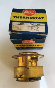
  AC TF2 thermostat TF-2

AC (DELCO) No TF-3 thermostat with opening temperature 68° C (155° F) for “hot climate” conditions

image

AC (DELCO) TF-4 thermostat (replacing Jaguar code C7105 with opening temperature at 83° C). Opening temperature: 86° C (186° F) as winter thermostat.

image AC thermostat TF4

The RH photo is interesting as it shows a TF4 stamped thermostat with a 68° C temperature which should have been 86° C !! The production code 2307 is however correct for a TF4 version. After checking it turned out to be a correct TF4 thermostat as it started to open at about 84° C. Probably this whole production batch had this error, so you have been warned…

Survey of Lucas (Motostock) (made by AC Delco)

In the 1980s the automotive activities of Smiths had been sold to Lucas and later to a group of factory employees. This probably explaines that Lucas started selling Smiths thermostats, although they were most likely made by AC Delco of Dunstable (UK).
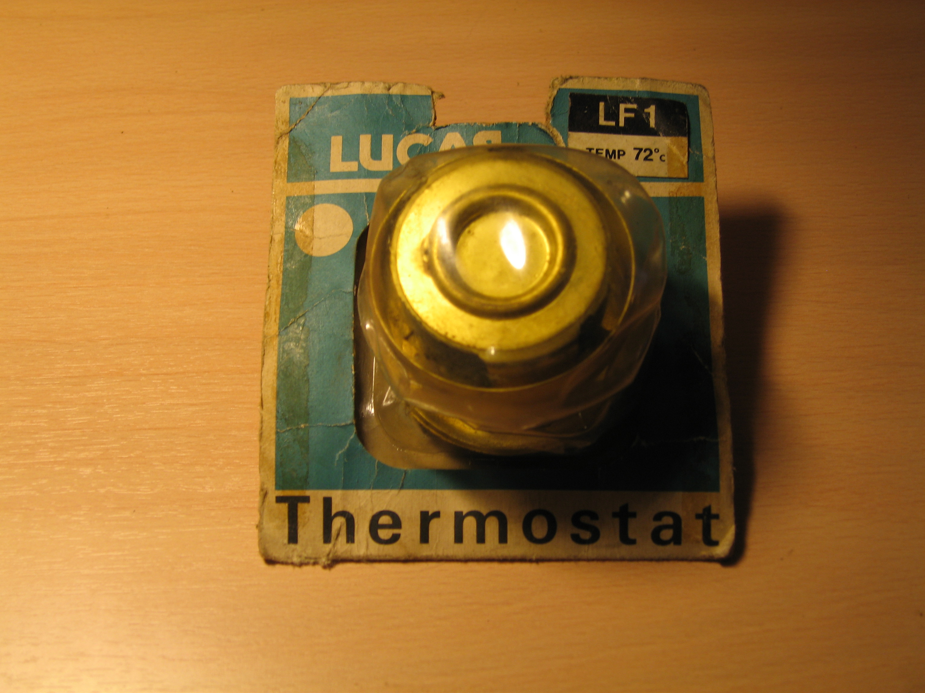
Lucas LF1

Has an opening temperature of 72° C (160 F) and has the correct screen around the bellows

Thermostat Lucas TF1 
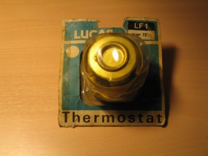
Lucas LF1 in early packaging type

Lucas LF2

This version has an opening temperature of 80° C (176 F) as winter thermostat. This version has the correct screen around the bellows.

image Lucas LF2 in later packaging type

Survey of Quinton Hazell and/or Quinton Brivec

 Thermostat Quinton Brivec WT201 
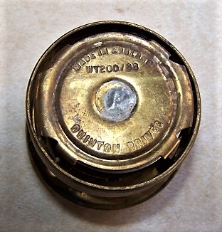
Examples of Quinton-Brivec thermostat and typical box design with Welsh Dragon

Initially marketed under the  Quinton Brivec brand ( located in Colwyn Bay, Wales and a divison of Quinton Hazell); see photos above. These thermostats had a special  Quinton Brivec packaging showing the Welsh Dragon. Later the company brought the packaging under the Quinton Hazell brand (with a smaller Dragon). The code numbers are (more or less) identical for early and later packaging versions.

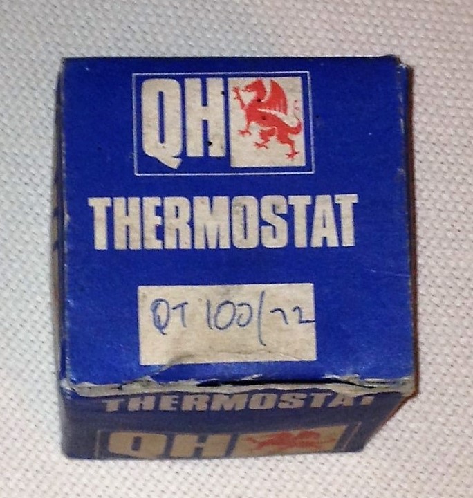
Quinton Hazell QT 100/200 series

Type QT 100/70, QT 100/72 and QT 100/74

These are bellows-type thermostats  (including sleeve) with an opening temperature of 70°, 72° and 74° C respectively.

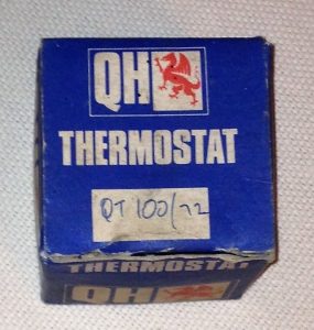
 QT 100/72 in original Quinton Hazell box

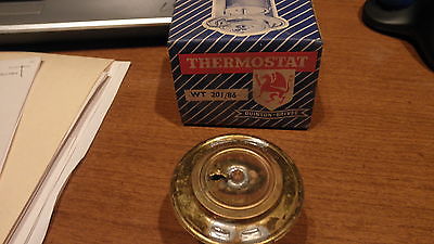
Type QT 200/80 and QT 200/86

Opening temperature: 80 C (176 F) and  86 C (187 F) winter thermostat. With the correct sleeve.

imageType QT 200/80 or WT 200/80 (for “winter” thermostat?)

Survey of Remax thermostats

Remax of London had been established in 1928, manufacturing and supplying mechanical (precision) replacement parts for automobiles. After WW2 the company added Automobile Electrical Companents to their portfolio. Thermostats must have been a later addition to the sales programme, probably from the late 1960s onwards.

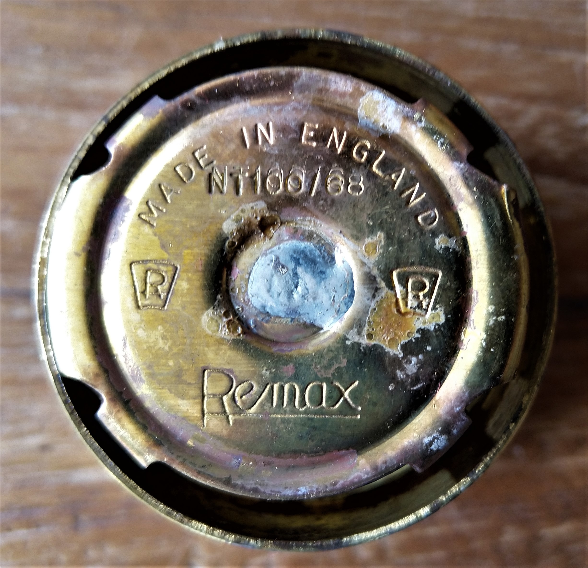
There is a strong resemblance between the Quinton Hazell and the Remax thermostats, which may lead to the conclusion that QH (or better Quinton Brivec) was their thermostat supplier. Even the type coding was almost identical: where QH refers to QT100 thermostats, Remax opted for NT100.

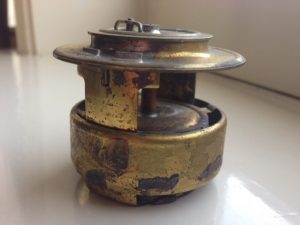
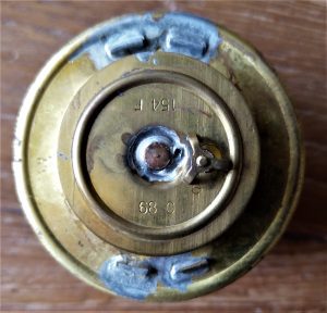
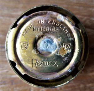
                                                                                               Remax NT100/68 thermostat has an opening temperature of 68 C.

GH thermostats (most likely made by Quinton Brivec)

Another UK brand named GH has been reported with bellows thermostats that have a large ressemblance with the afore mentioned thernostats as made by Quinton Brivec. There is very little information about the GH company.

The photos below show their type A70 with a 156 F or 70 C opening temperature. Also note their dedicated packaging branded GH.

This image has an empty alt attribute; its file name is GH-Thermostat-box-1024x897.jpeg  This image has an empty alt attribute; its file name is GH-Thermostat-top-70C-1024x1021.jpeg         
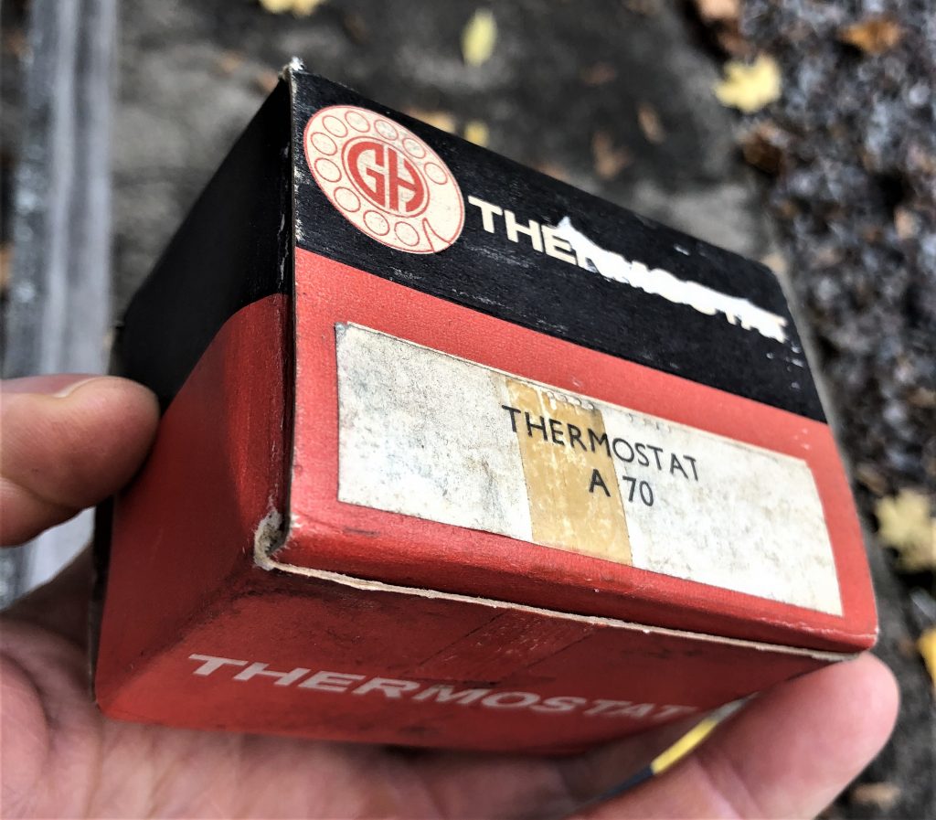
GH thermostat box                                                     Top side is tamped 156 F and 70 C
This image has an empty alt attribute; its file name is GH-Thermostat-bottom-70C-1024x966.jpeg 
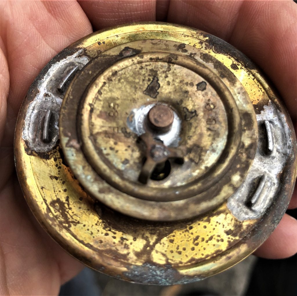
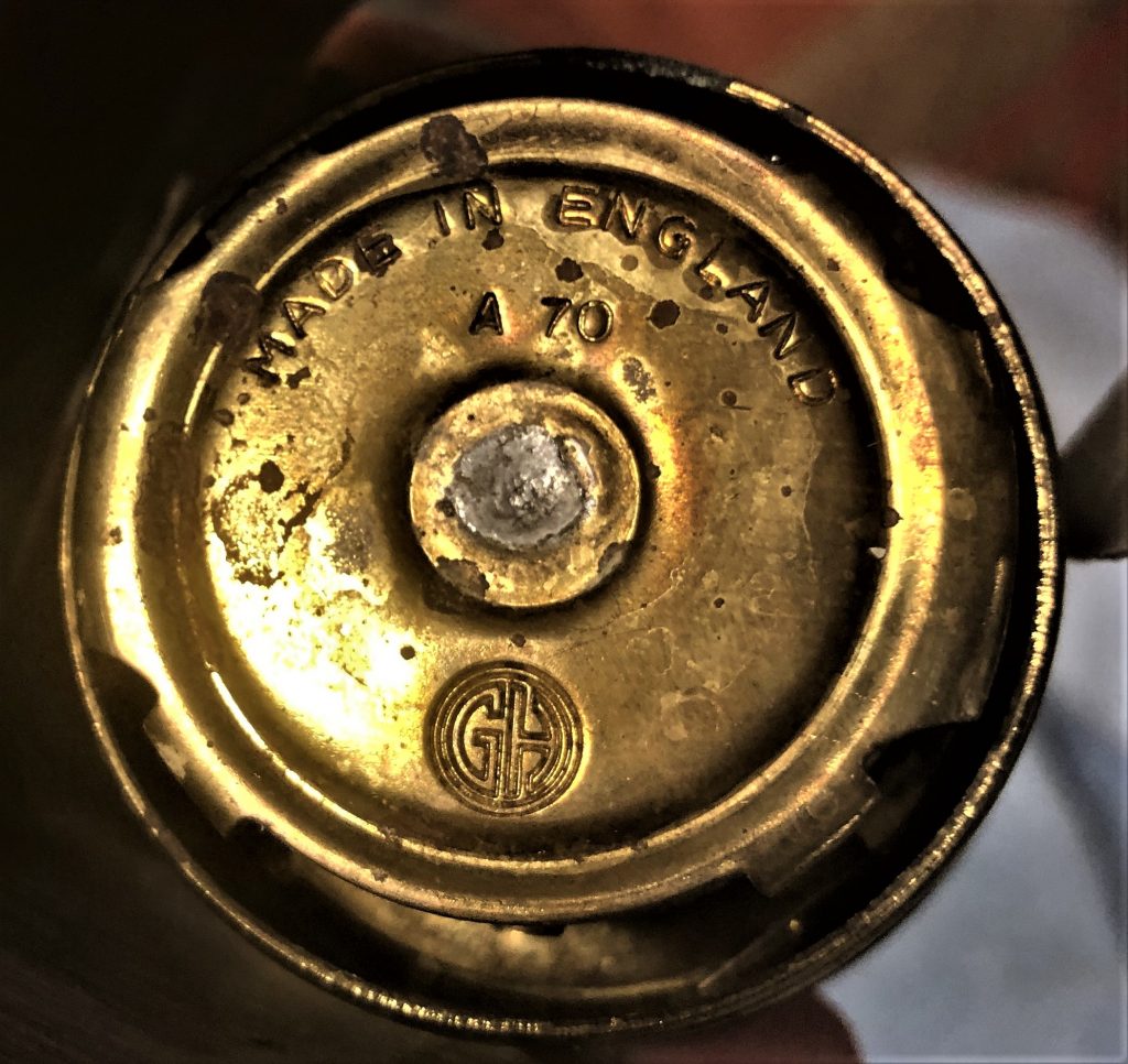
Bottom side is identical to other Quinton Brivec types but stamped GH

Mounting position of thermostats

All thermostats described in this article have a small hole in the valve. The thermostat should be positioned such that the small hole is always on top, to allow air (bubbles) to escape from behind the thermostat  during the refilling process.

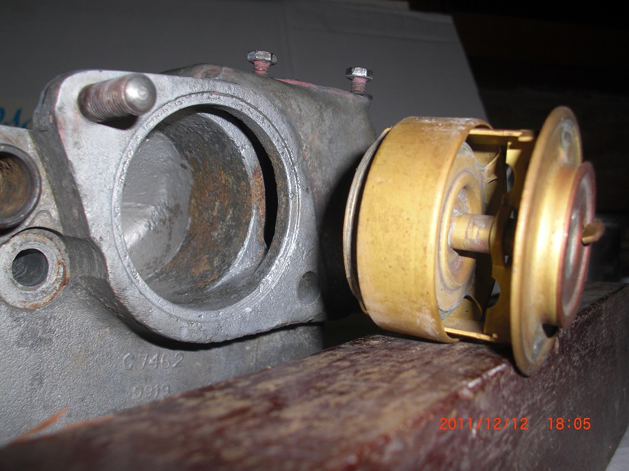
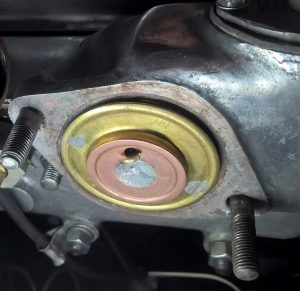
 Small hole correctly positioned at top (XK 140)

Non screen bellows-type thermostats

Although a “bellows-type” thermostat, this version has no screen around the bellows to block the water opening like the original version and is not recommended for the earlier XK engines. They have been supplied by Smiths, AC and Quinton Hazell. In reverse it is, however, possible to use the earlier “bellows” type with screen (e.g. C3731/1) on the later engines.

Smiths 85032/70 and /80, 85035/78

Available with opening temperature of 70° C (158 F), 78° C or 80° C (176 F) and others.

 Smiths (non-screen) 85035/78 in 2nd generation “Superstat” box
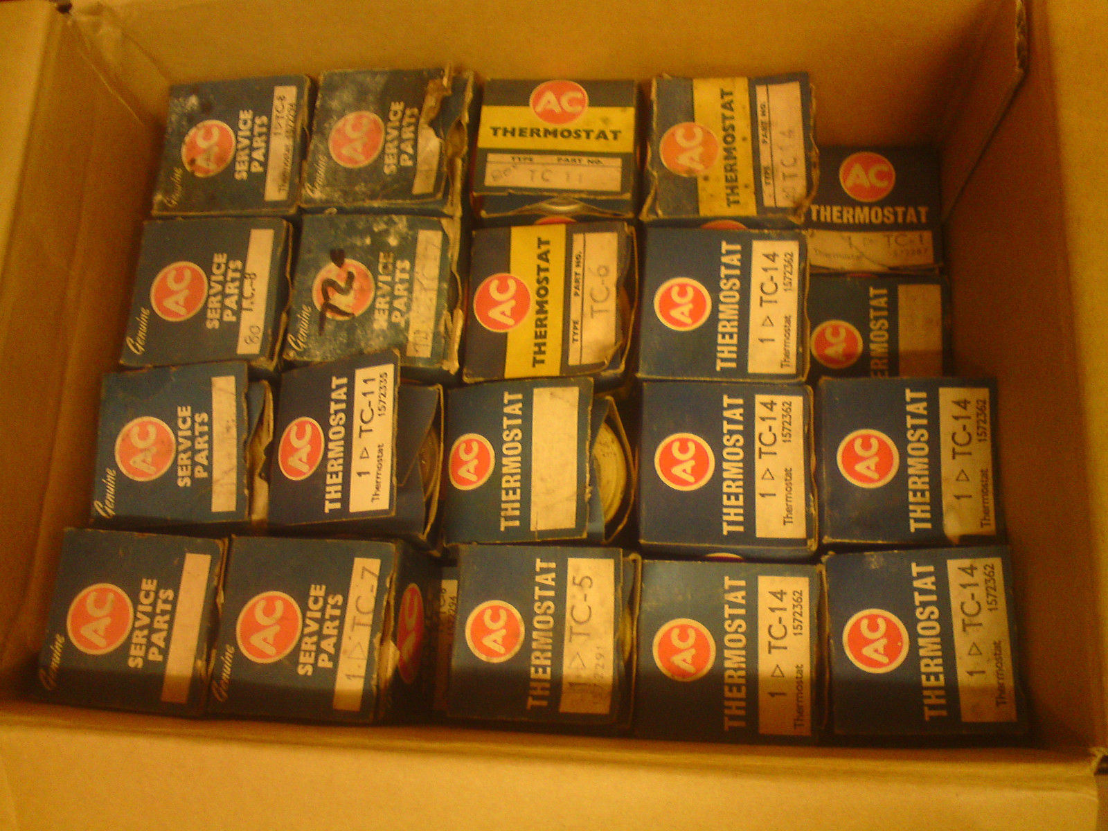
AC (DELCO) TC range of thermostats

AC-DELCO had a large range of bellows thermostats without a screen. The programme comprises the following types:

  • TC1 – 80c
  • TC2 – 72c
  • TC3 – 80c
  • TC4 – 77c
  • TC5 – 86c
  • TC6 – 72c
  • TC7 – 72c
  • TC8 – 80c
  • TC11 – 80c
  • TC12
  • TC14 – 80c
AC thermstat type TC non sleeve AC TC thermostat survey  
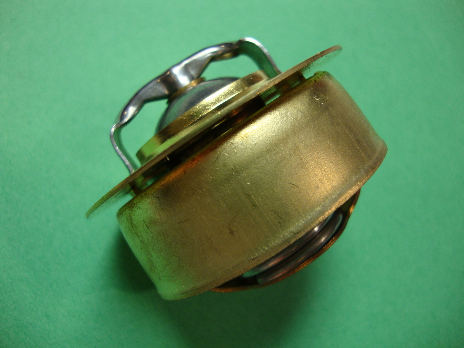
AC thermostat of the “non-screen” TC  type                 Still available but incorrect

Quinton Hazell QT 101 and 201 series

Available as QT 101/70 and QT 101/80 with opening temperature of 70° C (158 F) or 80° C (176 F). Also QT 201/86 is available as a “winter thermostat”.

image image image

QT 101/72                                            QT 101/80                                           QT 201/86

New aftermarket thermostat with sleeve: correct type!

Recently some suppliers introduced a correct type of bellows thermostat with sleeve. This version is apparently intended for the MGA, but looks to fit Jaguar XK’s as well. This is an almost exact copy of the original thermostats and functions correctly.

Reporduction thermostats China Perfect copies. (Photo courtesy Bob Richards)

New aftermarket thermostat with sleeve: incorrect type!

Aftermarket thermostat  image_thumb.png

The sleeve of this aftermarket thermostat (above LH) is positioned just below the upper fixation of the thermostat whereas with the original version (above RH) the sleeve is positioned at roughly 25 mm (1 inch) lower.

This type of thermostat (without the extra ring soldered to it) had been invented and produced by the Robertshaw company until about 1999. The extra brass ring has been added to the thermostat by a distributer who modifies the thermostat for use in ‘British’ applications.

Thermostat and by-pass

At the above photo (courtesy Robert B.) we see that the by-pass opening just below the surface is open when the thermostat is closed. This implies that the coolant remains within the engine to shorten warming-up time. When the thermostat commences to open the screen moves upwards (to the right on the above  photo) and gradually shuts the by-pass. Coolant now flows from the engine to the radiator only. In case of the aftermarket type used in a Jaguar XK engine, the by-pass is blocked by the screen meaning it will take much longer before the engine gets warm.

In addition, early XK engines have a “mixture enrichement device” for cold starts. The time during which extra fuel is supplied to the engine is controled by an “Otter switch” that will stop the enrichement the moment the cooling fluid reaches a temperature of about 35C  at the position of the Otter switch. It is evident that when the by-pass is not closed, it will take much longer before the mixture enrichement period will be ended. A too rich mixture lead to inregular running of the engine (and does certainly not contribute to a better environment!).

All other bellows or wax-type thermostats without a proper screen will warm-up quicker than the above “after market type”, but the by-pass will remain open at all times meaning a part of the coolant-flow remains within the engine and will not pass through the radiator. The use of these types of thermostat normally results in a higher coolant temperature!

XK’s cooling system conversions

Early XK engines had a cooling system pressure of about 4 lbs./sq.in. Newly developed engines in the 60’s had an increased cooling system pressurization (of at least 7 lbs./sq.in.) and the higher system pressure negatively affected the functioning of the bellows type design as it relied on expanding gases within the bellows.

So in case you have modified your cooling system (and increased the pressure), it is advised to replace the bellows-type thermostat for a wax-type thermostat. Fitting a separate blanking sleeve (that blocks the by-pass) would be an option to compensate for the absence of the sleeve. This may overcome the coolant temperature-rise that normally results from using a “non-sleeved” bellows thermostat.

image                         Blanking sleeve for “non-sleeved” thermostats has same diameter as thermostat

Felt for Fuel tank XK 140

Felt used for fuel tank XK 140

Felt is used between the fuel tank and the chassis & body, but the actual amount, size and position of the various pieces of felt remain unclear from the information in the Service Parts List. Listed are the following items for the XK 140:

clip_image002

The (black) felt used by Jaguar is about ⅛” (or 3 mm) thick and normally 2”(or 50 mm) wide (except C8414 which is 1”or 25 mm wide). The positions of the above pieces of felt:

  • Basically the XK 140 fuel tank has 3 felt strips (18” or 45 cm long) placed across the top of the tank front to rear, but the filler opening at the LH side “interferes” with one of these three strips (see 3rd bullet).
  • At the LH and RH end of the tank the felt runs from the tank mounting points front to rear over the tank. The RH strip is coded C8373. For the LH strip see 3rd bullet.
  • Because the fuel filler opening is placed at the LH side of the tank, the felt strip at this side is not 18” long but had to be cut in two pieces: C8371 and C 8372 with a total length of 16” leaving 2” space for the filler opening.
  • The third strip (again C8373) is placed in the centre of the tank parallel to the other strips.

The (original situation) picture below shows where the LH strips went. Black glue was used to hold the strips on to the tank.

clip_image002 Original  clip_image002[4] Restored
clip_image002[6] The top strips installed on the fuel tank.

There is another 44” (or 110 cm) long and only 1”(or 25 mm) wide felt strip placed along the top of the tank from side to side. This strip is positioned along the front of the top of the tank to protect the tank from rubbing on the chassis cross-member.

clip_image002[8] Tank in final position including felt strips

Improved Fuel Pump pipe connections

Improved Fuel Pump pipe connections

Two copper fuel pipes are connected to the fuel pump during the assembly process of the XK 140. It concerns C7556 (Fuel pipe (centre) from rear pipe to inlet connection on fuel pump) providing fuel from the tank, and C7557 (Fuel pipe (front) from outlet connection on fuel pump to flexible hose) pumping fuel to the carbs. Apart from the fact that both pipes have a (very) sharp bend where the connection with the fuel pump is made (asking for maximum care when installing these pipes), these pipes sometimes touch the Fuel Pump Shield C8010 with the risk of damaging the fuel pipes over life.

In case the fuel pump has to be removed for inspection or repair, these copper pipes are very difficult to remove as they are partly behind the main chassis rails and there is very little space to manoeuvre these pipes away from the pump.

image Fuel pipe connections on the XK 140 and (early) XK 150

The pipe connection system was improved many years later by Jaguar on the new 150 “S” versions, introducing a new flexible hose connection C14721 (Flexible petrol pipe from outlet side of rear petrol pump to branch on front pipe) with a banjo at one end and a compression (“olive”) connection for ⅜”copper pipe at the other end. This hose is connected to the pump using a Banjo Bolt C11488 instead of the male brass unions on the copper pipe (SU part Nº AUA 4650) as used for the XK 140.

imageFuel pipe connections on the XK 150 “S”

We can greatly improve the pipe-to-pump connections on the XK 140 and (non-“S”) XK 150 by using two of these flexible hoses (C14721) and Banjo bolts (C11488) and connecting them to the (shortened and now straight) copper pipes C7556 and C7557 using a ⅜” pipe male union that fits the female union at the end of the flexible hoses.

image

The result is a very “flexible” solution offering easy assembly during the restoration of your car as well as disassembly for maintenance purposes. And last but not least: it looks very professional!

image

Lucas C45PVS “Special Equipment”

Lucas C45 generator overview as applied for Jaguar XK120, 140 and 150

1. Generators (dynamos) in the pre-XK era

Very early SS Jaguars had Lucas C45YV/1 dynamos, until about 1937 SS Jaguar started using Lucas C45PV-3 generators for the 2½ and later 3½ Litre versions. These dynamos were also available as “Special Equipment” version (in addition to the more common “Standard” version). This is why many illustrations and photos from about 1934 onwards, show Jaguar engines with the typical “Special Equipment” generators having a nickel-plated yoke, black strap over the inspection holes for the brushes and (of course) the “Special Equipment” badge.

These first pre-war C45PV/3 dynamos for the larger engines had type number L1/1 and Lucas part number 238.186. Note that pre-war Lucas part numbers consisted of 6 digits.

The Jaguar “Spare Parts Catalogue” of December 1947 states that Jaguar (SS) 100 and other 3½ Litre models from 1938 onwards used the Lucas C45PV-3 generator (with Jaguar part no. C1075) having a cast iron pulley with integral fan (Jaguar part no. C1076); the latter was continued over many Jaguar models until 1954. We may therefore assume that also Mk IV and Mk V models have used this type of generator (to be confirmed).

2. The Special Equipment version of the C45 generator series.

From 1948 onwards Jaguar choose the “Special Equipment” version of the C45PV-4 model range with model number C45PVS, followed by C45PVS-5 and C45PVS-6, for the XK 120, 140 and 150. This generator is part of the C45 range, but there are (major) differences within the total range and parts are not always interchangeable.

Lucas generator 22429 Example early nickel-plated yoke with black strap.

The Lucas coding for the C45PVS generator model is composed as follows: generator with Concentrically mounted armature with 4.5” diameter yoke; Voltage control, 2-Pole system with long type yoke; Ventilated; optional Special finish, followed by an indication of design update (-4 or -5 or -6).

It is unclear whether the “Special Equipment” version of the C45PV-3 generator was ever coded PVS-3. There are reasons to believe that the “S” was only added when the C45PV-4 dynamo was introduced in 1948. Lucas emphasizes the higher position of the “Special Equipment” version by stating in their brochures that these “have generally been applied to High Speed Sports and other special cars”. They further supported the use of “Special Equipment” versions by giving it a unique, generic type number C45PVS (instead of C45PVS-4). Only with the introduction of its improved successor in 1953 they felt the need to introduce the type number suffix: C45PVS-5.

From 1945 onwards four main groups of C45 generators can be distinguished whereby the first 2 groups have been mentioned here for reference only:

1. C45P-4 and P-5 series: this is a fully closed, non-ventilated version with a cutting-in speed of 900 to 1050 rpm and a maximum output of 13 Amps at 1350 rpm. Mostly applied for agricultural use and used in combination with Control Boxes RF97 or RB107.

2. C45PV-4 series: this is an open, ventilated version with a maximum output of 20 Amps at 1650 rpm. Applied for automotive use where a load is not exceeding 17 Amps and to be used in combination with Control Boxes RF95 or RB106.

3. C45PV-5 and PVS-5 series: is basically similar to the C45PV-4 but with the ventilation considerably improved by increasing the size and shapes of the apertures in the commutator and driving end-brackets for all suffix 5 versions. “S” versions have ball-bearings at both shaft ends. These generators have a maximum output of 20 Amps at 1650 rpm . Applied for automotive use where the continuous load does not exceed 17 Amps and to be used in combination with Control Boxes RF95, RB106 or RB310.

4. C45PVS-6 series: an improved version of model C45PVS-5) with a.o. a new armature, commutator end-bracket and brushes. Output was now 25 Amps; to be used in combination with Control Boxes RB310 (updated version 37297A with higher Amps setting).

3. Survey and timeline of C45 “Special Equipment” generator versions per XK type

Survey C45PVS generator versions.jpg

4. Lucas C45PVS models

This generation of Lucas generators has probably been introduced in 1947. Although the Lucas part number was 22429A from the beginning, the commercial Lucas type number was C45 ZV or C45 ZVH. This was a Special Equipment model, but with a different commutator end-bracket, here shown with a square housing for the roller bearing. Also note the different electrical connection with two plug type connectors instead of the later terminals. The examples shown below have date code 1 48 and 9 48 respectively. The type model changed to C45 PVS when a modified commutator end bracket was introduced (probably 1949) with part number 22429D.

  Lucas C45 2 VH 22549A 1948 Lucas 22429A had a separate square bearing housing and was never used on XK120

4.1. Lucas 22429D & E (Jaguar C2527/1)

Early XK 120s up to W5275 (1952) used Lucas generator model C45PVS, part number 22429D and 22429E. The same version was applied on early Mk 7’s up to engine # A8126. The C45PVS is a specially finished product with ball-bearings at both ends, a machined (non-passivated) nickel-plated yoke , a black painted band or strap for access to the brushes,  commutator end-bracket in natural aluminium and drive end-bracket in cast iron painted black.

The “Special Equipment” tag is made of steel and nickel-plated with black-enamel depressed fields. It is secured by two bright steel solid rivets with hemi-sphere head; later 22429F and H versions had gloss-black rivets.

Lucas C45 PVS type plate Later 22429F plate

This generator initially consisted of an armature part number 238806 with (metrical!) ball bearings at both ends. In the aluminium commutator end (C.E.) bracket (Lucas part 238845) a rubber sealed Hoffmann type 115 ball bearing was placed (dimensions Ø15 xØ35 x 11 and Lucas part 189307). This ball bearing is generally known as 6202. At the driving end a cast iron bracket (Lucas part 238796) is used with a rubber sealed Hoffmann type 117 ball bearing (dimensions Ø17 xØ40 x 12 and Lucas part 189308; also known as 6203).

image Lucas C45 PVS pulley
Early C45PVS integrated pulley and fan as one casting (C1076).

Note: Lucas 22429 generators (from D to H) used a cast iron pulley with integral fan (Jaguar part no. C1076). (Note: reproduction versions are made nowadays in cast aluminium). The later 22462B generators had a different pulley (Jaguar part number C2579), while the successor types Lucas part 22462D and E had a separate aluminium pulley and fabricated steel fan (Jaguar part number C7427 and C7428 respectively).

Lucas 22462B Comm end Dynamo CEEarly C.E. bracket without Lucas script                       Example of C.E. bracket for 22462/D with Lucas script

Note: Early C.E. brackets (both part number 238845 and 239265) apparently have been casted without any Lucas script. Later brackets from generator part number 22462/D onwards have the word “Lucas” and “Made in England” on the outside. The inside casting numbers (L134), however, are identical for both versions.

Note: The commutator end-bracket  for all “S” versions can be easily distinguished by having a larger recess for the ball bearing with an outer diameter of 35 mm; “non S” versions have a (smaller) bronze bush bearing with an outer diameter of 19,2 mm (Lucas part 238567 or 293263).

image Different C.E. bracket for Special Equipment version (top)

4.2. Lucas 22429F & H (Jaguar C2527/1)

XK 120s manufactured in 1951 and till mid 1952 used Lucas dynamo model C45PVS with part number 22429F and H. The same version was applied on Mk 7s of that period. Some modifications were made compared to the earlier part 22429E.

Lucas 22429F C45 PVS Lucas 22429F CE Note: generator C45 PVS was not painted black             Commutator End of Lucas 22429F

A new armature (239190) with ball bearings at both ends was introduced; this armature remained the same for the entire later production, including part number 22462 versions and changed only with the introduction of the C45PVS-6 model in May 1959.

Type plate Lucas 22429F Lucas 22429F pulley Type plate Lucas 22429F (December 1950)                                Pulley and fan combined in one casting

A new aluminium commutator end-bracket (Lucas part 239265) was introduced with a different bearing type: a fully enclosed Hoffmann type 115P bearing was now used (dimensions Ø15 xØ35 x 11 and Lucas part number 189237). At the driving end nothing changed with bracket part 238796 and bearing part 189308. All other parts remained the same.

The photo below shows the same 22429 generator however with a K suffix as produced in 1957. This may have been a later service-part production run for the aforementioned types.

 Lucas 22429K with built date 10 57

5. Lucas C45PVS-5 models

5.1. Lucas 22462A & B (Jaguar C5433)

In June 1952 an improved generator type was introduced for the XK 120 from engine number W5276 onwards. This version was initially coded Lucas 22462A and later with suffix B (Jaguar part number C5433). This is the new C45PVS-5 model which is largely identical to the preceding model apart from a new driving end-bracket (now part number 239012) which allows for better cooling of the generator. The bearing for this end-bracket, however, remained unchanged (Lucas part 189308). Apparently these “Special Equipment” versions were no longer nickel-plated and the yoke was (at least in case of the 22462B: see photo below) painted grey, as was the strap giving access to the brushes. At some moment (introduction of the 22462D version?) the yoke was painted in a  black colour and remained black for all following versions of the C45PVS/5 model.

Some sources indicate that the 22462B was also applied on the early XK140. The Lucas “Advanced Information” data sheet for 1955 Jaguar Cars (dated February 1955) still mentions the 22462B as correct for the XK 140 (in fact for all 1955 Jaguar models). There is however no evidence that these (grey painted) generators have ever been used on XK 140s.

image image

“Special Equipment” badge on 22462B generator painted grey (Lucas “poly-chromatic” grey?)

5.2. Lucas 22462D & E (Jaguar C5433)

With the introduction of the XK140 in 1954, the C45PVS-5 model was continued under part number 22462D, then later with suffix E. The differences between early 22462B and later versions with suffix D and E appear to relate to modifications in the two long fixing bolts which changed from part number 238521 to 272752 (see photo below right). The Jaguar code C5433 did not change although this modified generator was now painted black (both yoke and cover band) instead of grey.

image image

Note: some sources mention that the E suffix generators don’t have a strap. This statement seems to be incorrect as there exist too many 22462E generators with that strap and the opening beneath (see photo below).

image image

Lucas 22462E with opening for brushes

Part number 22462E was also applied for the XK 150 until May 1959 (up to engine V 1598) when a new generator model C45PVS-6 with part number 22496 B was introduced.

Lucas generator 22462E 1958

Note: although the specification of the generator remained unchanged, the oval brass “Special Equipment” badge was never used on the generators of the XK 140 nor XK 150.

6. Lucas C45PVS-6 models

6.1. Lucas 22496B to D (Jaguar C15255)

The model C45PVS-6 is an improved version of the 22462 (which was model C45PVS-5). Most parts remained the same, apart from a new armature (now part number 239511), a new commutator end-bracket (now 54210072) and brushes with their springs (54210090 and 54210091 respectively). Output was now 25 Amps. The C45PVS-6 was used on the later XK 150’s  and on the 3.4 and 3.8 Mk II saloons in the 22496D version (not USA & Canada for which markets the C48 model was used).

Lucas C45PVS 6 22496D Lucas C45PVS 6 22496D CE   Lucas C45PVS6 22496D (Courtesy Gary Seraphinoff)

7. Additional Service information

7.1. Old and new brush types

As mentioned above, the C45 PVS-6 used a new brush type (Lucas part 54210090) about ¼” thick whereas the brushes for the older versions (part 238240) are 5/16”. They are not interchangeable. The width of the brush is 1” and the height ¾”. A similar brush set (Lucas part 238061) is used on the older C45 types and has identical dimensions as per 238240. The length of the electrical connection wire, however, is only 58 mm (instead of 63 mm for the 238240) but still this older type might fit pre-C45PVS/6 generators .

image  image

Lucas brush set 238240                   Lucas brush set 54210090

7.2. Sundry Parts Set Lucas 239024

For a total overhaul of the C45 generator, Lucas provided a “sundry parts set” containing all the smaller parts required. This kit (Lucas part number 239024) was used for the complete “Special Equipment” range covering 22429, 22462 and 22496 series generators. Occasionally these kits are offered (e.g. on Ebay), but as an alternative the description below provides input about what is required for a total overhaul.

The sundry parts set contains the following items:

  • CSK screws (2) holding the field coils in the yoke
  • Long rivets (3) for mounting the bearing plate over a new Drive End bearing
  • Short rivets (4) securing the brush holders to the Commutator end plate.
  • Small rivets for positioning the endplates to the yoke
  • Woodruff keys (2); see special chapter below
  • Brass nuts 0BA (or M6) and washers for the D-terminal post (2 of each)
  • Steel nuts 2BA and washers for the F-terminal post (2 of each)
  • Screws 4BA and lock washers (2 of each) for connecting the brush wires
  • Felt washers (Ø35 and Ø40) for the (original “open”) bearings (see also chapter 7.3)
image Content of Lucas Sundry Parts Set 239024

7.3. Original bearings:

The original bearings for Lucas C45PVS generators were supplied by Hoffmann, Made in England.

  • Bearing 189237    Hoffmann 115P    Fully enclosed
  • Bearing 189307    Hoffmann 115      Rubber sealed
  • Bearing 189308    Hoffmann 117      Rubber sealed

Note: the “Lucas 400-e catalogue describes Bearing 189237 as Ø17 xØ40 x 12, but this is incorrect and should read Ø15 xØ35 x 11 (given the correct Hoffmann’s code 115P).

image Period Original Equipment bearings by Hoffmann, England
 image Bearing in end plate. No. 1 is bearing and no. 2 is felt ring.

7.4. Woodruff key:

The key used by Lucas for the pulley (and fan) is Woodruff key No 50 according BS46 with dimension 1/8 x 5/8″.

image

7.5. Shaft nut for pulley

Lucas part number for this special Nut is 160820 and fits only 17 mm shaft generators. It is a special thread often referred to as .668-20 meaning 0.668”(16.97 mm) and 20 TPI (1.27 mm pitch). Most likely, originally this was a M17 x 1.25 mm thread, but converted to “Imperial”.

image Thrust spring Lucas 238954

7.6. Thrust spring Commutator End

To keep the lateral position of the armature fixed within the generator, Lucas used a (rather heavy) coil spring at the Commutator end bearing. This spring pushes the Ø 35 mm bearing in the direction of the Drive end. It is listed as Lucas part number 238954: very hard (if not impossible) to get, so an old one or a reproduced spring is required in case the old one can no longer be applied. Please note that the intended “lateral movement” of the bearing implies a “finger-press” fit of the bearing in the commutator end plate. If a hand or machine-press is required to install the bearing, the fit will be too tight and movement of the bearing will become impossible.

Note: Although this Thrust Spring is absolutely indispensable and unique to all “Special Equipment” versions (and is referred to in most illustrations in handbooks and manuals), it is not listed as part number in the “Lucas 400-E cataloguefor the versions C45PVS and C45PVS-5, nor in the Jaguar Service Parts lists. It was listed for the first time for the C45PVS-6 models as Lucas part number 238954.

7.7. Field coils

All C45PVS, C45PVS-5 and C45PVS-6 use the same Field coil with Lucas part no. 238820 (Jaguar code 2789). Although this Field Coil has also been used for other C45PV-5 generators of the “non-S” type, they are very difficult to find (if at all). The nominal resistance for the set of coils is 6 Ohm, although a value of 5.5 Ohm (or roughly a minus 10% tolerance) doesn’t seem to affect the generator output (as experience learned). As the output current of the generator might increase over the years the use of the RB106 or RB310 Control Box (with current control) is required.

image Field coils 238820 for all XK generators

6.8 Terminals

Two brass terminal connections are used for connecting the generator. The F-terminal is the smaller one suited for eyelets with a 3/16”(4.8 mm) inner diameter and is fixed to the yoke by a rivet . The electrical wiring connection is secured by two 2BA nuts, one of them acting as a locking devise. Below is a photo of a replacement F-terminal (Lucas part number 227625) as can sometimes still be found.

image

Reutter Reclining Seats for Jaguar

Reutter Reclining Seats as factory option for Jaguars.

The standard seat configuration of Jaguars from the Fifties results in a  driving position which is far from ideal. In the early fifties. Jaguar understood that something had to be done, but no solution was available in-house. As far as we know, none of their British suppliers, nor competitors had a reclining solution at that moment.

Reutter brochure Early 1960’s Reutter brochure

There was one company that had been working on reclining seats after WW2 and had started production in early 1953.  Reutter Karosserien of Stuttgart was a German company with a long history: established in 1874 by Wilhelm Reutter with his brother Albert joining the company in 1910. The company built special car bodies for many German brands like Adler, Benz, BMW (incl. Dixi) , Daimler-Benz, Horch, Maybach, NSU, Opel, but also for non-German manufacturers like Ansaldo, Austro-Daimler, Bugatti, Buick, Cadillac, Chrysler, Fiat, La Salle.

The Reutter Reclining kit (German: „Liegesitzbeschlag“) was introduced at the 1954 Geneva Automobile Salon.

Recaro brochure Later 1960’s Recaro brochure; note similar reclining system

The Reutter subsidiary “Recaro AG“ (derived from Reutter Carosserien) had been established on September 9th 1957 in Glarus (Switzerland). Reutter manufactured the bodies for the early Porsche 356. After the sale of the body works in Zuffenhausen to Porsche in 1963, the “Recaro AG“ company kept their headquarter of the “Recaro GmbH & Co.“ in the former Stuttgart body works. Next to complete seats also seat rails, reclining kits and head supports have been manufactured here. The RECARO Sports Seat was created in this period, which became a worldwide quality benchmark.

Other German manufacturers of reclining systems

Reutter wasn’t the only company manufacturing reclining systems in the early Fifties. The Hüls company (also named Hülsmetall) of Kamen (Ruhr area) made aftermarket systems for the Volkswagen Beetle and Bus that could be bought as an accessory; these systems were mostly manufactured in painted steel and didn’t give that “high-end” impression.

OLYMPUS DIGITAL CAMERA

Another company was Keiper of Kaiserslautern (near Frankfurt) that had an almost identical solution as Reutter had, however with a large turning knob instead of the handle for adjusting the seat back. These chromed products were often used for the conversion of Mercedes seats (type 170V and W110). We have to mention here that keeper eventually took over the Reutter company in 1983, but more recently Keiper in turn was sold to Johnson Controls (USA) in 2010.

Keiper reclining system on Mercedes 170V keiper reclining system brochure Mercedes 170 Keiper recliner on Mercedes 170                               Brochure Mercedes 170 with Keiper system

It is interesting to note that the Keiper system was available in the USA from 1954 onwards, long before Jaguar started with the supply of the Reutter option. Jack McAfee Motors of Sherman Oaks, California offered them for $35 for a complete set.

US seller of Reutter 1954  1954 adverstisement: Jack McAfee Motors importing Keiper systems

Reutter reclining mechanism

Reutter obtained a German patent (Nr. 881099) on the 29th of June 1953 for a „hinge mechanism for upholstered seats with adjustable back-rest“.  Note that Reutter also obtained a British Patent probably to protect their (future?) interest in the UK.

Reutter patent drawing  Seat reclining Brit patGerman Patent Nº881099                                British Patent Nº727335

Jaguar Reclining Seats by Reutter

After having contacted Reutter in Germany, Jaguar started the development of reclining seats based on the Reutter kits.  The supply of Reuter reclining seats as a factory option (factory modified seats using the Reutter kits) started in 1958. In October that year for the first time on a Jaguar, separate reclining front seats became available for the Jaguar Mk VIII and Mk IX (having more or less the same seat). The factory option included both front seats to be executed with the Reutter reclining mechanism. Later it was also available for the Mark 2 and for the XK 150 as well. The Reutter option was in Jaguar’s program for about 3 year: from 1958 up to 1961. Note that Jaguar opted for an “older system” that was in production from 1955 onwards.

Mark VIII (1958-1959)

The Jaguar (UK) price list of October 1958 lists the “Reutter Reclining seats (per pair)” for the first time as a “Proprietary Optional Extra” only for the Jaguar Mk VIII and the (then new) Mark IX. Customers had to pay £52 extra for two recliner seats which doesn’t seem to be expensive if related to an amount of £1800 to £2150 for a complete Jaguar Mk VIII or IX in those days.

Detail price list Mk VIII and IX Oct 1958 Jaguar (UK) price list October 1958

Mark IX (1958 – 1960)

The introduction of Reutter reclining seats actually coincided with the introduction of the new Jaguar Mark IX. Next to the above reference of October 1958 there is also the US Jaguar Price List from  June 2, 1960  issued by the Jaguar Midwest Dist. Inc. of Indianapolis,  mentioning the option “Reutter seats” with a Dealer price of  $120 and a Retail price of $145.

Mk IX reclining seats factory photo  Original Mark IX seat with Reutter 1 Factory photo of Reutter option for Mark IX                                     Original Mark IX Reutter seat

XK 150 (1959 – 1961)

There are some references regarding Reutter seats in an XK 150 although no options-list seems to be available that explicitly mentions the Reutter reclining seat as a factory option. Jaguar XK 150 S 3.8 FHC with chassis number T8251328DN, produced around 18th February 1960, received  apparently the Reutter conversion according the H&H auction specification of 2014. Another possible example is the XK 150 S 3.8 FHC with chassis number T825134DN manufactured end of February 1960 (with Reutter seats according Coys auction description of 1993). Photo’s of a third known example are shown below: a 1958 XK150 DHC RHD has 2 Reutter seats that apparently have been modified in a very early phase using new leather kits (with 7 pleats i.s.o. 9) .

Reutter seats in XK 150 DHC RHD Reutter seats in XK150 DHC RHD 2 Two Reutter seats in a 1958 XK150 DHC RHD. Note the combined solution for seat cushion & frame.
Seat reclining inner RH Seat reclining LH  Professional factory conversion on XK 150 or poor DIY?

I acquired a Jaguar XK 150 Reutter left hand seat (which later has been modified for application in an XK 140) but there is sincere doubt whether this particular Reutter seat was actually manufactured by Jaguar for the XK 150, as this conversion was far from professional (see photos).

“Reutter” for the Jaguar Mark 2 ?

We noticed that some Jaguar Mark 2 cars for sale refer to have “Reutter seats”.  Even Nigel Thorley in his book Original Jaguar MKI/ MKII mentions on page 64  “Reutter Reclining front seats” available as Optional Extra.  It is very unlikely, however, that Reutter kits have ever been used for the conversion of early Mark 2 seats .

Mark 2 later non Reutter 2 Jaguar MK2 reclining seat later version Non-Reutter reclining system           Brochure introducing “Special Jaguar reclining seats” on Mark 2

We had to conclude that all examples of Mark 2 cars claiming to have “Reutter seats”, did not have a reclining system manufactured by Reutter. So it looks like “Reutter seat” had become a generic name for a Jaguar reclining seat in this era. Jaguar issued a special brochure on reclining seats for the Mark 2 in which it mentioned “Special Jaguar reclining seats”, whereas for the Mark IX cars Jaguar spoke openly about “Reutter reclining seats”. This later Jaguar reclining system was manufactured from March 1963 onwards and is also mentioned in the Jaguar Mark 2 Spare Parts Catalogue. This catalogue also mentions a “Kit of Parts” (Jaguar BD.24397 (LH) and BD.24432 (RH)) for converting a rigid Mark 2 seat into a reclining version. These Jaguar systems can be easily recognized by having a separate chrome handle positioned below the hinge plate (instead of above the hinge plate as per Reutter).

Reutter influence on E-type (XKE) Series 1 (1964 – 1967)

Although none of the E-type (XKE) versions ever had a Reutter system installed, we still mention the Series 1 from 1964  (coinciding with the introduction of the 4.2 litre engine) up to 1967,  because the design of this reclining system was clearly inspired by the earlier Reutter version: the shape of the aluminium casting was derived from the Reutter design.

E type 1964 1967 hinges Jaguar E type later recliningReutter inspired design Series 1           E-type Series 2 had a different reclining system

The Series 2 models had a completely redesigned reclining mechanism, no longer supplied by Reutter.

Other period cars with Reutter reclining seats

Most obvious user of Reutter reclining mechanisms was of course Porsche: their 356 models had them from 1953 onwards (even before the official 1954 introduction in Geneva). Other car manufacturers in the 50’s that used Reutter reclining mechanisms were: Alvis TD21, Aston Martin DB4, Bentley S1, Bristol 406, Volkswagen Beetle and Bus (T2, T5), Volvo (B16 and pre 1965 B18), Mercedes, Borgward, Facel Vega, and probably many others.

 ????????????????????????????????????????????????????????? Reutter in Bentley S1 Reutter seats on Aston-Martin                                               Bentley S1 with Reutter seats  Borgward Isabella Reutter Reutter Liegesitzbeschlag for VW BeetleBorgward Isabella with Reutter option                          Volkswagen Beetle with Reutter option

Overview of recliner mechanisms.

Reutter recliners front final Reutter recliner lever finalFirst type reclining system with long arm and three mounting bolts is used by Jaguar

There are two basic types of Reutter reclining mechanisms that look almost identical. The first version had a rather long arm with three mounting bolts connected to the back rests. This version was already in production by 1955 and modified a number of times, differences mostly related to the shape of the aluminium cover over the large spring. The above examples, showing a spring cover attached with 2 screws to the upper arm, often have a date code from 1955 if applied in German cars. The Jaguar versions, however, have the “British Patent” stamped but lack a date code.

 Date code 5-55 and 6-55 on the Reutter type as used by Jaguar (but from an early  Porsche 356)
Porsche 356 C 1963 Porsche 356 C 1963 inside Porsche 356 C 1963 connecting tubeBeware: this later Porsche 356 C Reutter system doesn’t fit Jaguar seats

Although the Reutter system for the Porsche 356 C (1963-1965) looks identical to the aforementioned version (3 mounting holes and black adjustment knob), the above shown later version cannot be used for the Jaguar seats as the installation and synchronization is completely different.

Later reclining mechanism outside Later reclining mechanism inside Later shorter version with only two bolt holes

From about 1957 onwards we also see versions whereby these arms had been replaced by a shorter version with only two bolt holes. Note that both versions have already been described in the original patent application of 1953. Not used on Jaguar seats!

Jaguar applied  the first Reutter generation type from 1958 onwards and kept this model over the entire period of Reutter reclining seats up to 1961. All of these hinges have steel tubes that connect the LH and RH hinges on each seat.

The reclining mechanism

Reutter used chromed aluminium castings rotating around a spring-loaded hinge. These assemblies were placed at both sides of the seat (LH and RH castings). The LH and RH mechanisms were connected by a cross-over tube “synchronising” the seatback movement. A short lever allowed the position of the backrest to be changed relative to the base using a gearwheel mechanism coupled to the cross-over tube. The casting mounted to the backrest was longer than the one connected to the seat base. The castings were fixed with 3 bolts to the seat back and with only 1 (swivelling) bolt to the seat base: this allowed the seatbacks to be hinged forward in order to get to the rear seats.

clip_image004 LH and RH reclining  mechanisms
clip_image002[4] Connecting tube “synchronising” the seatback movement

Jaguar XK 140 FHC recliner seat conversion

Seat LH final mechanism (800x533) Reutter front seat for Jaguar XK 140 FHC

As the introduction of Reutter reclining seats as a factory option started only in 1958, it seemed unlikely that this option was ever used for the XK 140 series. However, there is apparently (at least) one example of an XK 140 with a reclining seat installed by the factory: Jaguar build records show that the (RHD) XK 140 FHC with chassis number 804574 (registration number WNK 843) was manufactured on 20th December 1955. The first owner is registered as Major Robert Cunningham-Reid. Mr Cunningham-Reid has confirmed that the car was modified by the factory with a Reuter reclining seat on the driver’s side.

I obtained an XK 150 seat with Reutter reclining mechanism and converted the original Jaguar XK 140 (FHC) driver seat to a reclining version. It requires a complete dismantling of the seat and some constructional modifications, however none of them are too complicated.

clip_image002[6]  Base frame XK 150 (left) is wider than XK 140 (right)

The distance between the LH and RH reclining assemblies is determined by the frame width of the seat base (see photo). As the base frame of the 150 seat is 35 mm wider than the one of the XK 140 (about 423 mm), the existing Reutter system had to be modified in three ways: (1) the cross-over tube had to be shortened by 35 mm to fit and (2) spacers had to be used for fitting the RH recliner assembly to the metal inner support construction of the seat back and finally (3) a piece of plywood is placed on the outside of the LH side to compensate for the spacers on the other side (see photo).

clip_image004[6] Spacers for RH recliner assembly to metal inner support
clip_image006[7] Plywood on the outside of the LH side
clip_image004[4] “Synchronizing” tube end with internal square

Note that the ends of the cross-over tubes are square on the insides (to fit a gearwheel) and therefore the tube has to be shortened in the middle: use a solid rod to reinforce the middle section before welding the tube.

clip_image008 Seat frame LH stop bracket “Stop section” replaced by a new bracket

Another modification relates to the stops for the seatback: the original “stop section” on the rear of the base frame has to be cut off and replaced by a new section (see photo).

clip_image010 Original hinges removed

On the XK 140 seatback frame the original hinges have to be removed as their presence is no longer required (see photo).

Reutter seat ready Final result in an XK 140 FHC

Bonnet louvres for XK 140

Bonnet Louvres for XK 140

Louvres

One of the ways to keep the coolant temperature under control is to increase the amount of air through the radiator. Next to installing an electric cooling fan, bonnet louvres may help (of course under the condition that the car is moving). The latter solution also doesn’t consume any power from the engine. This is the reason why in particular race cars (including Jaguars) had louvres installed in bonnet and/or wings.

Jaguar XK’s

Jaguar used this principle for their XK’s and installed louvres in various versions that took part in active racing. In particular during the early years, C-types and some XK 120’s received this option, but there are also at least two examples of the same operation for the XK 140.

Dimensions

It is rather difficult to obtain exact data on the position, number and size of the louvres in the bonnet of the XK120 and the C-types. Furthermore, we note that the dimension’s differed per type and per year because they were made by hand and the development of the cars continued of course. What becomes clear, however, is that there are always two rows of louvres symmetrically located at both sides of the middle of the bonnet.

(All dimensions given here serve to help getting a better insight, but claim in no way to be exact).

Louvres for XK 120’s

Most prominent example is Clarck Gable’s second XK 120: a 1952 steel-bodied OTS with chassis number 672282. After his complaints regarding the lack of ventilation in the engine compartment Jaguar punched two rows of slots in the bonnet (see below).

Bonnet louvres 120 Clarck Gable Louvres in Clarck Gable’s 2nd XK 120

Jaguar XK 120 OTS Works Competition car with registration MDU 524, had a different bonnet louvre pattern. This originally May or June 1952 built RHD OTS with chassis number 660986 is well-known after it had been extensively modified in 1953 to become the streamlined car that set a speed record of 173.159mph on the Jabbeke motorway in Belgium. Before and after that event it participated in a more standard execution in many races in the UK driven by Albert Powell and Brian Redman.

  Albert Powell in MDU 524 in 1957                                   MDU 524 with its 1953 streamlined body in 2014

Whereas Clarke Gable’s  car had triangular shaped louvres almost over the entire bonnet length, the MDU 524 louvres have an almost square lay-out, much more in line with the later XK 140 patterns (as we will see below).

Louvres for XK140’s

Most prominent example of an XK 140 FHC with bonnet louvres is the 1956 Le Mans car driven by Peter Bolton and Bob Walshaw: registration number PWT 846 and chassis number S 804231 DN. This was a SE version in standard form with apart from the optional 2” H8 carburettors and an additional fuel tank, also got extra air intakes at the front and louvres in the bonnet.

clip_image002

Clausager in his book “XK 140/150 in detail” shows a detailed photo of the louvres which reveals that they have not been made straight in the aluminium bonnet material itself but made in a separate plate and mounted from behind in an opening cut in the bonnet. The louvres are pushed through from the inside and the air opening is in the direction of the windscreen. We count (two times) 16 louvres with an estimated width of 185 to 190 mm (7¼ to 7½”) over a length of about 445 mm (roughly 17½”). This implies that the individual louvres are about 28 mm (1.1”) wide with an opening of about 12 mm (½”). The louvres are placed very close to each other without any space between them (which somewhat reduces the mechanical strength of this section and louvres can be easily bend).

clip_image004

Regarding the exact location of the louvres on the bonnet, the position on the Le Mans car is towards the end of the bonnet close to the windscreen. This was only possible by removing the aluminium reinforcement construction on the inside of the bonnet and welding it back after the louvres have been placed (what may restrict the air flow).

The second example of an XK 140 with bonnet louvres is an early “experimental” OTS (most likely chassis number S 8000033 DN). This car had two additional air intakes at both sides of the grill above the bumper and bonnet louvres, very much in line with the Le Mans car (which was a much later car). It is impossible to reproduce the exact measurements of these louvres, but they seem to be close to the ones of the Le Mans version.

clip_image006

Louvres in C types

Looking at photos of C types we see for the 1953 versions a different pattern for the louvres: two groups of 22 louvres over a total length of about 610 mm (24”) and a width of 210 mm (8¼”), meaning 28 mm per louvre which is identical to the spacing used for the XK 140 (same tooling?).

Making bonnet louvres in an XK 140

When making louvres in an XK 140 bonnet, there are two alternative ways to go:

1. Making two separate plates with louvres and fix those in an opening cut in the bonnet.

2. Making the louvres straight in the bonnet.

When opting for the second method, limitations are created by the reinforcement construction at the inside of the bonnet: the louvres cannot be placed as close to the windscreen as was the case for the Le Mans and Experimental car. And the total available length for the louvres between two reinforcement brackets, allows only for about 10 openings (spaced at a distance, because a certain strength of the bonnet will be appreciated!). The louvres are cut and formed with a special tool and machine (see photos) and the result is very satisfying.

clip_image002[4] Making the louvres with a special tooling
clip_image004[4] Final result (before painting)

Lucas fuse (ratings) in XK 140

The original “torpedo” shaped Lucas fuse type was applied in the two fuse blocks of the XK 140 . This story deals with the difference between original Lucas type fuse with conical ends and the later type with straight ends.

In addition it makes an inventory of the actual maximum power consumption per circuit and the Jaguar prescribed fuse rating, which is not always consistent. Furthermore, with the arrival of the XK 150, Jaguar corrected a number of fuse ratings although the maximum power consumption of most of the circuits did not change.

Original Lucas type fuses

Lucas type fuses are used throughout the 40’s, 50’s and 60’s in British automobiles. The physical length of the Lucas type of fuse was originally 1¼ inch with conical ends and  changed to 1 inch for the later fuse types with straight ends. The change-over from conical to straight ends took place towards the end of the 50’s. The former conical fuses kept their Lucas part number although they now had straight ends. Additional fuse ratings were introduced, receiving new part numbers (188 230 and higher).

The above introduction implies that all XK’s had the original type of Lucas fuses with conical ends installed when they left the factory.

Fuse ratings

Lucas fuses have three ratings:

  • continuous current they are designed to carry
  • instantaneous current at which they will fuse
  • continuous current at which they will also fuse.

The figure found on Lucas fuses is the continuous fusing current which is twice the continuous ampere rating that the system should be using; this can be a source of confusion when replacing Lucas fuses with non-Lucas fuses. Lucas type fuses use a specific colour code for each rated current (see table below using the description of the fuse when the part number was introduced).

Color coding scheme 1958
Color Lucas code Type end Cont. Amp Instant. Amp Cont. Amp (50%)

Red on Yellow

188 206

Conical

5

6

2.5

Green on Black

188 211

Conical

10

12

5

Light Brown

188 220

Conical

15

18

7.5

Pink

188 216

Conical

25

30

12.5

White

188 218

Conical

35

40

17.5

Purple on Yellow

188 219

Conical

50

60

25

Yellow on Red

188 222

Conical

60

75

30

Yellow

188 230

Straight

4.5

5

2.25

Green

188 232

Straight

6

7

3

Nut Brown

188 234

Straight

8

10

4

Red on Green

188 235

Straight

10

12

5

Red on Brown

188 236

Straight

12

14

6

clip_image002

Early type Lucas 188.216 with conical ends and 1¼“ length

clip_image004

Later type Lucas with straight end and 1” length

clip_image006

Lucas original Green boxes for conical 1¼ “ fuses 188 216

clip_image008

Later Red boxes for 1” straight end 188 219 fuses of 50A

clip_image009

Later Lucas 188 219 fuses of 50A (about 1962)

Jaguar prescribed fuse ratings for the XK 140 SE

The table below gives an overview of the maximum load per fused circuit and the Jaguar prescribed fuse rating.

clip_image002[4]

Below you’ll find the circuit division for the XK 150. Please notice that for XK 140’s  the circuit with Interior Lights and Cigar Lighter was fused with a 35 Amp fuse placed at the 4th position of SF 4. For XK 150’s this circuit moved to position A2 of SF6 with a 50 Amp rating. Position 4 of the SF4 fuse block of the XK 150 was now used for fusing the Fog Lamps, which had no fuse at all on the XK 140 (although position A2 of SF6 was available). Also notice that the fuse for the  Head Lamps circuit increased from 35W to 50W with the introduction of the XK 150. Even more remarkable: position number 2 of SF4 (side lamps, tail lamps, boot lamp and number plate lamp)  increased from 15 Amps to 50 Amps!

clip_image002[6]

Clutch for XK’s: overview part numbers


Original supplies by Borg & Beck

Jaguar used  clutches supplied by Borg & Beck. Borg & Beck originally started their clutch activities in the USA. Like with many other US automotive parts companies, from 1931 onwards clutches were manufactured under licence in England by Automotive products (AP) of Leamington Spa under the brandname Borg & Beck.

In 2000 Delphi purchased AP (Borg & Beck), then in 2005 Delphi declared bankruptcy, returning the company to AP but chose to keep the name Borg & Beck. Hence the clutch pieces are nowadays  OE but with only part of the original name.

Borg & Beck old advertisement 11951 Borg & Beck old advertisement 1954 1954

There is a long standing relation between Jaguar (or better SS) and Borg & Beck: already before WW2 clutches were supplied for the 3½ litre Saloon and Coupé as well as for the SS100.

Borg & Beck used Type numbers for complete clutch units and part numbers for sub-assemblies and individual (spare) parts. Example: Clutch unit for 1938 3½ litre Saloon and Coupé had Type number BB.590 and consisted of Clutch  Plate with part number  BB.41676, Release bearing part number BB.40968 and the Clutch housing assembly did not have a (spare) part number but the individual part numbers were all listed. The basic Borg & Beck product coding system is basically still the same, as will become clear hereafter.

Borg & Beck old advertisement 1962 Non-XK; later type with diaphragm spring (1964)

Clutch for XK 140 and other XK’s: an overview

The original clutch installed by Jaguar for the XK 140 was supplied by Borg & Beck. Jaguar quotes the following numbers for this coil spring type 10” (254 mm) clutch unit which has a 1⅛” (28.6 mm) inner diameter and 10 splines:

  • Complete Clutch Kit              BB 10 98/C        Jaguar code C8456
  • Clutch Cover Assembly         BB 45696/14
  • Driven Plate Assembly          BB 47627/46     Jaguar code C8401
  • Release Bearing Assembly   BB 48444
Clutch assy 45696 14 Original XK 120 clutch cover 45696/14

The Complete Kit for the XK 120 originally had Jaguar Code C7460 for Borg & Beck BB 10 98/A, but the XK 120 Spare Parts List also refers to (the XK 140 version) C8456 which is Borg & Beck BB 10 98/C as fully “Interchangeable” with the former part number. The Clutch Cover Assembly was identical for XK 120 and XK 140. The Driven Plate of the XK 120 had Borg & Beck code number BB 47627/22 but again the XK 140 part BB 47627/46 is fully “Interchangeable”. The Release Bearing BB 48444 was apparently identical for all 10” clutch versions.

In fact the coil spring type 10” clutch has been applied on many different Jaguar versions of the 50’s and 60’s with a non-synchro Moss Box: XK 120, XK 140, XK 150, Mk 7, Mk 8, Mk 9, Mk 1, Mk 2, 3.4S (partly), 3.8S (partly), Mk X (only 3.8) and E type (only 3.8).

Replacement clutch parts can still be obtained today, but the use of brands and part codes may be rather confusing. Possible manufactures of new parts (but also “old stock”) are:

  • Borg & Beck,
  • AP (manufactured by Borg & Beck)
  • Laycock (occasionally).

To add to the confusion: in 2000 Delphi purchased AP (Borg & Beck), but in 2005 Delphi filed for bankruptcy and returned the company to AP but chose to keep the name “Borg & Beck”. So AP (Driveline) clutches are in fact made with the  old Borg & Beck tooling, whereas the UK based company Firstline has purchased the rights to the Borg & Beck name and are marketing “Original Borg & Beck” clutches and selling them in blue Borg & Beck boxes, but probably not based on the original Borg & Beck tooling.

An overview of alternative code numbers for the main parts:

Complete Clutch Kit

Borg & Beck:

  • BB 10 98/A      (Jaguar C7460 for XK 120)
  • BB 10 98/C      (Jaguar C8456 for XK 120, 140)
  • BB 10/153A     (Jaguar C15819 for XK 150 3.4)
  • BB 10/152A     (Jaguar C15821 for XK 150 3.8)
  • BB 10/160A     (Jaguar C16172)
  • BB 10/161       (Jaguar C16174 Racing or Competition use)
  • BB 10/161A    (Jaguar C19951 Racing or Competition use)

AP (Borg & Beck):

  • HK5229 replaces Jaguar C7460, C8456, C15819 and C15821.
  • HK5229AF same as BB 10/160A (Jaguar C16172)
  • HK5229QAF same as BB 10/161 (Jaguar C16174)
B&B complete kit HK5529 incl box clip_image002                       AP or Borg & Beck HK5229 (for standard use)
clip_image004        AP complete kit      AP HK5229QAF (Racing & Competition use)       AP HK5229xxx?  (Jaguar part number C.19951)

Clutch Cover Assembly:

Borg & Beck:

  • BB 45696/14
  • (BB) 45696/100 (Jaguar C15822)
  • (BB) 45696/101 (Jaguar C15820)
  • (BB) 45696/106 (Jaguar C16173)
  • (BB) 45696/107 (Jaguar C16175 Racing or Competition use )
  • (BB) 45696/112 (Jaguar C19952 Racing or Competition use )
  • BB 45696/122 (Heavy Duty)

AP (Borg & Beck):

  • HA2521
clip_image006 BB 45696/100
clip_image008 BB 45696/101
clip_image010 (BB) 45696/106
clip_image012 BB 45696/122

Driven Plate Assembly:

Borg & Beck:

  • BB 47627/22
  • BB 47627/46
  • BB 47627/90     (XK 150S: Heavy Duty?)
  • BB 47627/124   (3.8 S)
  • BB 47627/125   (3.4 S)
  • (BB) 46093/42  (Racing or Competition use )
clip_image001  Clutch driven plate 47627 124 1958 BB47627/124
Cluch driven plate box AP Borg & Beck 47627 124 1958 Is HB 1378 replacement number for HB 8750?

AP (Borg & Beck):

  • HB 8750
  • HB 8750Q

Laycock:

  • 83508/00 (Jaguar XK150S and a XKE up to 1964)
clip_image014 AP Borg & Beck HB8750Q
clip_image016 Laycock 83508/00

Release Bearing Assembly:

Borg & Beck:

  • BB 46890
  • BB 48443  for MkVII 19502-57, MkIX 3.8 litre 1958-61, MkX 3.8 litre 1961-64, Mk1 1955-59, XK120 1949-54, XK140 1954-57, XK150 1959-61, XKE E-Type to eng # RA5800 1961-64.
  • BB 48444
Clutch Release Bearing 48443 Borg & Beck 48443

AP (Borg & Beck):

  • HD3301
  • HD3306

Quinton Hazell:

  • CC14

Fitting a Fuel Filter in the Jaguar XK 140

Fitting a Fuel Filter in the Jaguar XK 140

It is possible to fit the “AC type” Fuel Filter of the later XK 150 (Jaguar code C13681) in a Jaguar XK 140 (FHC). This type of fuel filter can be ordered new but also found in used condition at car jumbles or on Ebay (and spare parts are also available). For the conversion the existing fuel pipes of the XK 140 have to be modified, but this can be done in a way that the original situation can be restored at all times. For my LHD XK 140 FHC I have placed the Filter on the valence panel above the RH Battery Box, close to the fuel pump pipe and the carburettors.

clip_image002Petrol filter C 13681 in position with air filters removed
clip_image004Original “AC type” fuel filter

Required Parts

There are two alternative ways to make the connections from and to the fuel filter. Alternative 1 uses the Flexible Hose of the XK 150, but this limits the freedom to choose  an optimal position for the fuel filter. Alternative 2 uses two new (but period) longer flexible fuel hoses.

The following parts are required for alternative 1:

  • Petrol Filter C13681
  • Flex hose + banjo C14492
  • Banjo bolt UNF ½”-20
  • Fibre Washer C784 (½”)
  • Copper pipe 5/16”
  • Male Union 9/16” UNEF-24
  • Olive for 5/16” pipe
clip_image006 Fuel pipe from pump to filter
clip_image007 From filter to carburettors
clip_image009  Banjo bolt C13705 (2x)

For alternative 2 the following parts are required:

As mentioned alternative 1 limits the freedom as the Flexible hose + banjo C14492 is only 255 mm long. There are longer fuel hoses (about 400 mm) available with a ½” Banjo at one end and a Female connector 9/16”-24 UNF at the other. Some of these braided fuel hoses are “Smiths Petro-Flex” branded. We need 2 of them. The existing Flex Hose C3689 is removed completely and the new (longer) flexible hose is installed instead and fitted with the banjo bolt C13705 to the inlet of the Filter. The second flexible hose is mounted with banjo bolt C13705 to the Outlet of the filter and connected to the existing Fuel Pipe C3810 which runs to the carburettors.

clip_image011 Alternative 2 using two longer flexible hoses.

Replacement Filter elements

The original XK 150 fuel filter had a simple “sediment screen” Jaguar part number 7299. Later Jaguars had a paper element installed ( part number C28080). Some (cheap) elements are known to “dissolve” in petrol and create filter problems over time: buy a good filter to prevent this.


clip_image013 Paper fuel filter element

Interior lights XK 140 FHC (BD5367 & 68)

Interior lights XK 140 FHC (BD5367 & BD5368)

The Jaguar parts list shows the following components:

clip_image002

The metal Lamp Housing is referred to as Recess Assembly for the XK 120 or Pocket Assembly for the XK 140 coded BD 5334 and BD5335. Also coded as BF1088/L and BF1088/R

clip_image004 clip_image006

These items are used in the following cars:

  • XK120 FHC
  • XK140 FHC
  • MK1
  • MK7/8/9

Please note that the bottom rim of the metal Lamp Housing of the saloon models is sometimes wider than the one of the XK models, but these can be cut to size easily.

Interior Lamp FHC BD5367 (LH) & BD5368 (RH)

The complete assembly of the interior light consists of the following parts:

image

Early Interior lights had a single ½” large hole for the NEG lamp contact, whereas the POS (Earth) lamp contact had a smaller hole (3/16”) and this contact was connected to the metal reflector. Later Interior lights had two ½” large holes for both lamp contacts, meaning both POS and NEG earth systems could be used.

clip_image020 Early and later type Reflector.

Assembly comprising Casing, Pocket and Interior Lamp

clip_image002