Category Archives: 13. Electrical
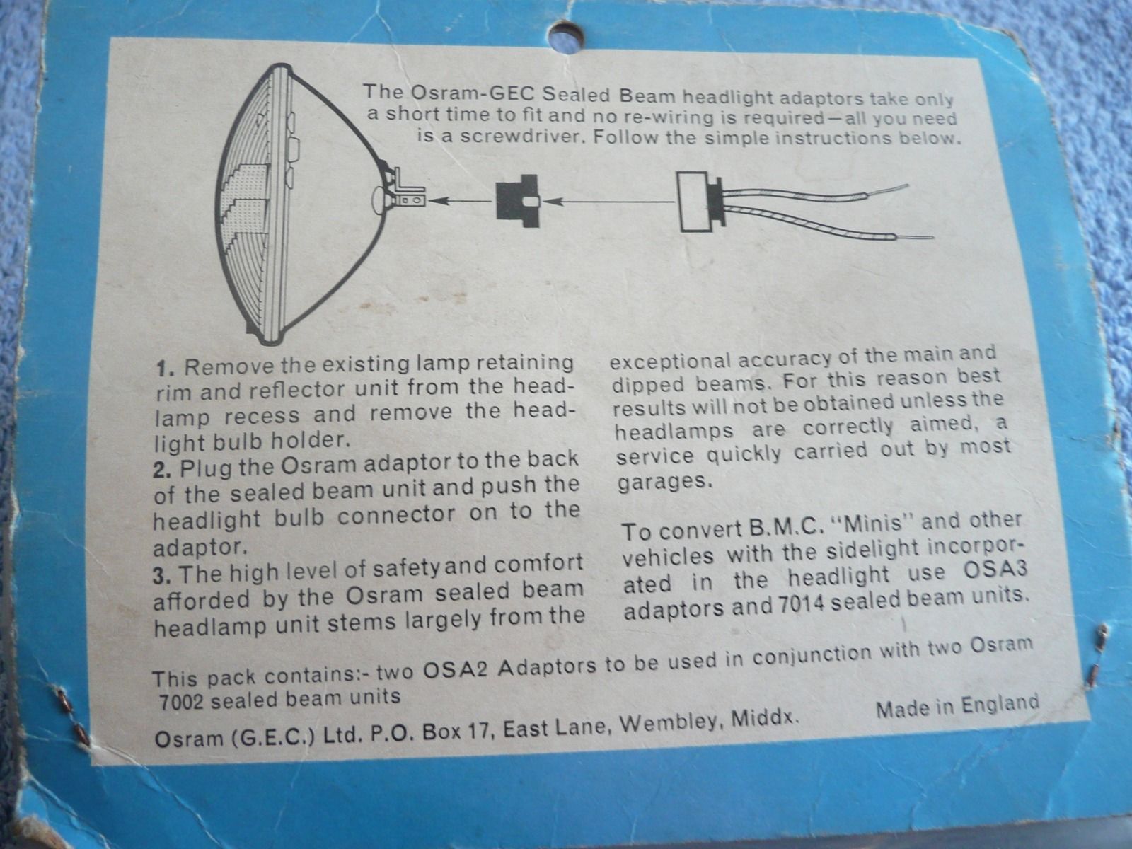
Horn Push fixation on XK 140 and 150
Leave a reply
Horn Push fixation on Steering Wheel for XK 140 and 150
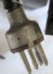
The Steering Column Control (Jaguar C.5531) is a Lucas manufactured assembly of a Top Cover with Lucas code 32902/E.

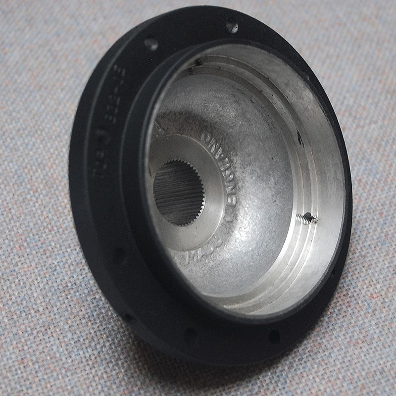
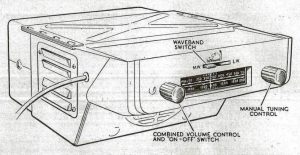
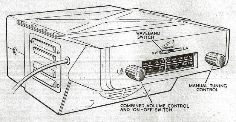
 Top cover assembly Lucas 32902/E Fixing Plate (Lucas 330614) at underside of assembly
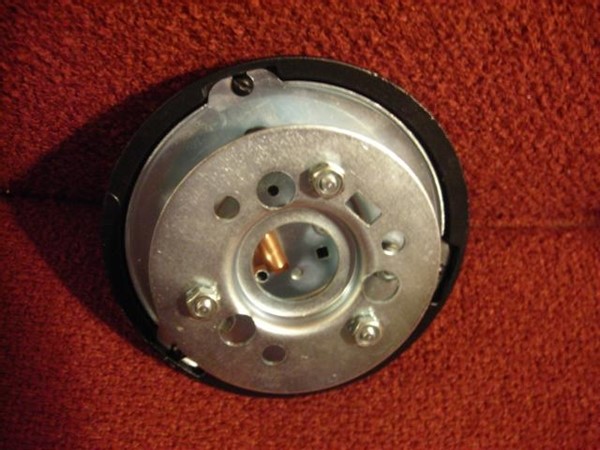
Part of this assembly is a Plate for fixing of Control (Lucas 330614) made of (zinc?) plated steel sheet of about 1 mm.
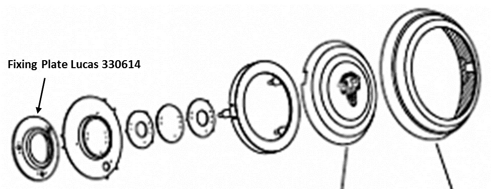
 Exploded view of Lucas assembly 32902/E with position of Plate for Fixing of Control 330614.
The complete assembly is fixed to the Steering wheel via this Plate 330614 by means of 4 Grub Screws C.1037 on the standard wheel and often 3 Grub Screws on wood rim steering wheel hubs. This Grub Screw has a part number that dates from 1938 or earlier.
 Example of steering hub with rim for Fixing Plate and 3 Grub Screws
The Grub screw has a hexagonal socket to be used with an “Allen” key (or “Inbus” in most countries) and a pointed tip. The point should hold the Fixing Plate in position whereby the 45⁰ angle should push the Plate down on an internal rim in the Steering Wheel centre (see photos above).
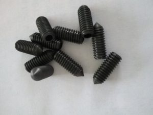 Grub screws with hexagonal socket and pointed cone

The original thread of the Grub screw is difficult to determine, but there are only 2 possibilities considering for this Grub Screw:
- 2BA Diameter 4.70 mm Pitch 0.81 mm Often used by Lucas
For reference the data of the following threads:
- UNF 10 – 32 Diameter 4.83 mm Pitch 0.79 mm Later introduction of UNF
- M5 Diameter 5.00 mm Pitch 0.80 mm “Continental” thread, not UK
The grub screw has an overall length of about ½ inch. Roger Payne mentions a length of 7/16″ but this might be experienced as a bit short as the complete grub screw normally enters far into the screw thread. Note that the original screw may well have been replaced meanwhile by another type. Especially “Imperial Grub screws” are not easy to obtain, but they are still out there.
The UNF 10-32 Grub Screw may be an alternative in the USA. The pitch is again 0.79 mm but the diameter is a little bit larger with 4.83 mm.
Fortunately, an M5 version is readily available everywhere and can be used as a replacement after the thread has been re-tapped with M5. This is feasible as the thread pitch is identical within 0.01 of a mm. Therefore, only the diameter of the threaded hole is increased from (worst case) 4.70 mm to 5.00 mm. The metrical version is readily available: search for DIN914 M5 x 12 or M5 x 16 as an alternative. They use a 2.5 mm Allen or Inbus key.
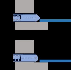 Only the Cone point (top picture) secures the Fixing Plate in a reliable way
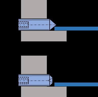
There are basically two types of Grub screws with hexagonal socket: with “Cone” point or ”Cup” point. The above picture makes it clear that this construction absolutely requires a “Cone” pointed version.
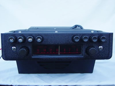
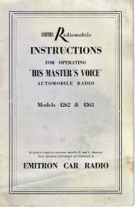
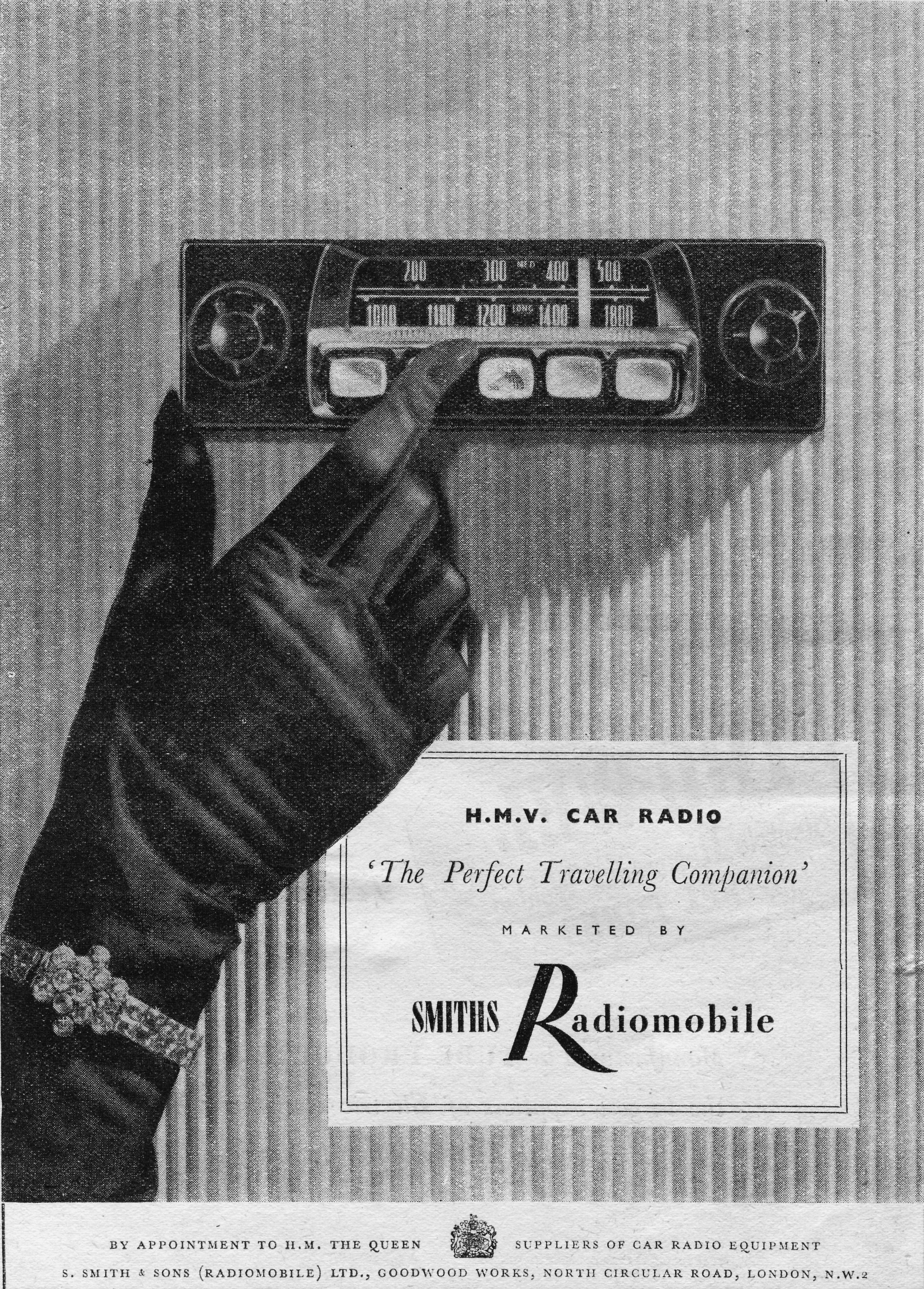
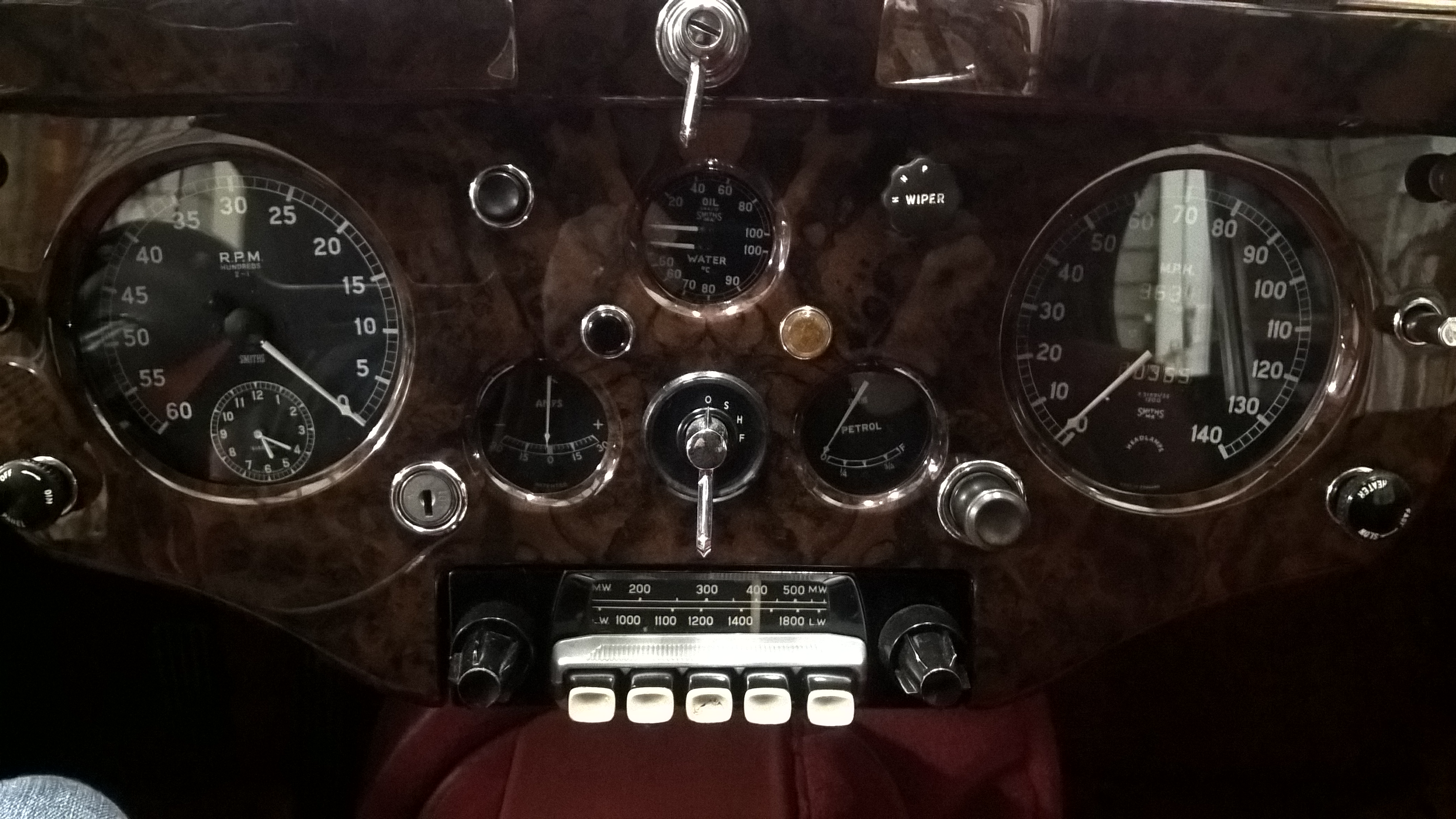
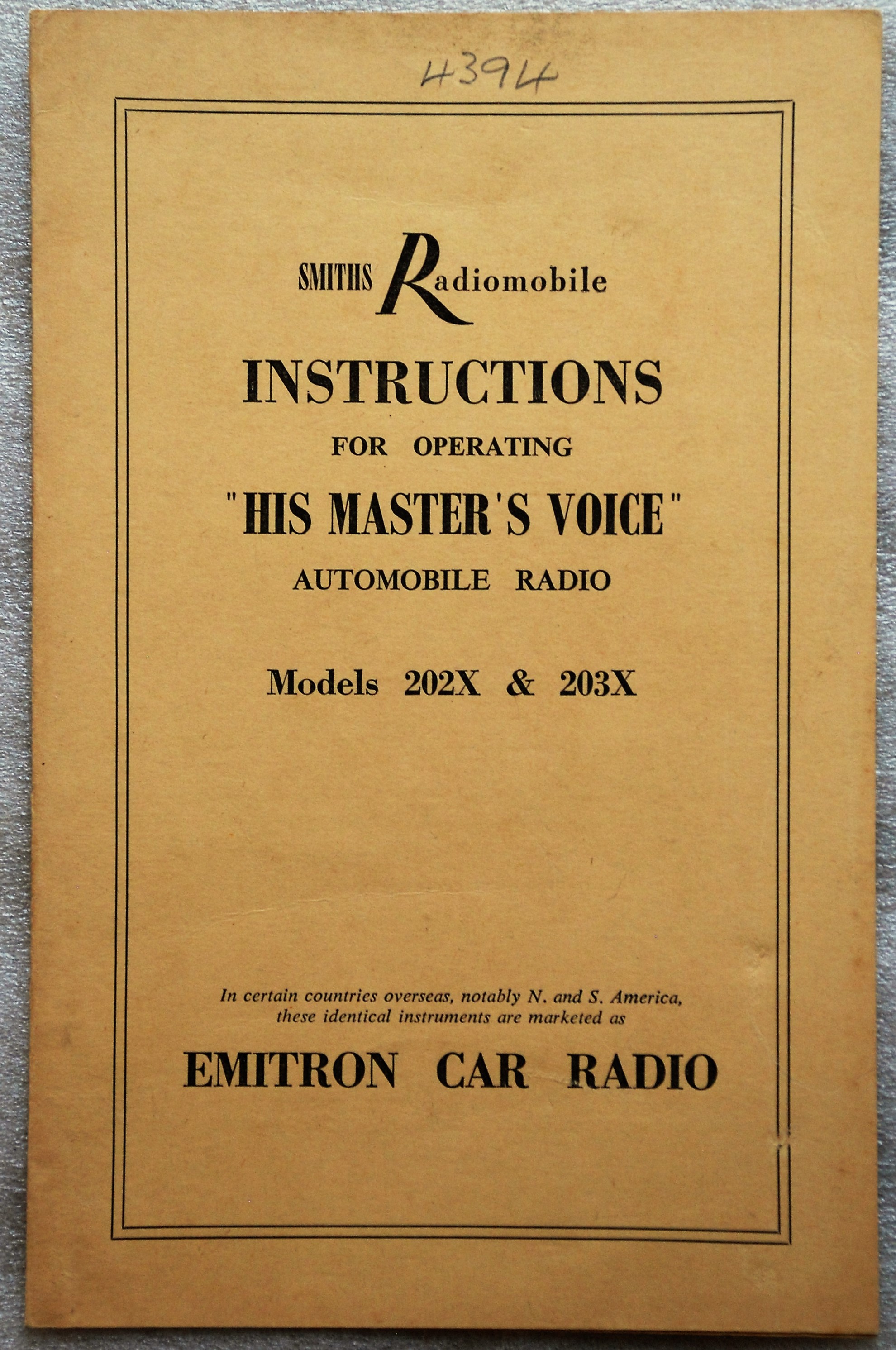
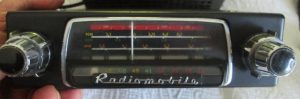
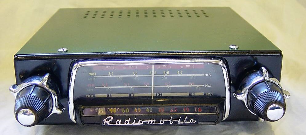
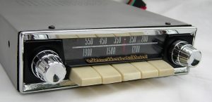
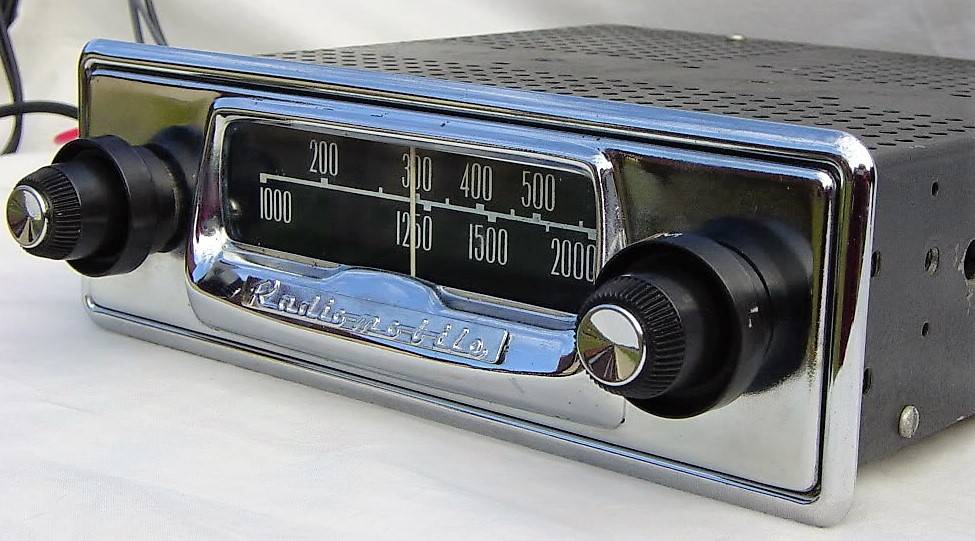
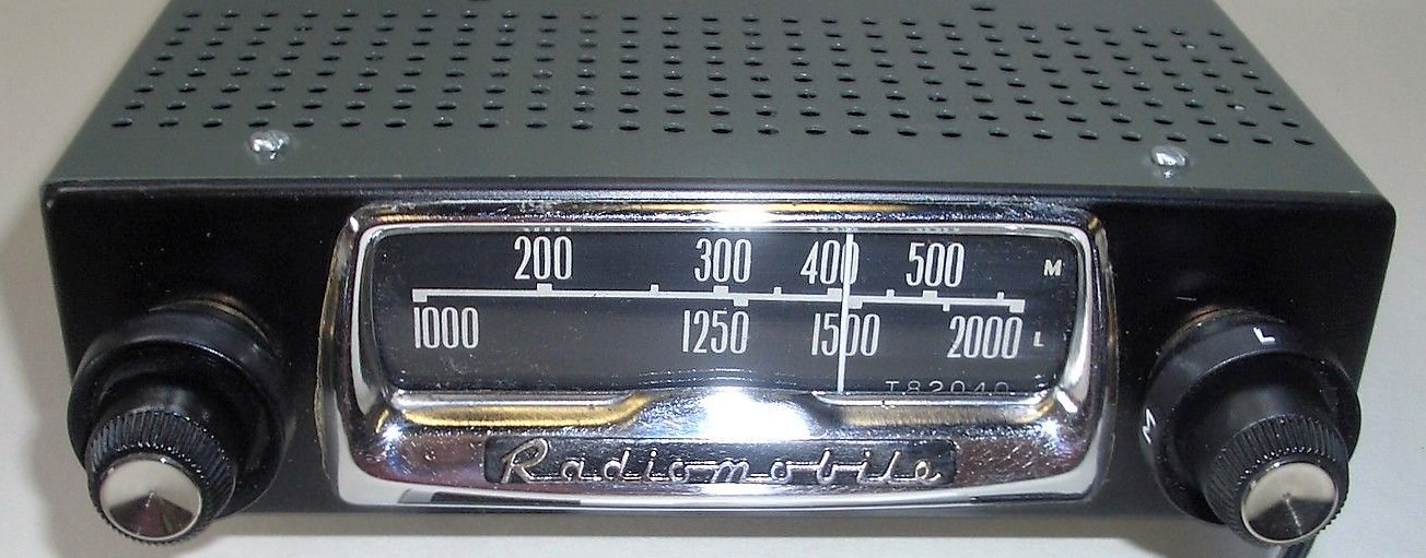
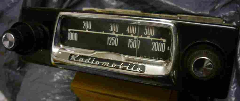
Radiomobile radios for Jaguars (1948 to1961)
Radiomobile radios for Jaguar’s (1948 – 1961)
(Click pictures to enlarge)
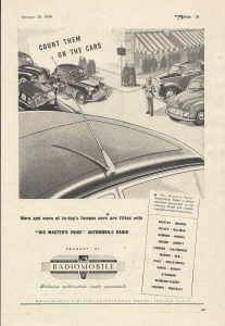
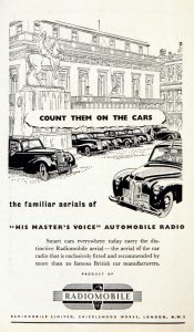
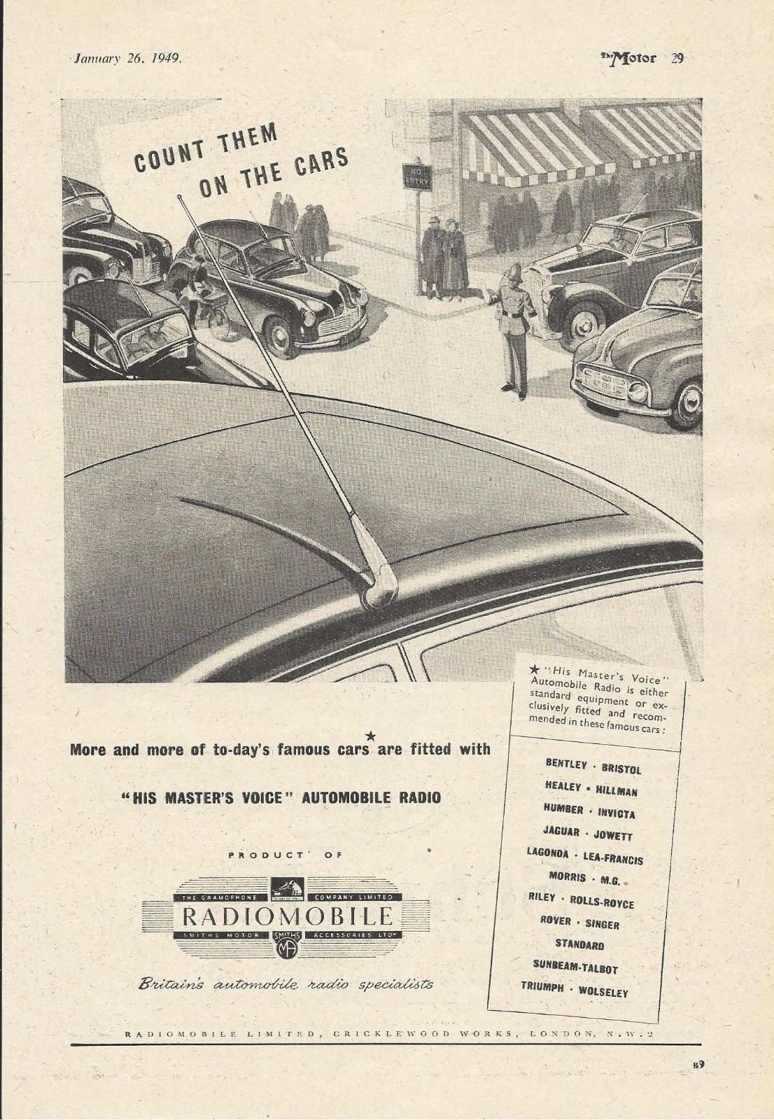
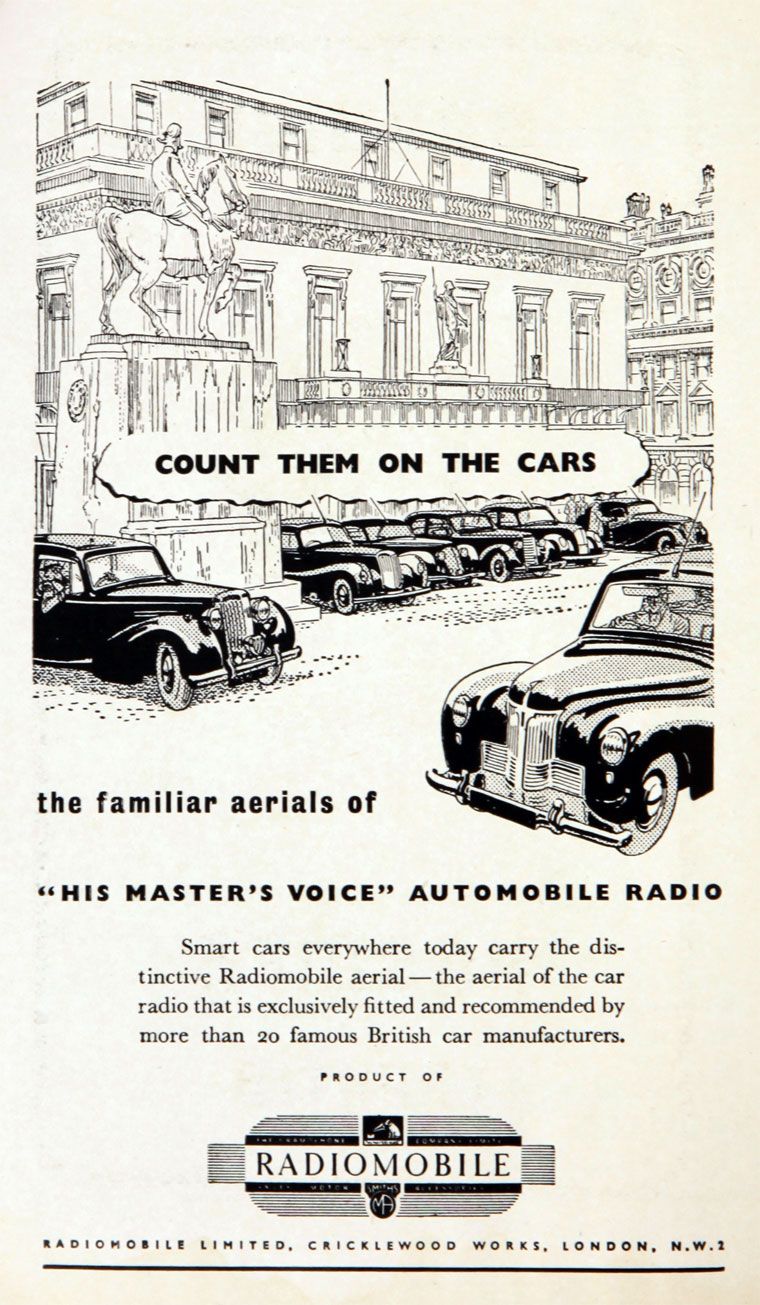
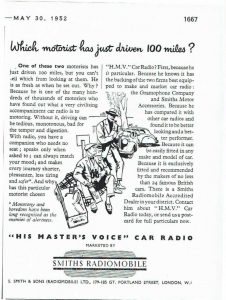 Early advertisements from 1949 to 1952

1. Introduction
After the war, Jaguar offered Radiomobile car radio systems as an “Optional Extra”. This article gives the history of the Radiomobile company and describes the radio systems fitted on Jaguar XK’s. As this survey started in the “pre-semiconductor” era, radio equipment used valves requiring a separate high voltage supply (over 200V!) placed in a box that was normally larger in size than the receiver unit itself. From about 1958 the first “transistorised” car radios appeared and miniaturization of equipment was about to start. We have to understand that these first transistor radios were in fact “hybrids” using a combination of valves and semi-conductors using a “semi-conductor” rectifier system and later some transistors.
We follow the development of the radios as used for the Jaguar XK 120, 140 and 150 over a period from 1949 till about 1961, but it is evident that the content also applies to contemporary Jaguar Saloon models.
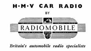
 The new official Radiomobile logo (left) showed the two parent companies HMV and Smiths Motor Accessories. The HMV logo (right) was shown on many Radiomobile models.
1.1 The Radiomobile company
Electric and Musical Industries (EMI) had been established in 1931 in the UK as the result of a merger between The Gramophone Company and The Columbia Graphophone Company. Next to recording and playing equipment, also radar and television were the outcome of extensive research activities within EMI. Radio manufacturing became one of their key businesses.
In 1945 EMI and Smiths Motor Accessories Ltd. established a new company named S. Smith and Sons Radiomobile Ltd. (with offices at Great Portland Street, London W1) essentially to sell car radios, initially manufactured and developed by The Gramophone Company, part of the EMI group.
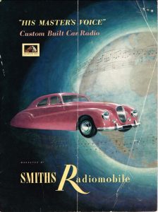
 Compare the 1953 brochures for UK (left) and USA (right): HMV name and logo removed due the rights of RCA in the US. Pictures Roger Payne


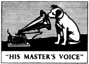
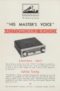
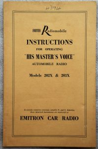
It was the intention of Radiomobile to use the His Master’s Voice brand name and call their radios HMV Car Radios and many radios therefore show the HMV name and/or emblem.
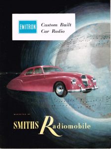
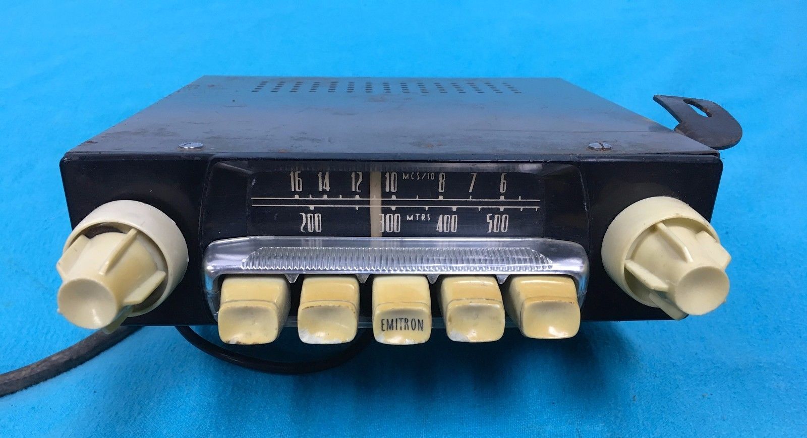
However, RCA in the USA still had the rights on the brand name His Master’s Voice for North and South America after they sold their share in EMI in 1935. It was thus not possible for Radiomobile to use the HMV brand name in the USA. Radiomobile radios fitted by Jaguar during production as an “Optional Extra” on cars destined for the USA were probably still branded as such with sometimes the HMV logo on the push-buttons. If a Radiomobile radio was fitted as an aftermarket product in the USA, these units were sold under the brand EMITRON. This brand name was owned and used by EMI for radio (component) exports to North & South America; EMITRON was also the brand name for radio valves and other electrical components manufactured by EMI and sold in the USA.
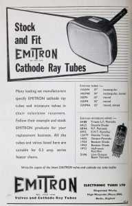 EMITRON as brand name for radio components

The official Smiths statement in their catalogues and brochures regarding this issue was: “In certain countries overseas, notably N. and S. America, these identical instruments are marketed as EMITRON CAR RADIO”. However, it seems that with the 1955 introduced 200 series the Emitron name had been dropped and all US destined versions were from now on Radiomobile branded, whereas in Europe (including UK) the two names (Radiomobile and His Master’s Voice) were used next to each other: the His Master’s Voice versions for the “high end” models only. The HMV brand name was eventually dropped in 1962 with the introduction of the 600 series, which only existed as a Radiomobile version throughout the world.
1.2 A survey of Radiomobile types from 1948 to 1961 as fitted on Jaguars
After the war the newly established Radiomobile company started the development and manufacturing of car radios. The following survey of 12 Volt Radiomobile car radios (using radio valves) should be seen as guidance only, as the precise dates of introduction of the various versions are often unknown, and radios still in stock may have been used in the Jaguar production of successor models. The application of models listed in Bold have been confirmed as “Optional Extras” in one or more Jaguar Spare Parts Catalogues.
- 1946 – 1951 100 Long & Medium Wave for Europe
- 1946 – 1951 101 Long & Medium Wave for Europe (no Tone Control)
- 1948 – 1951 4012 Medium Wave for N. & S. America and S. Europe
- 1948 – 1951 4014 Medium Wave for Australia & New Zealand
- 1949 – 1951 4050 Long & Medium & Short Wave for Rest of World
- 1951 – 1955 4100 Long & Medium Wave for Europe
- 1951 – 1955 4102 Long & Medium Wave for World excl. Europe
- 1951 – 1954 4200 Long & Medium Wave for Europe
- 1951 – 1954 4202 Long & Medium Wave for World excl. Europe
- 1953 – 1955 4260 Long & Medium Wave for Europe
- 1953 – 1955 4262 Long & Medium Wave for World excl. Europe
- 1953 – 1955 4263 As 4262 but 6 Volts
- 1953 – 1955 4300 Long & Medium & Short Wave for World excl. N.A. and Europe
- 1955 – 1958 200 X Long & Medium Wave for Europe
- 1955 – 1958 202 X Medium Wave for World excl. Europe
- 1955 – 1956 220 X Medium Wave for Europe
- 1955 – 1958 230 R Medium & Short Wave for World excl. N.A. and Europe
- 1956 – 1958 20 X Long & Medium Wave for Europe
- 1956 – 1958 22 X Medium Wave for Europe
- 1959 – 1961 40T Long & Medium Wave for Europe
- 1959 – 1961 41T Long & Medium Wave for Europe; polarity switch
- 1959 – 1961 42T Medium Wave for World excl. Europe; polarity switch
- 1959 – 1961 42TC Medium Wave for World excl. Europe; polarity switch; tone control
- 1959 – 1961 400T Long & Medium Wave for Europe
- 1959 – 1961 401T Long & Medium Wave for Europe; polarity switch
- 1959 – 1961 402T Medium Wave for World excl. Europe; polarity switch
- 1960 – 1961 50T Long & Medium Wave for Europe
- 1960 – 1961 51T Long & Medium Wave for Europe; polarity switch
- 1960 – 1961 52T Medium Wave for World excl. Europe; polarity switch
- 1960 – 1961 52TC Medium Wave for World excl. Europe; polarity switch; tone control
- 1960 – 1961 500T Long & Medium Wave for Europe
- 1960 – 1961 501T Long & Medium Wave for Europe; polarity switch
- 1960 – 1961 502T Medium Wave for World excl. Europe; polarity switch
We occasionally see an original Jaguar with a Radiomobile radio that is not on the official list of “Optional Extras” as listed in the various SPC’s. Remember that Radiomobile radios were also supplied and installed by Jaguar dealers afterwards. We mention e.g. the Radiomobile Model 4100 on the XK 120 and the Model 20X models used on the XK 150, which both were of a simpler design and may have been installed by dealers to save cost. For the latter, these models have been even included in the “Smiths Radiomobile Installation Instructions” for the Jaguar XK150. We have therefore included the description of several Radiomobile radios not formally recommended by Jaguar in this article.
When a radio was fitted by the Jaguar factory, a Radiomobile Operating Instruction folder and the Radiomobile Warranty card were included which had the Jaguars body number written on it in pencil.
1.3 Manufacturing facilities
From the early Thirties onwards HMV radio production was centred at EMI’s Sheraton Works in Hayes, 15 miles to the west of London. Radiomobile production of (HMV) car radios started in the existing Smiths Cricklewood Works, London NW2, a vast industrial site built in the 1920’s and continuously extended in the decades thereafter, housing various Smiths industrial activities including “Motor Accessories”. However, there are indications that the first HMV/Radiomobile car radios (100 series) have still been produced at Hayes.
The Cricklewood Works housed next to the Motor Accessories division three other Smiths activities: Industrial Instruments, Aircraft Instruments and the (well known) English Clocks production.
From about 1952 the production of car radios gradually moved to the new Smiths Goodwood Works, North Circular Road (Staples Corner) in London NW2, not far from the Cricklewood Works. The export division of Radiomobile stayed at Cricklewood, as we may conclude from various brochures.
2. Radio installations offered for the XK 120
2.1 Available “optional extras”
The following radios of the above listing were available for the XK 120 either as an “Optional Extras” over the period 1949–1954 or as a “dealer option”. The “Optional Extras” as listed by Jaguar have been indicated in Bold letters.
- Model 100 with Long and Medium Wave and Tone Control
- Model 101 with Long and Medium Wave, without Tone Control
- Model 4012 with Medium Wave for North and South America
- Model 4014 with Medium Wave for Australia and New Zealand
- Model 4050 with Medium and Short Wave
- Model 4100 with Long and Medium Wave
- Model 4102 with Medium Wave
- Model 4200 with Long and Medium Wave
- Model 4202 with Medium Wave
- Model 4300 with Long, Medium and Short Wave
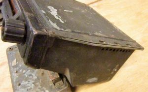
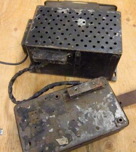
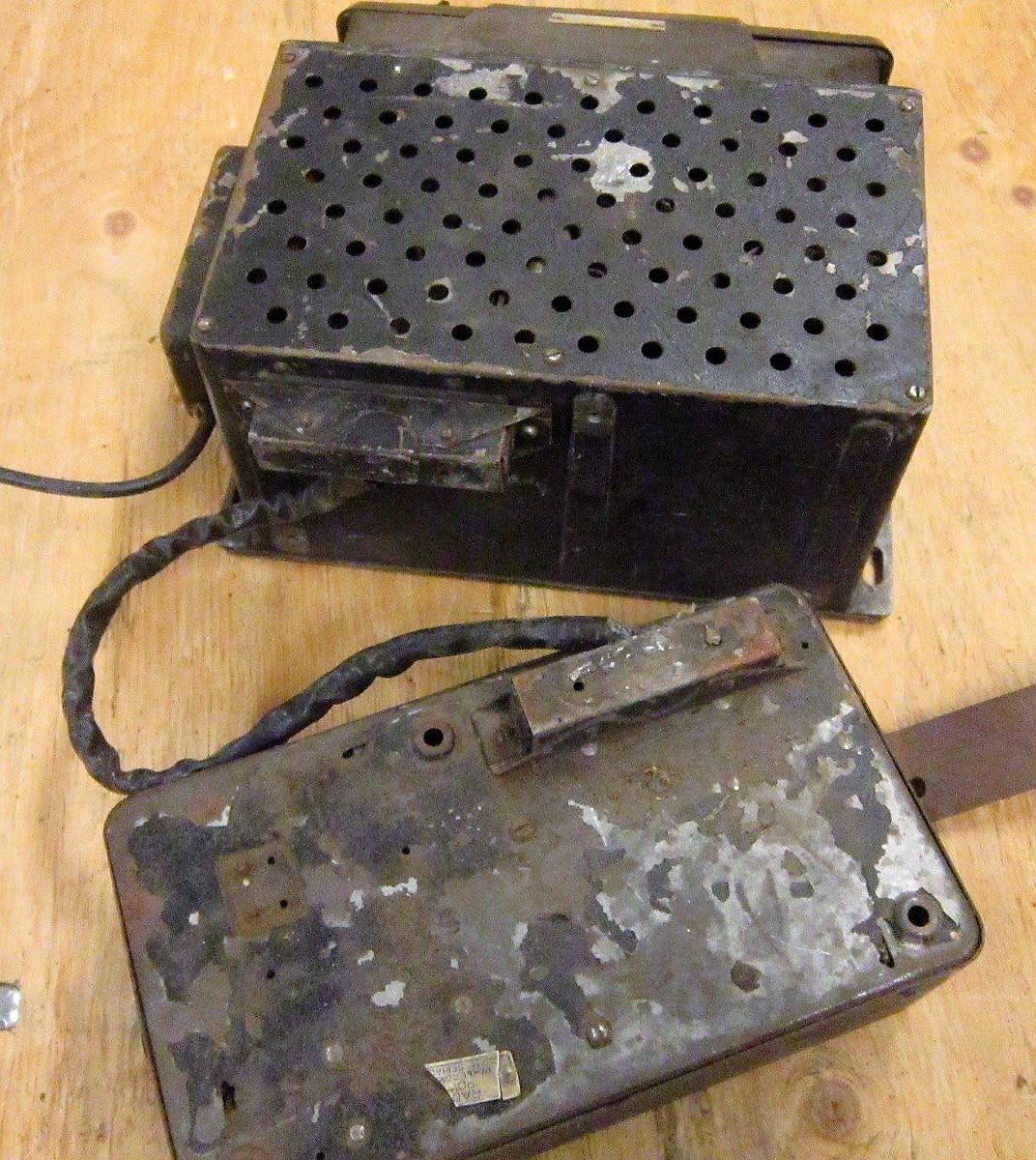
Note that the 100 and 4000 series both had a “single unit” construction consisting of a receiver (also called controller), a loudspeaker and a power supply (or amplifier) although the latter could be detached. Later generations starting with the 4100 / 4200 / 4300 series, were of the “3 unit” construction” (or also called the “Electrical Link” construction by Radiomobile): receiver in/under the dashboard and both speaker and amplifier remotely positioned either in the front or the rear of the car all connected (“linked”) via electrical cables.
2.2 Model 100 (1948 – 1951)
The first Radiomobile car radio was named Model 100 (manufactured from 1946-1951) and Jaguar initially used it from 1946 to 1948 in the 1½, 2½ and 3½ Litre Saloons. The Model 100 was only installed (as an option) on the OTS version of the XK 120. This Medium and Long Wave receiver was of the “single unit” construction. It received Jaguar part number C.4600. At the back of the receiver an amplifier unit was mounted (part number C.4601; Radiomobile code unknown) and connected via an external cable. The power output of this radio was 3.5 Watts and the 5” loudspeaker had an impedance of 5 Ohms. Normally the 100 was delivered in black (example shown below) but other colours for the front (escutcheon) were possible.
 Model 100 with its typical “single unit” construction, but the Amplifier at the back could be detached

Radiomobile supplied various colour combinations to the car industry to match e.g. the dashboard design. Radiomobile provided Bentley even with a wooden facia and a different scale. Note that the Jaguar versions for the 100 series were black (front and knobs) while other car manufacturers may have opted for other colours, knobs and scales.

 Bentley with wooden front Grey front and white knobs Beige front and white knobs


Radiomobile started to export these models throughout Europe in the early 1950’s.
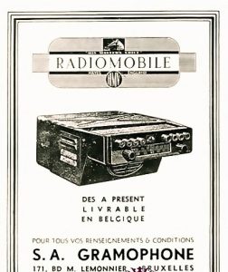 October 1948 Radiomobile advertisement for Jaguar Export: Belgian advertisement of RM 100


Model 101 was identical to the 100 but was supplied without Tone control and pre-set push buttons. This version was not in the Jaguar “Optional Extras” programme, but may have been installed by Jaguar dealers.
 Model 101 without Tone Control
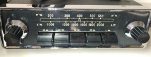
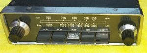
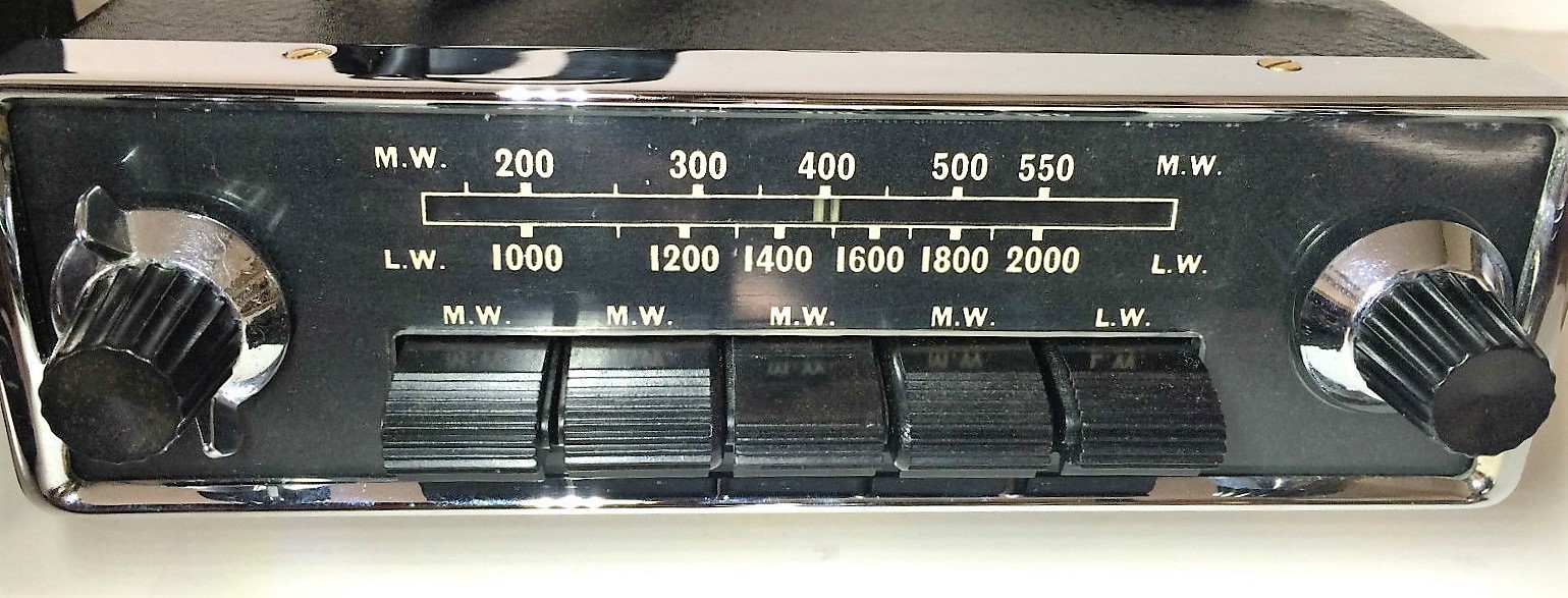
The 100 series were used in most European countries. Medium Wave radios in 1950’s Europe had a scale running from 200 to 550 metres and a Long Wave scale from 1000 to 2000 metres.
2.3 Model 4012 & 4014 (1948 – 1951)
The Model 4012 with Medium Wave was used on the OTS version of the XK 120 in North and South America and some Southern European countries. Whereas in Europe the Medium Wave frequency spectrum had been defined starting from 531 kHz to 1600 kHz, in North America the upper limit run up to 1700 kHz. The radio on the photo below has the MW scale in MHz/10 (instead of metres), running from 16 to 6 so it may still have been a European version. The 4012 used the same power unit as the Model 100 radio and had Jaguar part number C.4608.
 Radiomobile 4012 with MW only
The Model 4014 (Jaguar part number C.4609) with Medium Wave was only used in Australia and New Zealand. In Australia MW radio broadcast allocation was from about 1700 kHz to 535 kHz. Note that radios sold in Australia normally had a special dial face per state with local radio station-codes printed on it.
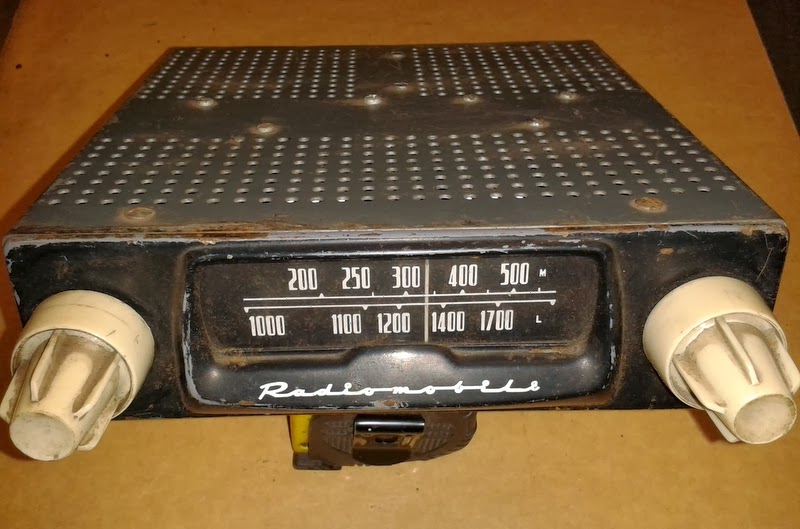
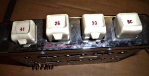
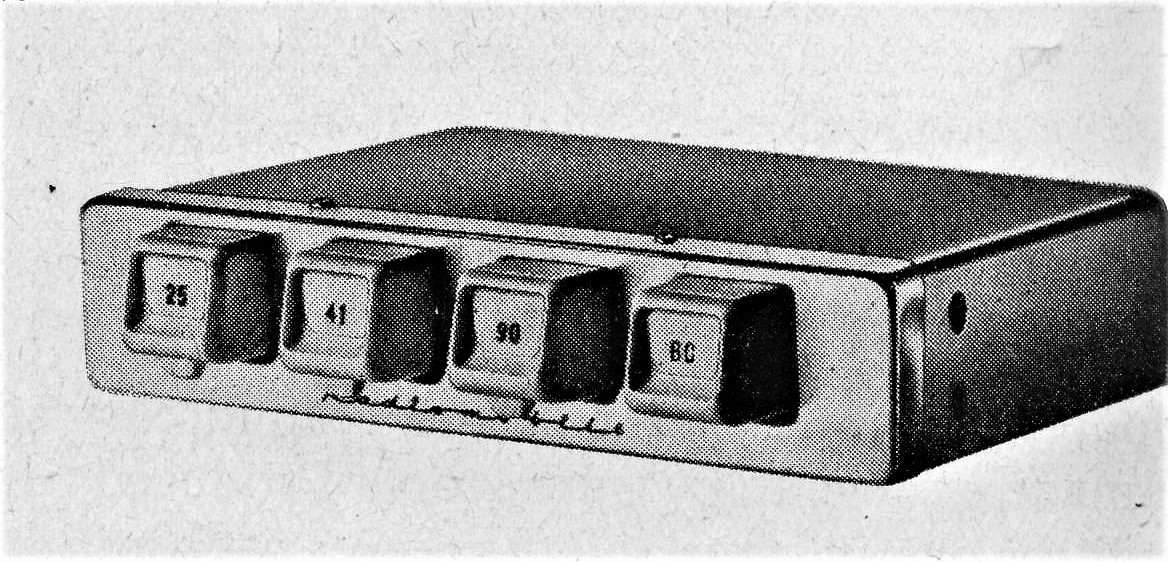
2.4 Model 4050 (1949 – 1951)
In the autumn of 1949 Radiomobile introduced its first car radio with Short Wave, in addition to Medium Wave. There were 7 Short Wave bands, each with a separate indication on a drum-type tuning scale.
Although part of the “single unit” construction range (like the Model 100) the front of the 4050 was clearly different. It had 4 push buttons (to pre-select Medium Wave stations) positioned below the scale. The “Tone-Control” was done by one turning knob with 4 positions instead of the two tone-control push buttons of the Model 100 version. Apparently the 4050 had the possibility to install a remote speaker.
Model 4050 (Jaguar part number C.4610) was destined for many countries but not for the main markets such as Northern America and Europe and only used on the OTS model of the XK120 (and other contemporary Saloons). Note that the 4012, 4014 and 4050 have sequential Jaguar part numbers.

 The rare Model 4050 model with 4 push buttons Side view of receiver

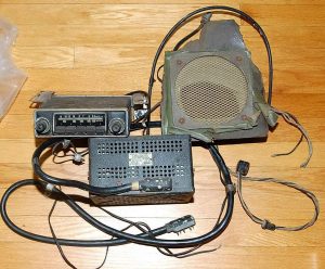
 Complete set with receiver (top) and amplifier (bottom)
2.5 Installing the 100 and the 4000 series
If an optional radio had been ordered, Jaguar removed the map drawer of the DHC or FHC version and the radio tuner was installed in its place using special brackets. On the earlier XK 120 DHC/FHC models the wood panel opening had to be widened but cars produced after 31st December 1951 were made with the correct width for the radio receiver: 2 x 7 inch (51 x 178 mm) typically. Remember that the aforementioned versions for the XK 120 OTS were all of the “single unit” construction.
Radiomobile provided instruction booklets for the installation of car radios. For the 1951 successor models (see next chapter) specific instructions are available for the XK 120 models. Instructions do exist for the “Jaguar Mark V 1950-1951 Saloon and Coupe models“, published in May 1951, possibly covering the RM100 and 4000 series. In addition, there is one for “Jaguar Mark VII 1951 models“, published June 1951. (Information: Roger Payne).

Fitting a Model 100 under the dashboard of an early Saloon(left) and an Austin 12/16 (right) where the amplifier unit has been decoupled and is positioned above the receiver. Note: roof aerial for both cars!
2.6 The 4100 series (1951 – 1955)
Although not part of the “Optional Extras” list of Jaguar, the 4100 series can still be found on Jaguars as it was around 25% “less costly” than the 4200 series and (apparently) offered by Jaguar dealers. It was produced in parallel to the 4200 / 4260 models and may therefore have been used on early XK 140’s as well. Radiomobile referred to the series as having “High Sensitivity” whereas the 4200 and 4300 series had “Super Sensitivity”.
The Model 4100 had LW and MW reception, but only 3 push-buttons instead of the 5 buttons of the 4200 series. It used the same Amplifier Unit as used for the 4200 and 4260 series: only the low power 46028A version was recommended for this receiver. For more information, see paragraph 2.9.
Another version in the 4100 series was the Model 4102, similar to above but with MW only. US Jaguars may have had this particular version installed (branded as Emitron 4102) as LW radio wasn’t required in the USA.
 Radiomobile Model 4100 in black. The HMV logo is missing on centre button. Model 4100 in an XK 120.


2.7 Model 4200 & 4202 (1951 – 1954)
In July 1951, an improved version of the Radiomobile 100 and 4000 series became available: the 4200 series. This range was used from 1951 till about 1954. Models that have been offered on the XK 120 are the Model 4200 and Model 4202, introduced on the FHC models in 1951. At the same time the OTS got this radio option replacing the older types and it was also available on the DHC from 1953 onwards.
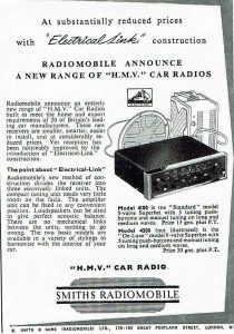
Model 4200 (with Jaguar part number C.5363) was a Long and Medium Wave receiver, in fact replacing the Model 100 version. It was the first of the “3-unit construction” replacing the “single unit” of the 100 and 4000 series. It had 5 push buttons: 4 for pre-selected MW stations and 1 for selecting the LW band. The face was black with a chromed rim and knobs available in various choices. This “standard” version is shown here below.
 Two examples of Model HMV 4200

The total power output of the radio system could be increased by opting for a “heavier” Amplifier. Radiomobile offered 2 versions: A-type and B-type of which the latter version was recommended and used by Jaguar. The complete car radio is therefore sometimes referred to as Model 4200B.
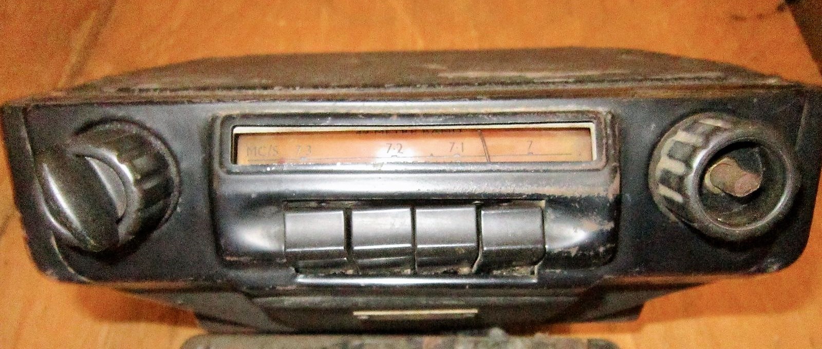
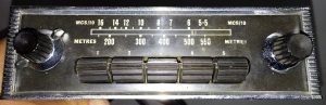
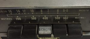
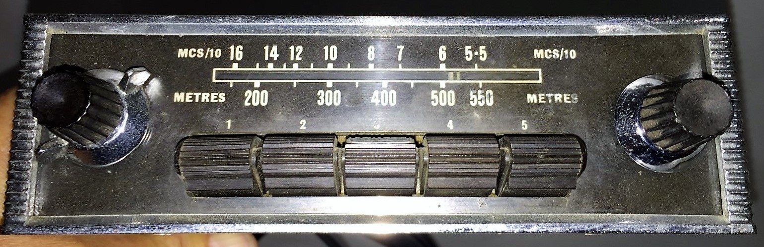
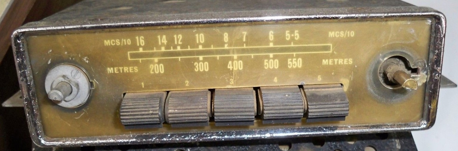
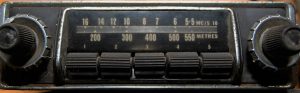
Model 4202 (Jaguar part number C.5370) was a simpler version of Model 4200 with Medium Wave only. Note that the scale is in Metres and MCS/10. Compare the 4202 front below with that of the 4200 shown above. This version was only available in 1952-1953. The Emitron 4202 version for America was manufactured in a dedicated Jaguar version with the text “EMITRON JAGUAR CUSTOM” instead of the scale indication in Metres (which seems logical for the USA). See also “Original Jaguar XK” by Philip Porter, page 65 of the 2003 edition.
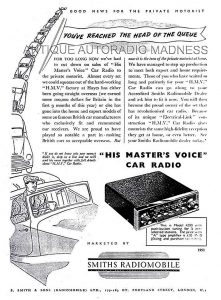 Smiths Radiomobile 1951 and 1952 advertisements introducing the first radios of a “3-unit” construction


 Model HMV 4202 in black Different front Model Emitron 4202
2.8 Radiomobile Model 4220 & 4222
Radiomobile also made ‘brand specific models” on basis of the 4200 series. Model 4220 is such an example, specially made for the Rover P4. The receiver part was positioned vertically and the loudspeaker was placed next to the receiver positioned behind gauze, while the (standard) remote amplifier was connected via a cable with connector plugs. The 4220 series has been derived from the 4200 series,
There were (at least) two versions: Model 4220 with MW and LW and Model 4222 with MW only. Both used the Amplifiers of the 4200 series (see 2.10)
 Typical arrangement of the 4220 series
 Model 4220 with MW & LW


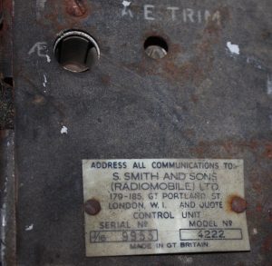 Model 4222 with MW only


2.9 Radiomobile Model 4300 with Long, Medium and Short Wave reception (1954 – 1955)
Although listed for the XK 120 in the Spare Parts Catalogue this radio was in fact more used on the XK 140 and therefore further detailed in chapter 3.
2.10 Amplifier units for the 4200 series
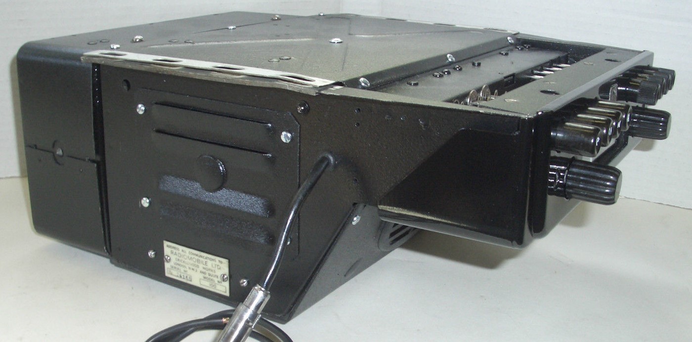
The 4200 series radios had a separate, remote Amplifier unit. There were two different versions of the Amplifier unit:
- Medium output version Type A with nominal 2.5 and maximum 3 Watt output for one loudspeaker
- High output version Type B with nominal 6 and maximum 7 Watt output, suitable for one or two loudspeakers.
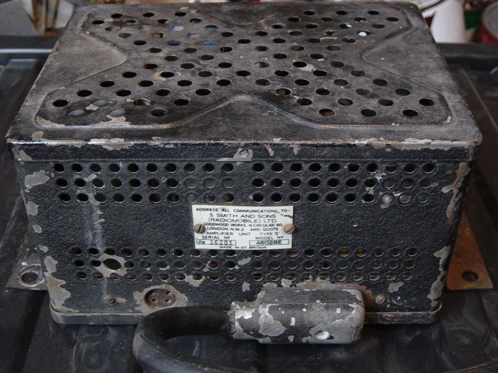
Radiomobile numbers are 46028A and 46028B respectively. There is also a Type E amplifier (coded 46028E) of which the exact application is unclear. Note that Jaguar only used the 46028B version with their part number C.5364.
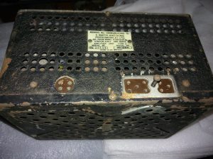
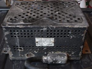 An 8 pin connector cable was used for 46028 Amplifier units.
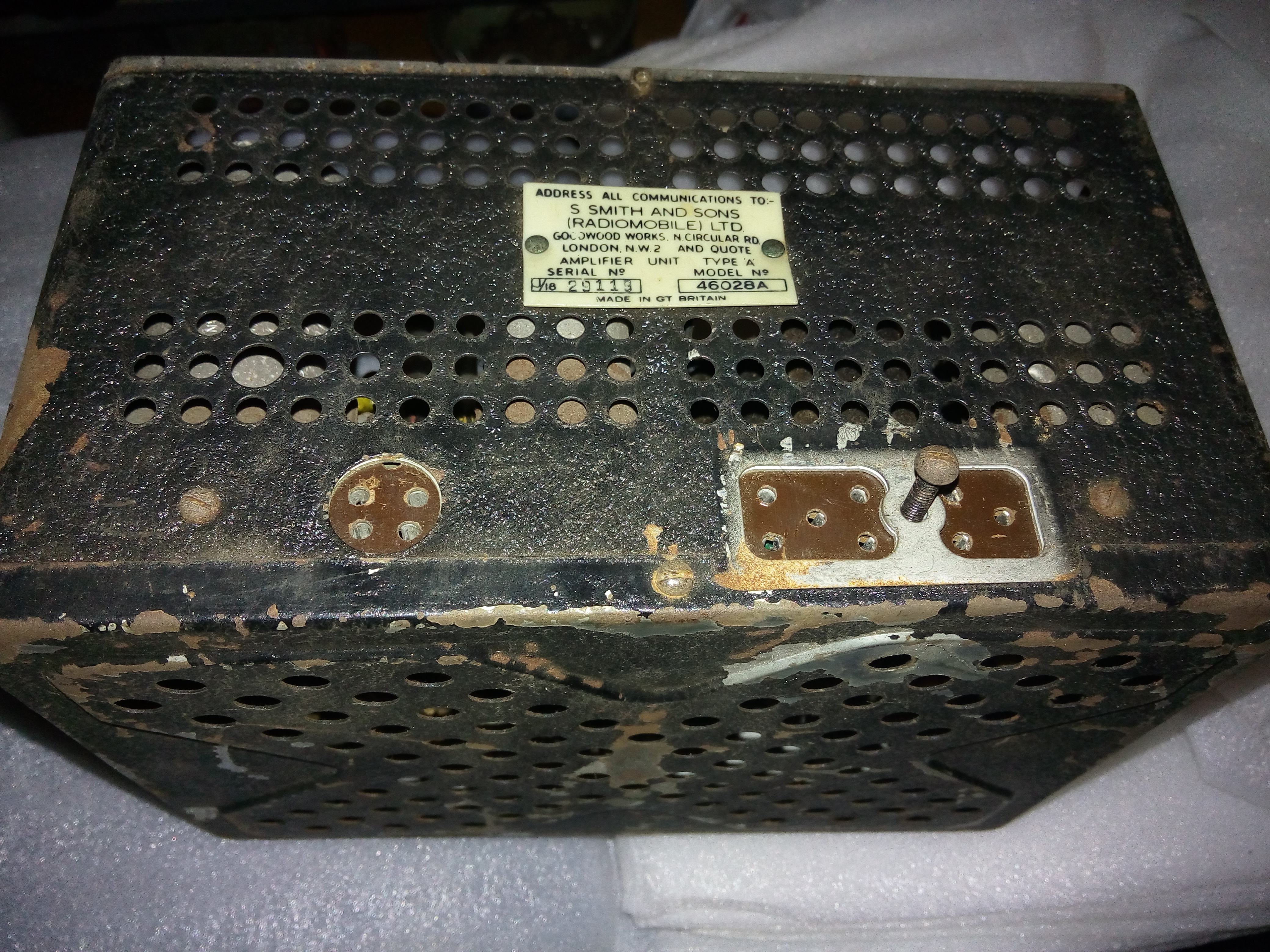
The first generation Amplifier Units had an 8-pin connector system for the cable from Receiver to Amplifier. This system was used for all “3 unit constructions” up to 1955. As we will see in Chapter 3, later generations “3 unit constructions” used a 5-pin connector system and the two generations are therefore not interchangeable! The loudspeaker connection of the first generation used a 4-pin connector and cable; the second generation had a 3-pin system.
2.11 Installing the 4200 series
A small 8-page booklet was published by Radiomobile in January 1952 giving detailed “Installation Instructions for His Masters Voice Automobile Radio Models 4200-4202 Series Smiths Radiomobile“. An instruction booklet exists specifically for the “Jaguar XK 120 Sports 1951 and 1952 Models“. Remember that the XK120 FHC had only been introduced around July 1951.
As mentioned before, early XK 120’s required widening of the drawer opening in the wooden dashboard to mount the Receiver unit. Cars produced after 31st December 1951 have the correct opening dimensions.
The 4200 series were the first of the “3-unit construction” generations and rather different from the previous 100 and 4000 series.
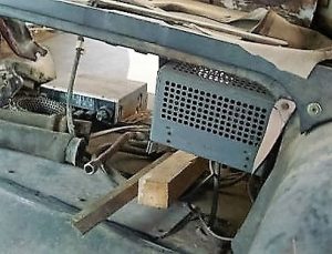
 Original 1954 amplifier installation between the Batteries


Note the early Radiomobile mounting bracket with single slit. (Photo’s Rob Reilly)
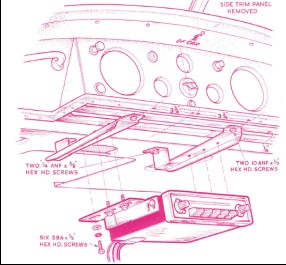
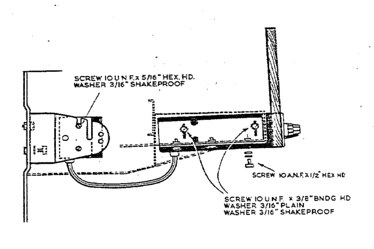
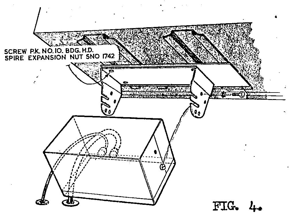
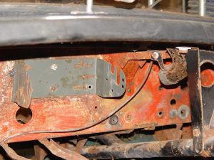
The Receiver (or Controller) was positioned in pace of the drawer for the DHC/FHC models and below the instrument panel on the OTS version using special mounting brackets (see picture below). As we will see there are three different brackets used for Amplifier mounting between 1951 and 1958:
- Bracket with single slot per side. Radiomobile code unknown.
- Bracket with double slots per side. Radiomobile code RMO3451/BA and/or RMH93508. Jaguar C.11797
- Brackets with no slots for Transistor Amplifiers. Radiomobile code RMO3320/K
The DHC/FHC versions had the Amplifier (or Power unit) placed between the two 6 Volt batteries (positioned behind the seats) using the standard Radiomobile bracket supplied with the unit. The Amplifier unit has 3 sets of screw holes and can be attached at 3 different positions: wall mounted, shelf mounted or under the instrument panel.
 Early mounting bracket with single slits, positioned between batteries (Picture Roger Payne)

A long cable (with 8 pin connectors at both ends) runs from the amplifier to the receiver. The routing of the Amplifier cable is as follows: from the Amplifier Unit (mounted between the batteries) first horizontally to the front of the car at the left side of the transmission tunnel, secured by a “P” clip halfway the tunnel. The cable continues forward following the firewall upwards to the rear of the Receiver. The complete cable is hidden under carpets. See picture above right.
The OTS model often had the Amplifier mounted directly in front of the Radio Control up against the bulkhead, using the standard bracket provided with the unit. The Amplifier cable was much shorter then.
 Special brackets for XK 120 OTS model. Loudspeaker plug with 4 pins on earlier Amplifiers
Cars built after 31 December 1951 had mounting holes pre-drilled and fitted with rubber blanking plugs if no radio installed by factory. The loudspeaker was located behind the seats. Another cable (with one 4-pin connector) connected the speaker with the Amplifier.
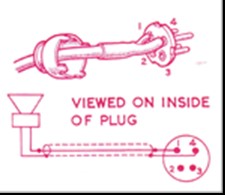
Although there are 4 pins on the plug, only 2 wires are used for connecting a loudspeaker. For the connection, we have to make a distinction between Amplifiers of Type A and Type B.
- For Type A amplifiers a speaker with impedance between 3 and 5 Ohms is connected to pins 1 and 2.
- For Type B amplifiers a speaker (or a combination of 2 speakers in parallel) with impedance of 2 to 3 Ohms should be connected to pins 1 and 3. For a (combined) speaker impedance of 4 to 5 Ohms pins 1 and 2 are used.
2.12 Price levels of 4100 and 4200 radio series
The Radiomobile brochure of August 1953 provides insight on the UK price levels of “aftermarket” radio sets per car model excluding installation cost. For the XK 120 Jaguar recommended Model 4200B with a total “kit” price of almost £41 (inclusive of purchase tax). As a reference: a complete XK 120 could be obtained for an amount around £1600 meaning the radio was at least 2.5% of the total cost. The simpler Model 4100 version had a kit price about £10 (about 25%) less than the 4200 series, which may also be the reason this model was rather popular with Jaguar customers.
The 1953 US price list shows two different radios: one for $115 (probably the Emitron 4102 with A type amplifier) and the other for $164 (probably Emitron 4202 model with B type amplifier). A complete XK 120 was between $4000 and $4600 depending on model and executions. The cost for the optional radio was thus between 2.5 and 3.5 % in the USA.
3. Radio installations offered for the XK140
3.1 Available “optional extras”
Whereas the “Salesman’s Data Book” for the XK 120 didn’t mention any radio as Optional Extras, the version for the XK 140 listed three different radio options:
1. Model 4260 with Long and Medium wave
2. Model 4262 with Medium wave only
3. Model 4300 with Long, Medium and Short wave reception.
 Page from Salesman’s data book: HMV 4260/4262/4300 (own photo)
The XK 140 Salesman’s data book had been edited late 1954 on the occasion of the XK 140 introduction as announced on 13th October 1954. Some of these radio models had been replaced late 1954 or early 1955 by versions listed below and we know that many XK 140’s had these later models, but a few 1954 and early 1955 XK 140 models may have these older types. It may also have happened that later XK 120’s had one of the above-mentioned radios installed. Apparently, the 4200 series never received Jaguar part numbers: none of the relevant SPC’s lists these radios. This is rather remarkable, as Jaguar even published UK retail prices for 1954.
In fact, none of the XK140 SPC’s listed any radio available as Optional Extras. There is sufficient hard evidence, however, that the 200 series have been applied on the XK 140 and Jaguar part numbers have been listed in other SPC’s.
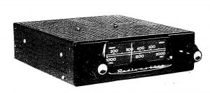
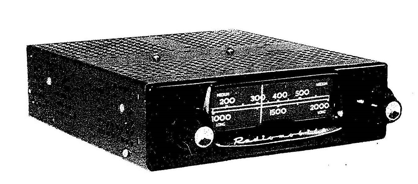
- Model 200X with Long and Medium wave
- Model 202X with Medium wave only
- Model 230R with Medium and Short wave reception
Like the 4200 series of the later XK 120, the new HMV Radiomobile radios used on the XK 140 had a receiver, an amplifier unit and a loudspeaker as well as a (long) cable between receiver and amplifier and smaller leads to the loudspeaker.
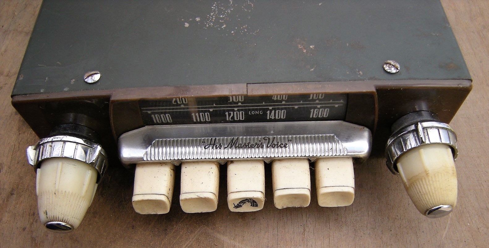
3.2 Model 4260 with Long and Medium wave (1954 – 1955)
The Model 4260 was a LW & MW receiver basically identical to its prececessor model Model 4200 but the design had been upgraded: the flat front and dial of the 4200 series had been replaced by a chromed rim around the scale and push-buttons. Jaguar still used the black knob and button versions for the XK 140 models, although there are indications that the Mk VII (M) versions may have had cream knobs and buttons.

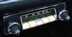 Two examples of HMV Model 4260 with cream or black knobs and push-buttons
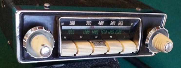

3.3 Model 4262 model with MW only (1954 – 1955)
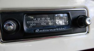
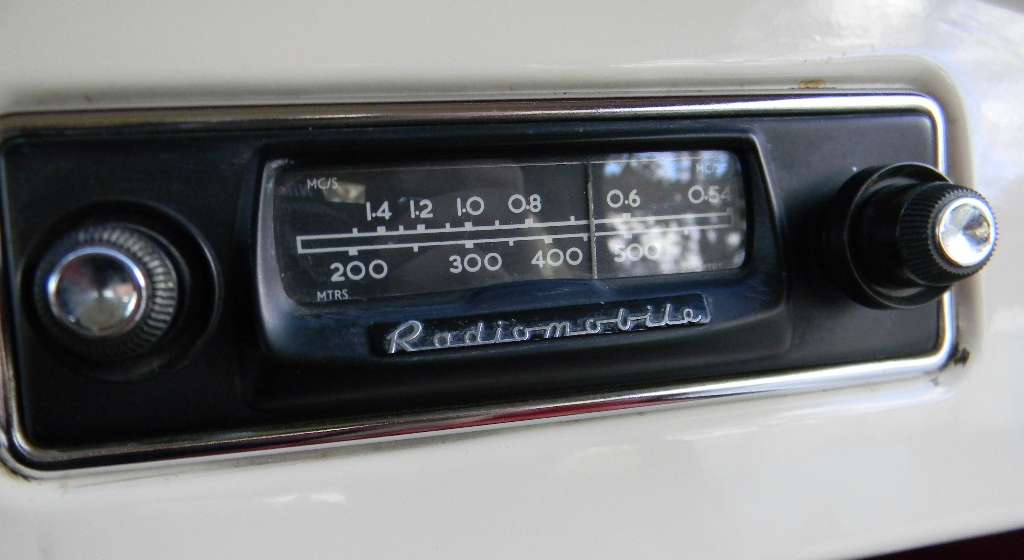
This is a medium wave only radio, with 5 pre-set buttons. All knobs and buttons in black as (most likely) applied for the XK 140 models. The Medium Wave dial showed Metres and MC/S/10 (or better MHz/10) to get the same impression as the two lines of the Model 4260 receiver with one scale for MW and another for LW. Most “MW only” Radiomobile receivers use the same method for their dials.
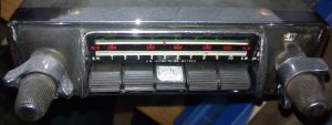
 Model 4262 with black knobs and push-buttons
As stated above, the Model 4262 of the Mark VIIM probabaly had cream push buttons and knobs, as can be seen in the photo below.
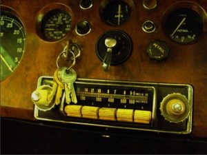
 Model 4262 in a Jaguar Mk VII Complete system Model 4262


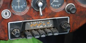
Note that Model 4262 had a specific way of choosing the “pre-sets”, using a screw located behind the front of a push button that had to be removed. See Instructions below.
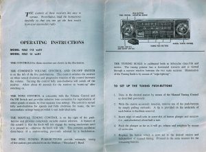 Instructions for Model 4262 dated February 1954 (Courtesy Roger Payne)

3.4 Model 4300 with Long, Medium and Short Wave reception (1954 – 1955)
The Model 4300 was the “high end” model of the 4260 series with Long, Medium and Short Wave reception and it superseded the Model 4050. Although technically related to the Model 4260 and 4262, this version was continued after the 1955 introduction of the Model 200X and 202X (replacing the Model 4260 and 4262).
 Model 4300 in black

3.5 Amplifier units
Two types have been used for the 4260 and 4300 series in the XK 140: Medium Output Type A with a 2.5 Watt output and the High Output Type B model with 6 Watt maximum output. This is a continuation of the Amplifier Units as used for the 4200 series with the 8 pin connector system. Further information: see paragraph 2.9.
3.6 Installation of the 4260 and 4300 series in the XK 140
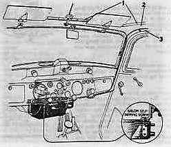
All radio’s mentioned above were of the “3 unit construction” consisting of a receiver (or controller), an amplifier (or power unit), connected via a thick cable with special 8-pin plugs at both ends, and a loudspeaker. The radio receiver part of the XK 140 was always mounted under the dashboard: for the DHC and FHC instead of the drawer, probably using special brackets replacing the original drawer brackets and slides.
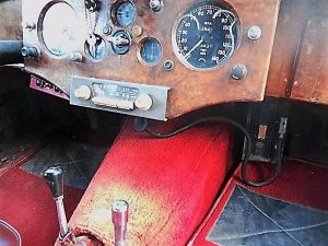
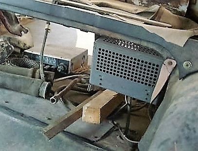
The OTS version had the large separate amplifier (or power unit) mounted high under the dashboard on passenger side as was the speaker (facing down).
 Later brackets have two slits for horizontal mounting of the Amplifier (Picture provided by Roger Payne)
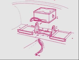
For the DHC and FHC the amplifier unit was mounted on a steel bracket RMO 3451/BA fixed under the parcel shelf at the LH side of the car.
In case of the DHC the speaker is mounted under the glove box, just as it was for the OTS versions. For the FHC the speaker was mounted in vertical elongated holes forward of the wing vent openings in the side panels. These black bitumen card trim panels actually had a perforated section that could be removed for the loudspeaker. Once the piece was pushed out, perforated aluminium was riveted over the hole on the rear of the panel. The possibility to have speakers on either side probably relates to the different driver positions in case of RHD or LHD cars, although the 7 Watt “High Output” amplifiers could also have two speakers installed.
In case the amplifier unit of the original Smiths Radiomobile is mounted under the parcel shelf in the boot, the (heavy) connecting cable runs under the floor to the radio receiver.
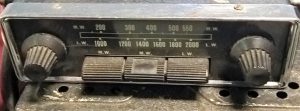
3.7 Model 200X with Long and Medium wave (1955-1957)
The new 200 series, introduced in January 1955, were the successor of the 4260 series and had a more “modern” design with a new HMV logo, but still with 5 push-buttons.
 Introduction of the new Model 200X
The 200 series consisted of two different basic versions indicated by the letter corresponding with the Amplifier used: XB or RB. The Model 200X (as shown below) was combined with the XB power unit.
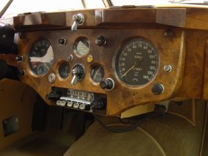
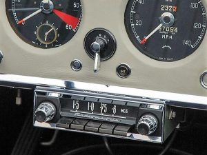
 Model 200X in an XK 140
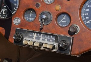
The receiver units have the same “looks” and only the type plate will tell whether it’s a X or R version. For the 200 series receivers, the 4 buttons acted as MW pre-sets and the 5th for choosing LW stations (no pre-sets).
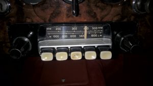
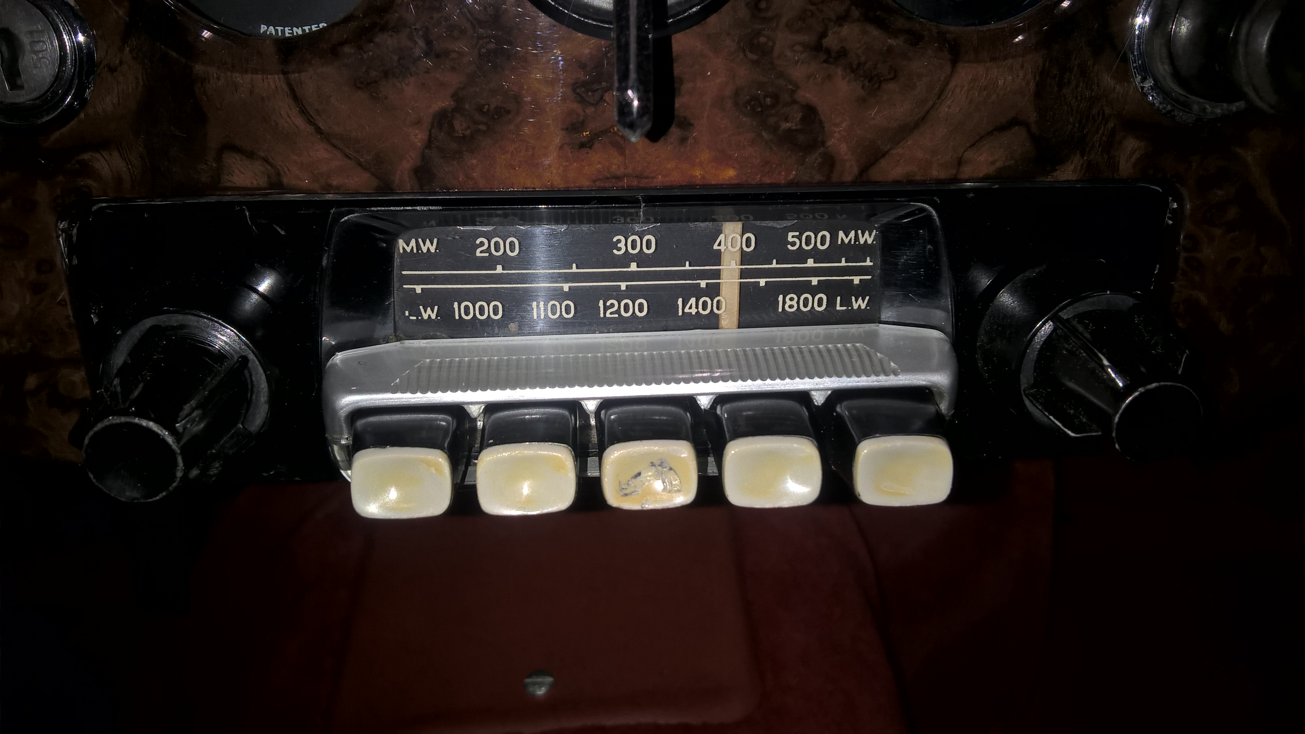
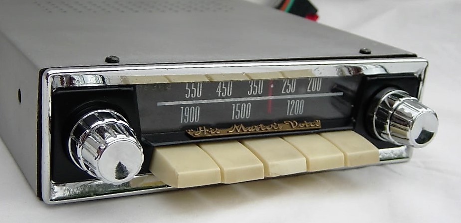
Jaguar used a specific receiver version with Radiomobile code RMH200X/VP and Jaguar part number C.11791. Radiomobile offered various choices for push buttons and turning knobs: full black and full white( cream), but also black push buttons with white fronts were an option. And Radiomobile also provided a choice of scales in white/white figures or white/red figures.Some radios had a chrome rim around the front.
Jaguar listed the RMH200X/VP version whereby the letters VP indicate the factory code for dial and knobs/buttons execution. There is ample proof that Jaguar factory-installed radios for the XK’s had fully black knobs and black push buttons with white fronts, but also a few complete black push-buttons have been observed.
 Model 200X radio with white MW and LW scale Model 200X with white scale for MW and red for LW
 Non-Jaguar 200X radio version with correct push buttons and “His Master’s Voice” on button cover but different knobs and chrome rim.

Note the (plastic) cover over the push buttons; this part is “snapped” to the dial plate with only two little plastic hooks and is therefore often missing after 60 years! Some (European?) versions have “His Master’s Voice” printed on the top of this cover.
In parallel to the Model 200X there was also a Model 200R to be combined with the more powerful RB amplifier unit. See photos below.

 Front of Model 200R is identical to 200X, To be combined with more powerful RB amplifier unit
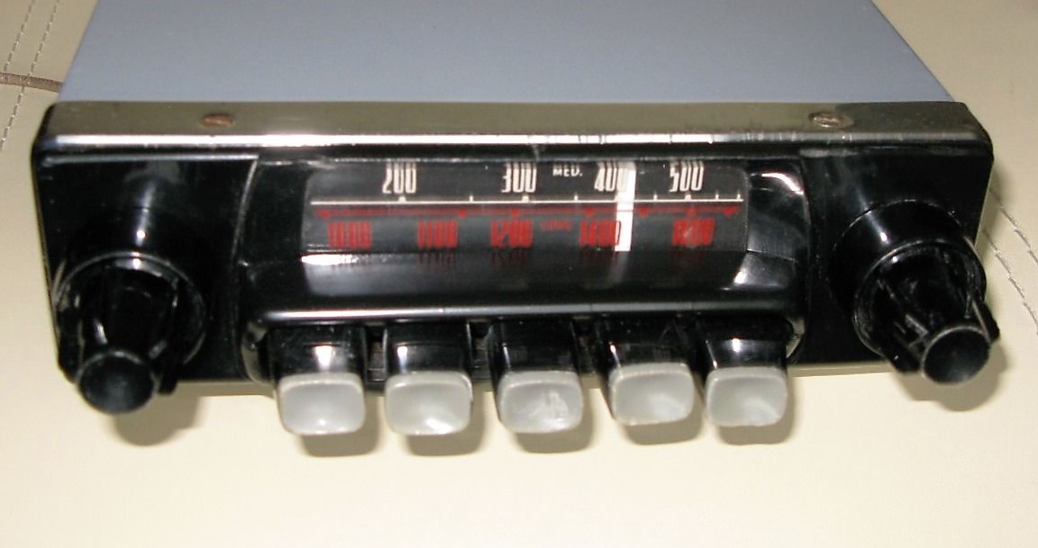
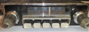
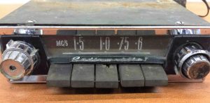
3.8 Model 202X with Medium wave only (1955-1957)
The Model 202X was a popular, simpler version of the 200X with Medium Wave reception only, which was especially sold in the USA. The photos below show versions with cream fronts on the (black) push-buttons which was (as stated before) the case for the majority of factory-installed Jaguar XK 140 radios. All 5 buttons now acted as pre-sets for MW stations.
In line with the above, there also was a Model 202R version to be combined with the more powerfull RB amplifier unit. The Jaguar part number for this receiver was C.11792.
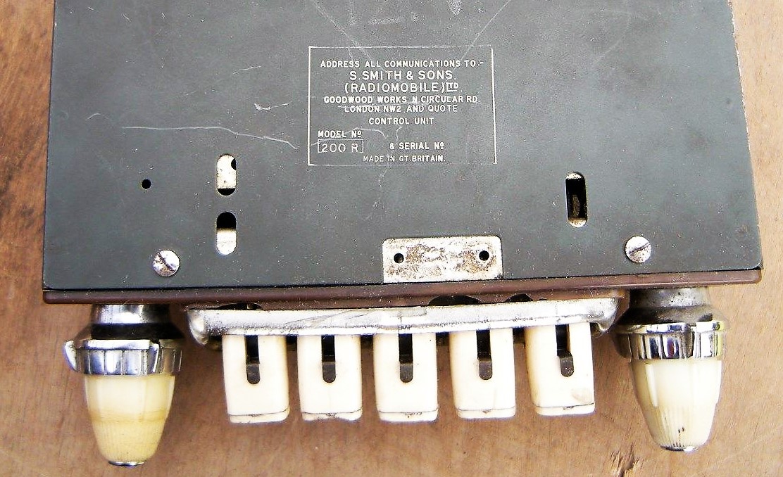
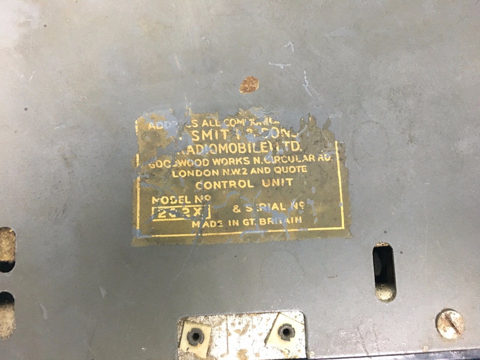 Note that versions for the USA were still Emitron branded/printed for the earlier described reasons. See photos above: note label showing model 202X made by Radiomobile.


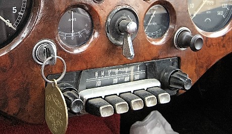
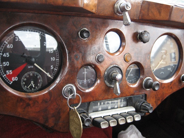
 Five examples of XK 140’s with Model 202X


 Model 202X in Mk VII
 Special version for Australia with specific stations per state on the scale. Black fronts of push buttons but missing cover (Photo: Roger Payne)

The photo above shows an original HMV (Radiomobile) radio fitted in a late 1954 DHC sold new in Australia. Note the HMV logo on the centre push button. Radiomobile provided special scales per state (or combinations thereof) in Australia to indicate local stations.
 Operating Instructions 200 series radios incl. Emitron in USA.
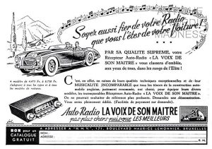 Also sold on the Continent: 1955 Belgian ad

3.9 Other 200 series radios
The 200 series was an extensive range with many different models. Again, although not “Optional Extras”, some of these versions may have ended up in a Jaguar XK via dealers especially in the former “Commonwealth” countries. A short survey:
- Model 201X 6 or 12 Volts switchable version of Model 200X.
- Model 203X 6 or 12 Volts switchable version of Model 202X.
- Model 212X 6 or 12 Volts switchable version of Model 200X with adjustable polarity.
- Model 213X 6 or 12 Volts switchable version of Model 202X with adjustable polarity.
- Model 220X 12 Volts only, identical to Model 200X but economy model without push-buttons
- Model 221X 6 or 12 Volts, identical to Model 200X but economy model without push-buttons
Note that each of the above models required a particular Amplifier corresponding with the features of the radio: voltage, polarity and output power. E.g. the Model 220X (a type mentioned by Radiomobile as being correct for the XK 140; see also 3.13) was supplied with amplifier XE and Model 221X with amplifier XF. See paragraph 3.10.
3.10 Amplifier Units for the 200 series
A new amplifier type had been introduced for the 200 series. In order to avoid that later amplifiers could be connected to earlier radios (and vice versa) the new generation had a 5-pin plug instead of the old 8-pin plug system. In addition the loudspeaker cable now had a 3-pin plug instead of the 4-pin system of the previous generation. The “X” range had two versions with a different power output. The new “R” range had an adjustable polarity switch and consisted of 4 types (only 12 Volts versions listed here).
The Radiomobile code for all amplifier units was Model 92450, but followed by the amplifier type e.g. /XB or /RB. Note that Jaguar recommended the more powerfull “B” units only: either 92450/XB or 92450/RB.
For the 200 series Jaguar used only the 92450/XB version with part number C.11796.
- XA 12 V; two valve standard amplifier for 1 speaker; positive to earth; maximum output 2W
- XB 12 V; three valve “De Luxe” amplifier for 2 speakers ; positive to earth; maximum output 5W
- XC 6 or 12 V switch; maximum output 2W
- XD 6 or 12 V switch; maximum output 5W
- XE 12 V; adjustable polarity; maximum output 2W
- XF 6 or 12 V switch; adjustable polarity; maximum output 5W
- RA 12 V; adjustable polarity; 2 valve; maximum output 2W
- RB 12 V; adjustable polarity; 3 valve; maximum output 5W
- RC 6 or 12 V switch; adjustable polarity; 2 valve; maximum output 2W
- RD 6 or 12 V switch; adjustable polarity; 3 valve; maximum output 5W
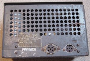
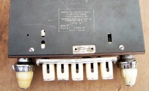
 New (round) 5-pin connector type plugs on XB and RB power units. Speaker plug has 3 pins.


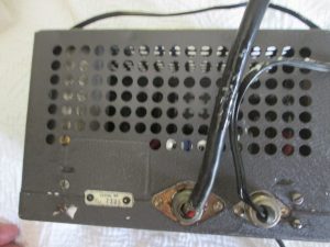
 Detail of 5-pin connector plug.

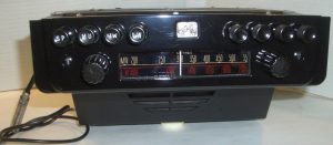
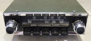
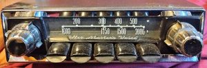
3.11 Model 230R with Medium and Short wave (1955 – 1960)
The Model 230R was a version that “survived” a number of Radiomobile radio generations as it was used for more than 5 years, offered both in the Jaguar XK 140 and XK 150. The model was still of the “3-unit construction” with a separate Amplifier of the RB type. It had a receiver for MW plus 8 SW bands: 90m, 60m, 49m, 41m, 31m, 25m, 19m, and 16m therefore suitable for a number of non-European and non-NA countries. Jaguar describes this version as the RMH 230R/VB, the suffixes indicating the execution of dial and knobs. Note that the 200X and 202X version had suffixes /VP or even /VP.26. Other Jaguar models apparently had different knobs and/or dials: as an example, the Mk2 version had RMH 230R/BCU. The exact meaning of these suffix codes are not known (yet).
 Model 230R was Radiomobile branded, not HMV

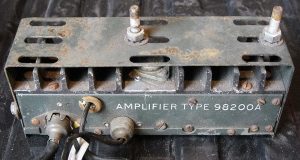
3.12 Amplifier Units for the 230 series
The RM 230R was supplied required the more powerful RB amplifier with code 92450/RB. This range of amplifiers consisted of an RA type with single output and the aforementioned RB version suitable for two speakers. See information in 3.10. Jaguar only used the 92450/RB version with part number C.11687.
3.13 Installation of the 200 and 230 series in XK 140’s
The original “Smith Radiomobile installation instruction for 200X, 202X, and 220X for the Jaguar XK 140” describes the radio installation which is in principal the same for OTS, DHC and FHC.
In case of XK 140 DHC and FHC models, the receiver is installed in place of the “drawer” in the instrument panel using special brackets replacing those to which the drawer slides have been mounted. For the OTS model the receiver is mounted with special brackets beneath the dashboard.
Jaguar had mounted a special steel bracket under the parcel shelf for the Amplifier (or Power Unit) during production, whereby the OTS and the FHC models shared the same bracket with Jaguar part number BD.9541: “Plate and Bracket assembly for mounting of Radio Power Pack“. The DHC had a different Jaguar part number for the bracket: BD.8926 “Plate inside Luggage Compartment for mounting of Radio Power Pack when required”.

 Jaguar part number BD.9541 : “Plate and Bracket assembly for mounting of Radio Power Pack” in a XK 140 FHC.
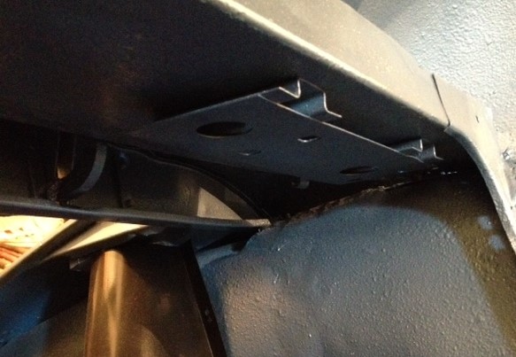
The bracket provided by Radiomobile for the amplifier unit was fixed under the Parcel Shelf on the left side in front of the Petrol Filler. All XK 140’s had such a factory built mounting plate, no matter whether a radio had been ordered or not. The XK150 had a similar mounting plate at the left side of the boot (instead of the top).
Radiomobile used two different codes for the Amplifier Bracket: RMH 93508 and RMO 3451. The latter has Jaguar part number C.11797.
 Amplifier installation method for DHC & FHC models
 Later Bracket RMH 93508 has two slots.

The loudspeaker is mounted in a pre-cut hole in the millboard that covers the footwell vent on the right side. This hole has an oval shape roughly 3” by 8” for the standard Radiomobile speaker. The left side had no pre-cut hole.
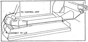 Cable routing XK 140 (and 150)
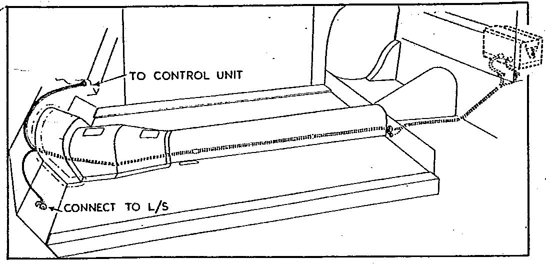
The cable with the two 5-pin connectors runs from the receiver to the amplifier (length 120”or 305 cm) and a second cable with one 3-pin connector (length 168” or 427 cm) runs from the amplifier unit to the loudspeaker in the front.
3.14 Typical price levels of 4260 and 4300 series radio systems
The Jaguar 1955 UK price list for the XK 140 shows retail prices around £33 for Model 4262 in the FHC up to over £45 for Model 4300 in the DHC (these prices include fitting, aerial and tax). The total UK price (October 1955) for an XK 140 varied between £1600 and £1860, the latter for the XK 140 FHC in Special Equipment (MC) form, which means the cost of a radio was between 2 and 2.5% of the car.
In the USA prices for the (standard) XK 140 versions had meanwhile been lowered and was now at a level of $3460 (OTS) to $3800 (DHC/FHC) with an additional $450 to pay for the MC version. No 1955 prices are known for the optional radios but we may assume that prices remained at the 1953 level of $115 to $164 or around 3.5% of the total car price.
4. Radio installations offered for the XK150
4.1 Available “optional extras”
It is well known that most Jaguar Spare Parts Catalogue (SPC’s) are not up to date as to the applied parts in production. The XK 150 Spare Parts Catalogue (J.29/1 1960/1966) is no exception and lists the following (1955 introduced) radios available as “Optional Extras”.
- Model 200 X with Long and Medium wave
- Model 202 X with Medium wave only
- Model 230 with Medium and Short wave reception
These radios have already been listed for the XK 140 in the previous chapter and described there in detail.
We first must take a closer look at the way Radiomobile structured their product portfolio. Before 1955 the programme was in composed of high end and low end versions within each new series of radios. From 1955/1956 onwards the portfolio was much more structured having two distinct levels:
- a “low end” Radiomobile branded “single unit” radio combining receiver and amplifier.
- a “high end” His Master’s Voice branded “3-unit” radio (receiver, amplifier and speaker).
Over the period 1955 till 1961 the Radiomobile “low end” single units have been coded 20, 40 and 50 series, whereas the “high end” His Master’s Voice radios were coded 200, 400 and 500 series. It looks like the US delivered “high end” radios gradually were all Radiomobile branded while in Europe the His Master’s Voice brand was continued. After 1961 the “high end/low end” policy continued for some years but the branding became Radiomobile only (starting with the 600-series launched in 1962). The “low end” series remained initially based on the design of the 200 series, without the push-buttons however. The design of the “high end” series moved towards a “De Luxe” version with the His Master’s Voice name prominently shown above the push-buttons.
The Radiomobile Installation Instructions for the XK 150 DHC & FHC of June 1957 mention Model 20X and Model 22X radios in addition to the 200 series. Other available Radiomobile versions have hardly been mentioned in Jaguar literature. However, all below mentioned radios may have been used in the XK 150 and therefore each version will be described hereafter.
For completeness, the Radiomobile Installation Instructions for the Mk VII, Mk VIII and Mk IX of January 1959 mention Model 40T, 41T, 42T, 400T, 401T and 402T as the available options. We may assume that the Mk VII has been mentioned in these instructions for retrofitting these radio types in existing cars, as production of the Mk VII had been stopped in 1956.
- 20 series
- Model 20X with Long and Medium wave
- Model 22X with Medium wave only
- 400 series
- Model 400T Long & Medium Wave
- Model 401T Long & Medium Wave; polarity switch
- Model 402T Medium Wave only; polarity switch
- 40 series
- Model 40T Long & Medium Wave
- Model 41T Long & Medium Wave; polarity switch
- Model 42T Medium Wave only; polarity switch
- Model 42TC Medium Wave; polarity switch; tone control
- 500 series
- Model 500T Long & Medium Wave
- Model 501T Long & Medium Wave; polarity switch
- Model 502T Medium Wave only; polarity switch
- Model 530T Medium & Short Wave; polarity switch
- 50 series
- Model 50T Long & Medium Wave
- Model 51T Long & Medium Wave; polarity switch
- Model 52T Medium Wave only; polarity switch
- Model 52TC Medium Wave only; polarity switch; tone control
4.2 Radiomobile 20 series (1956 – 1958)
The “20 series”, introduced June 1956, marks the beginning of the era of miniaturization, having a compact “single unit” construction. Although it still contains (3) valves it lacks a separate amplifier unit of the previous generations. For the first time this Radiomobile model had a Selenium Rectifier replacing the vacuum tubes that had been used sofar.
 Model 20X in black (left) and with cream knobs (right)

Model 20X is a MW and LW receiver suitable for both “plus” and “minus” to ground. This was the period in which all car manufacturers gradually changed over from positive ground to negative ground and this new model was suitable for both.
As the photo above clearly shows, the 20 series is closely related to the 200 series: the same front lay-out and knobs have been used, however without the push-buttons, necessitating the introduction of a new injection moulded front. The Radiomobile brand name is prominently shown below the scale, which had been started with Model 230. The HMV name or logo is no longer used on these “low end” models. Again variations in colour and shape of knobs were available from the factory.
Model 22X is identical to the 20X version, apart from the fact that this is a MW only radio. Note that there was also a Model 30X which was however a “short-wave converter” to be used in combination with any radio to facilitate SW reception using 8 bands.
Radiomobile also offered Model 30X series, but this was merely a SW converter to be connected to a non-SW radio.
 Model 30X was a SW converter

4.3 His Master’s Voice 400 series (1958 – 1960)
The new 400 series replaced the 200 series by the end of 1958 and still had the “3 unit construction”. Whereas the receiver unit had 5 valves, the amplifier was now fully “transistorised”, replacing the radio valves of the past. As stated before, the His Master’s Voice name is prominently shown on these “high end” versions. The new 400 series consisted of three models: Models 400T, 401T and 402T.
- Model 400T had LW and MW reception with 5 preset push-buttons and had positive earth.
- Model 401T was in fact identical to the 400T version, but had a polarity switch.
 Model 400T

Model 402T also had the polarity switch of the 401T model but was Medium Wave only. Note that on the photo below of a Model 402T, the scale is only showing MC/S (or MHz) values for US customers. Metres are normally used in Europe as we can see on the Model 400T photo above. Note that the 402T shows the Radiomobile brand instead of His Master’s Voice. It looks like the US delivered radios now were all branded Radiomobile while the European (including UK) delivered versions were still His Master’s Voice. The question remains what had happended to the Emitron brand in the late Fifties?
 Radiomobile Model 402T. Here shown in a 1961 XK 150. No His Masters Voice for US customers! Photo: rmsothebys.com


Note that some XK 140’s have been observed fitted with the Model 402X; this must be a later installation.
4.4 Radiomobile 40 series (1958 – 1960)
The 40 series (introduced late 1958 or early 1959) was the successor of the 20 series. Whereas the 20 series had a “X” suffix the 40 series had a “T” suffix for “Transistor”. The 40 series was almost identical to the 20 series but had 4 valves (instead of 3) and an amplifier with a single “power transistor” having a maximum output of 1.75 W, all packed within a single unit. The speakers should have an impedance of 3 Ohms or 1.75 Ohms, depending on the contacts chosen in the (3 pin) speaker connector.
 Model 40T with MW and LW
 Model 42T with MW only
Model 40T had LW and MW reception; no push-buttons. It was delivered suitable for positive earth. Model 41T was identical but had reversable polarity. Model 42T (photo above) also had the reversable polarity but this was a MW only radio. Finally there was the identical Model 42TC which had “Tone Control” in addition.

Underside of 40 series; note Polarity Plug Socket (RH top corner)
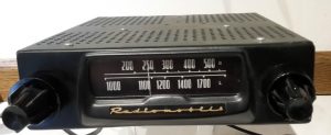
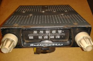
4.5 His Master’s Voice 500 series (mid 1959 – mid 1961)
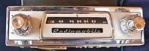
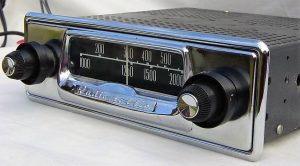
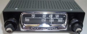
Introduced around 1960, the 500T series was the successor of the 400T series. The amplifier units remained identical for the two series. The 500 series also offered four models: Model 500T, 501T, 502T and 530T. The 500 series had “oval” instead of “square” push buttons. It was replaced by the 600T series in September 1961.
This model is listed in the Mk IX Spare Parts Catalogue, but we know it was also available for the XK150 in the 1960’s. Only the RMH.500TB and the RMH.502TB have been listed by Jaguar with Jaguar part numbers 8265 and 8264 resp. Note that the B behind the T suffix of the receiver refers to the amplifier type that is used in combination with this receiver: here the RMH.98200B with Jaguar part number 8267. See more info in 4.7. Note that the 500 series was also used in very early E-types, succeeded by the 600 series from mid 1961.
 Model 500T with black knobs and “oval shaped” push-buttons

 Model 501T is identical to 500T but has polarity switch (not yet required for Jaguars of this period)

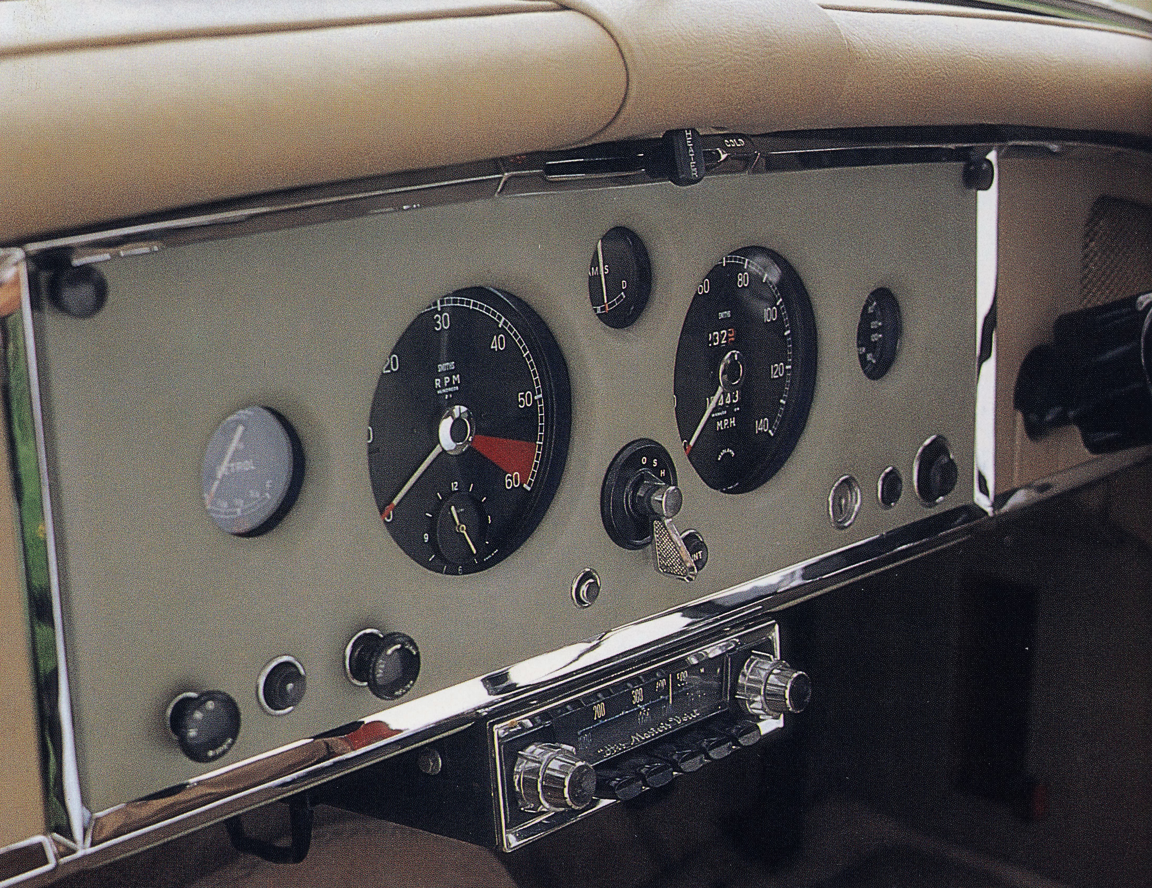
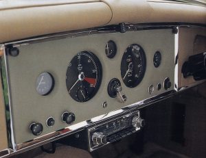 Model 500T in XK 150. Note the speaker grille mounted in the dashboard above the steering wheel Photo: Duncan Wherret, Jaguar XK 120/140/150
Model 500T (positive earth polarity only), was nearly identical to its predecessor Model 400T. In line with the 400 series portfolio, Model 501T was identical to Model 500T but had a polarity switch, whereas Model 502T had MW only (and a polarity switch).
 Operating instructions for 500T and 600T. Latter shows various available models as per 500T series.
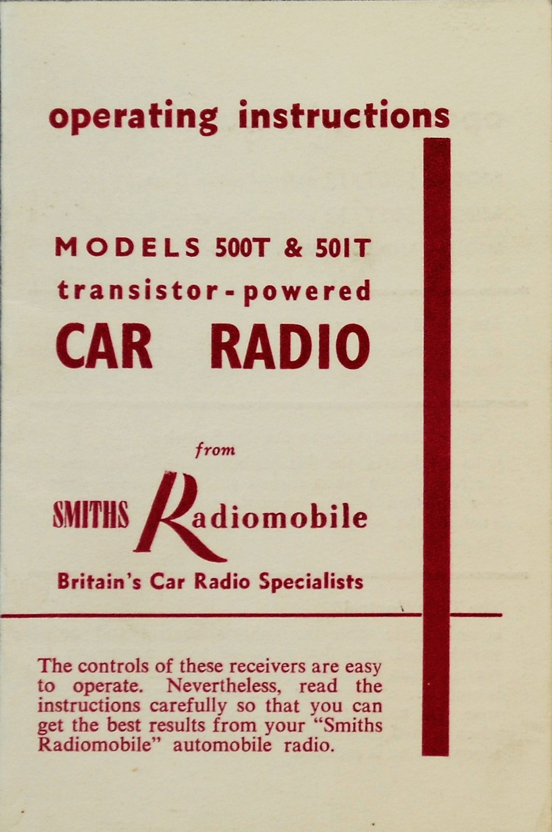
Note: 600T is “Radiomobile” and no longer HMV. Photo Roger Payne
The 1961 Jaguar Mark X SPC lists yet another 500 series model: Model 530T. This is a Medium & Short Wave radio that has been coded similarly as Model 230 of the older 200 series. Although we only see one dial the whole inner scale rotates when the wavelength knob is turned. The following scales are shown: MW, 90M, 60M, 49M, 41M, 31M, 25M, 19M, and 16M. Unlike the other 500 series models the 530T model has no push buttons and is also in that respect a successor of Model 230.
Jaguar lists this version as 530TB/VA with part number C.22931 and C.24489. This model is also used on “S” series and various E-types of the Series 1.
 Model 530T with MW & SW

4.6 Radiomobile 50 series (1960 – 1962)
The 40 series was rather short lived as the 50 series replaced the (introduced late 1958) 40 series in 1960. Same model programme as for the 40 series with respectively Model 50T, 51T, 52T and 52TC. The 50 series had 4 valves and 2 transistors, just like the 40 series.
Model 50T is a MW and LW receiver without polarity switch (positive earth only). Note the RH turn knob for band choice with L and M. Model 51T is identical to the 50T however had a polarity switch.
Model 52T and 52TC are identical to the 51T but have Medium Wave only; Model 52TC has in addition “Tone Control”. Note that the scale of Model 52T is in MC/S (or MHz) as we have seen on Model 402T.
 Model 50T
 Model 51T with polarity switch
4.7 Amplifier units for the 400 and 500 series.
Two Amplifier units are used: the A or B Type with 1 respectively 2 transistors. Jaguar opted for the B type amplifier with code 98200B both for the 400 and 500 series with Jaguar part number 8267.
There was also a 98200K amplifier which had an additional heat sink, probably for tropical applications.
Various brackets exist for installing these Amplifiers. The bracket below has Radiomobile code RMO 3320K. Note the large transistor(s) and aluminium cooling fins.
 98200A; not recommended by Jaguar
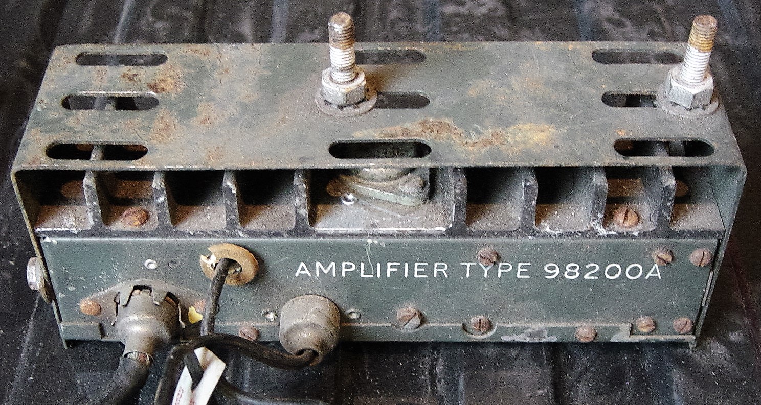
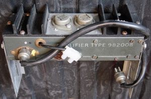 98200B as used by Jaguar

4.8 Installation of the 200, 400 and 500 series as well as 20, 40 and 50 series in the XK 150
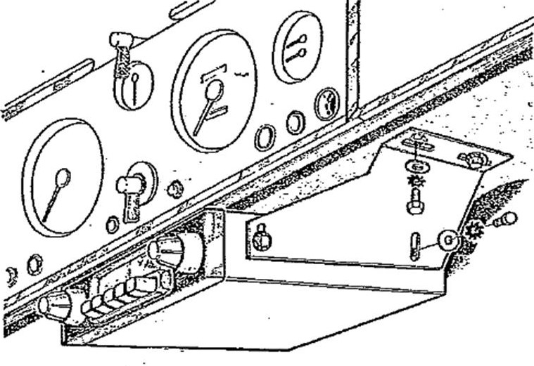
Note that the installation of the above models in the XK 150 is identical to the method described for the 200 series in the XK 140, but only using the special mounting brackets of the XK 140 OTS as the XK 150 has no wooden instrument panel. In case of Automatic versions (with the selector handle under the dashboard), extra long brackets were used to lower the receiver installation (see photos below).

 Special brackets for RM 20, 200, 202 and 230 in XK 150 Loudspeaker fitting in XK 150 dashboard

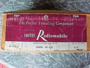
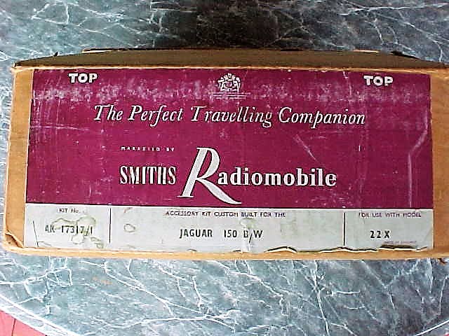
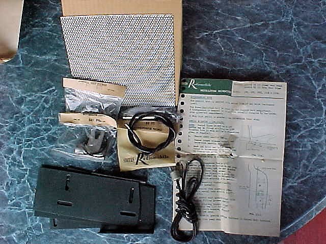
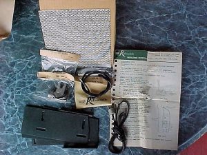 Original Smiths Radiomobile accessory kit for installation of Model 22X in XK 150 with Automatic (BW)
4.5 Typical price levels of the 20 series radio systems
The XK 150 FHC sold for around £ 1950 in the UK by Spring 1958 (in standard form), while an Optional radio was listed from £35 upwards. We notice in general that radio prices dropped as a percentage of the total cost of the car below 2%. This trend continues after the introduction of the new XK 150S when we relate the cost of optional radios to a selling price £2065 in 1958.
US selling prices for the XK 150 and XK 150 S had increased by 1958 to a level of $4550 and $5150 (respectively) for standard versions. Radio price levels (apparently) had dropped to a level around the $ 100 mark meaning the cost of an optional radio had come down to around 2% of the car price. This may also have been influenced by the introduction of “transistor” radios, gradually replacing the valve type of radio.
5. Observations and conclusions
The period 1948 to 1961 was an interesting one as we witnessed the change-over from the “vacuum radio tube” technology towards the new “semi-conductor” era. This is not only reflected in miniaturization of equipment, but also by a steady increasing performance with respect to quality of reception and sound, as well as output power for the loudspeakers.
The first Radiomobile products, starting 1946, were “individual developments” lacking an overall product portfolio approach, which is not surprising for a newly established company. These first Model 100 radios (but also the 4000 and 4200 series) received continuously new updates and derivatives were added “as the need arose”. Within this range, new low-end versions were created by simply offering less features. This also included adaptions to geographical differences, like offering “MW only” versions (e.g. no LW for USA).
By 1955 Radiomobile management introduced a new comprehensive product portfolio concept with typically two ranges: a low-end and a high-end range having each a different “platform”. This portfolio was consistently further developed into the Sixties, whereby the logic of product codes remained the same, contributing to a better and immediate market acceptance of new versions when introduced.
It is interesting to see how Radiomobile dealt with the situation regarding the “His Master’s Voice” rights in North (and South) America. The company’s initial intention was to use the HMV name and logo throughout their portfolio, which became also clear from various magazine and newspaper advertisements using the slogan: “The new HMV Car radio by Radiomobile”. However, due to the existing RCA rights in North and South America, the policy using the HMV brand and logo had to be abanded in the USA: their most important export market! The Emitron brand, chosen as a substitute, did not have the same market impact and also lead to “double branding” for most of their products.
Via an intermediate period of having HMV branding for the high-end range and Radiomobile for the low-end versions (with exception for the USA where around 1955/1956 Emitron had been replaced by Radiomobile for high-end radios as well), the company finally felt strong enough to completely omit the HMV brand in favour of using Radiomobile for all versions all over the world.
Lucas High Frequency Horn HF1748 on Jaguars: 1953 to 1961
“Loud and Clear”
Lucas High Frequency Horn HF1748 on Jaguars: 1953 to 1961
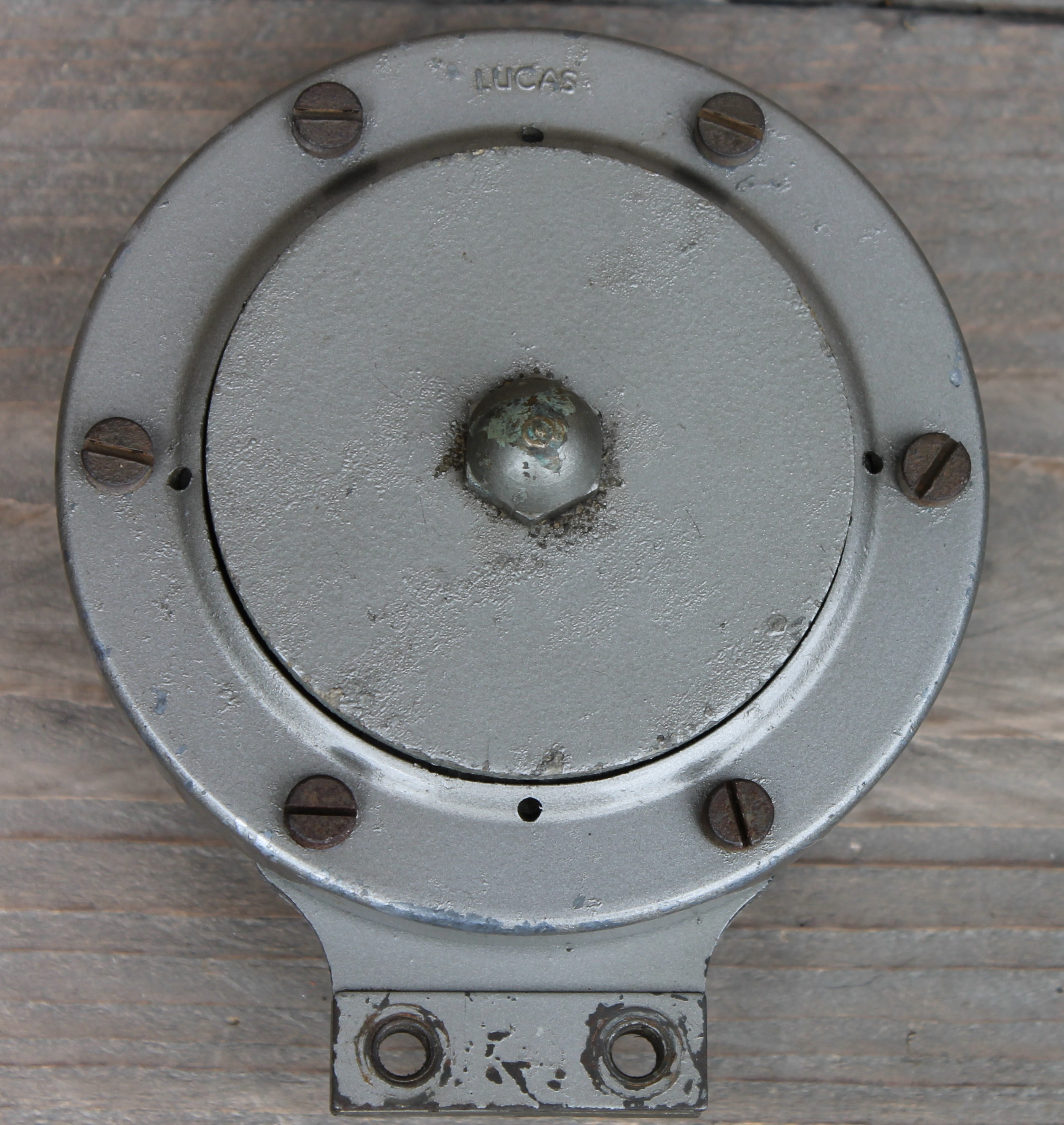
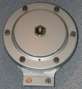
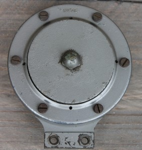 Original unrestored Lucas HF1748
Lucas High Frequency (HF) horns: short history
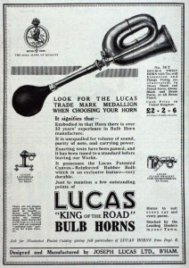
In the 19th century Joseph Lucas was a well-known British manufacturer of bicycle parts and accessories (including bicycle bells) that started manufacturing car horns in an early phase of the “new era of motorized transportation”. In about 1890 Lucas introduced a “horn with rubber ball” which in fact was an air horn.
 1923 Lucas advertisement 1926 advertisement with Lucas’ first electrical horn

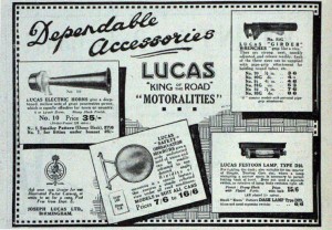
The first electrical horn made by Lucas was introduced around 1925. From 1930 onwards they manufactured also so-called “High Frequency” (HF) horns: several versions in different sizes became available during the Thirties and Forties. Some became very popular like the Alto and Altette, and both have been extensively applied on both motorcycles and cars.
 1920’s Lucas brass car horn 1931 Lucas advertisement first generation HF horns

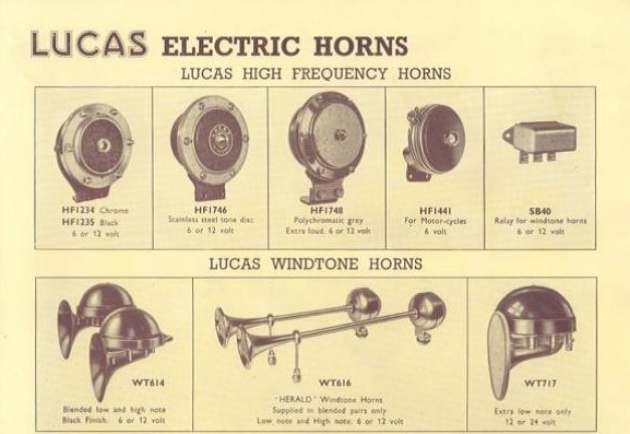
After the war a number of the older types were continued until in 1950/1951 Lucas launched a complete new generation of HF horns consisting of three ranges: HF1746, HF1747 and HF1748. The latter became the most popular version by far and has been used by Jaguar over many years. The HF1748 will be further discussed in this article.
1953 Lucas “Overseas Service Catalogue” shows both HF1746 as HF1748 version but not HF1747
Information on the introduction of the HF1748:
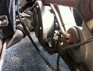
The very first car to have the new HF1748 horn is most likely the Jaguar XK120C (or “C-Type”) in spring 1951. The three Jaguar “Works” Le Mans cars (XKC 001/002/003), the development of which started late 1950 and manufactured and tested early 1951, had one single (low note) HF1748 horn painted black (wrinkle finish), and not grey as with all later Jaguars with this type of horn. This was mounted near the fuse box at the RHS of the scuttle.
“Works” Jaguar (probably XKC 002) with first Lucas HF1748 horn in black
The very first production car with the new HF1748 horn (also with low note and in black wrinkle finish) is most probably the Bentley Mark VI (4½ liter) manufactured and supplied in the autumn of 1951 for export markets. This horn had Lucas part number 70067A and we may assume that this is the same horn as used by Jaguar on the XK 120C Works cars.
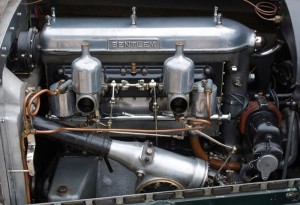 Bentley with HF1748

Jaguar used the HF1748 in production from 1952 until about 1961. Interesting to see that a so-called “Wind Tone” horn (Lucas type WT29U) was the predecessor of the HF1748 in Jaguar’s production and that another “Wind Tone” horn (Lucas type WT618) succeeded the HF1748 from about 1960. It remains unclear why Lucas ceased production of the HF1748 in 1961. Only special (military) versions were continued and years later in 1966 another production run for service reasons.
Principle of HF horns
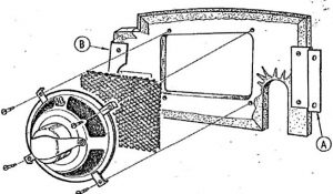
Electrical horns consist of a steel diaphragm attached to an iron armature; this assembly is placed in a magnetic field generated by a copper coil wounded around an iron core.
Steel diaphragm complete with iron armature (note original color)
The current through the coil generates a magnetic field that attracts the armature + diaphragm against the core. At the moment the armature hits the core, contact points are opened and the magnetic field collapses. This causes the points to close again after which the cycle starts all over. Thus the diaphragm starts to vibrate (about 300 to 400 x per second) causing sound waves that we can hear. Normally electrical horns have a sound level of more than 100 db.
There are two basic types of Lucas horns:
“Wind Tone” horns amplify sound waves using a “trumpet” of specific length, related to the wave length of the sound. These “trumpets” can be both straight or “spiraled” in order to keep the horn compact in size. Lucas examples are the aforementioned types WT29(U) and the later WT618.
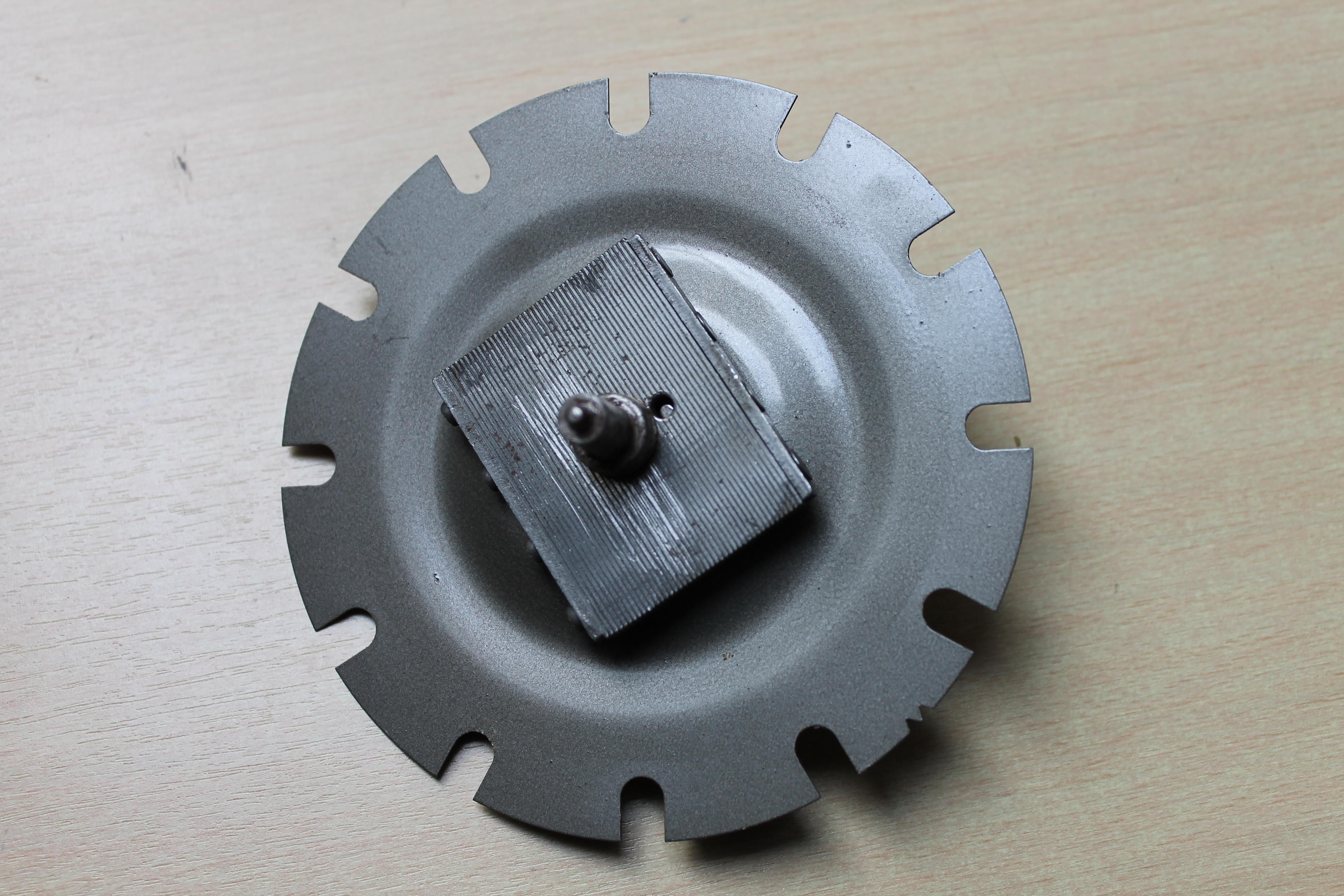
“High Frequency” horns are based on a different principle: every time the armature (+ diaphragm) hits the core, a special “Tone Disc” (firmly attached to the diaphragm and having a specific calculated “natural frequency”) gets into a “higher harmonic” resonance.
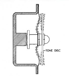
 Principle of a High Frequency horn Special “Tone Disc” at the front of a HF 1748 horn
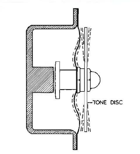

Lucas HF1748 horns can be obtained as either “High Note” or “Low Note” version. It is in fact the construction of the diaphragm that determines whether we’ll have a high or low note, and not the tone disc which is the same for both versions. The results is a sound of 300 to 400 Hz, combined with the higher harmonics of these frequencies , leading to a penetrating yet pleasant sound. As mentioned, the material choice and construction of the Tone Disc are crucial, as is the fixation of the Tone Disc to the diaphragm. Lucas used a specific aluminum alloy for the Tone Disc.
Because the powerful sound of the HF horn is generated by using an additional resonance of the Tone Disc, it will be clear that other vibrations in this construction have to be prevented as they may affect the resonance. It is therefore of the greatest importance that the HF horn is firmly attached to a “solid” part of the car.
Survey of Jaguars with Lucas HF 1748 horn
1. Jaguar XK 120C (or C-type)
As mentioned in the introduction, the application of HF1748 horns started with the Jaguar XK 120C (or C-type) in 1951. These first horns were black (as later applied by Bentley and Rolls-Royce). The photo in the British magazine Autocar of July 13, 1951 clearly shows a black HF1748 mounted on the scuttle of a “Works” XK120C. This is further supported by a photo at page 132 of the book “Jaguar Sports Racing & Works Competition Cars to 1953” by Andrew White. A year later another British magazine “Motor” in their “Road Test” of October 22, 1952 shows a HF 1748 on a later XK120C (the so-called “Production” models) which now have a grey color as will be the case for all later Jaguars.
 Recent photo of the 1952 C type XKC 045 with single HF1748 at the RH side (note the SU H8 carburetors!)
 Recent photo of Jaguar XKC 053 with single HF 1748 (moved to LH due to installation of “cold air box” for triple Webers)

2. Jaguar XK 120
Although never mentioned in the XK 120 Jaguar Spare Parts Catalogue, according Lucas catalogue 400D of 1954 and 400E of 1960, the Jaguar XK 120 did have two Lucas HF1748 horns (Low Note and High Note) in 1953 and 1954, however only on DHC and FHC versions manufactured for export. See also the remarks made for the Mark VII here below.
3. Jaguar Mark VII and VII M
According Lucas catalogue 400E of 1960, but also mentioned in Jaguar Service Bulletin Nº 129 of August 1953, the Jaguar Mark VII had two HF1748 horns from chassis number 716017 (RHD) and 736522 (LHD) manufactured from 1953 onwards. These Lucas horns had part number 70063B fort the low note version and 70071B for the high note. According the Lucas catalogue the application of these horns was initially limited to Export versions of the Mark VII during 1953 and 1954. Thereafter all Mark VII versions had these horns until 1958.
Jaguar part numbers C.5226 and C.5227 have been mentioned fort the first time in the above Service Bulletin. This early part number may indicate that the Lucas HF1748 had become part of the Jaguar part stock in 1952 or 1953.
The thesis that HF1748 horns have also been applied by Jaguar on the XK120 from 1953 onwards is further supported by the fact that the horn relay (as used for the WT29U Wind Tone claxon) is only mentioned during the period 1951 till 1953 and no longer thereafter. The HF1748 (in 12 Volts execution) does not require a horn relay as the maximum current is only 4 Amps whereas Wind Tone versions have a maximum of 6 to 7 Ampère. A complete set of Wind Tone horns may draw up to almost 15 Amps and Lucas even prescribed the use of a 50 Amp fuse in the supply of the horns.
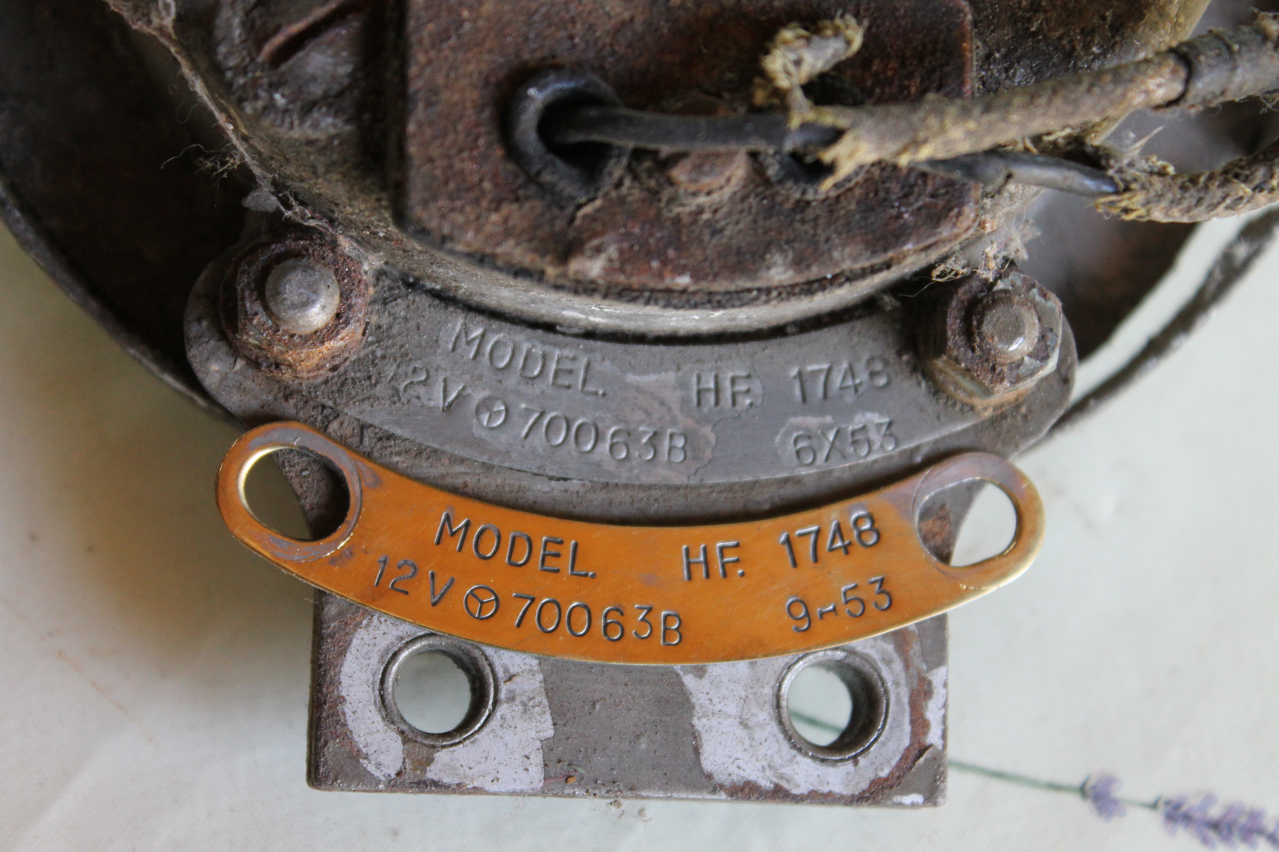
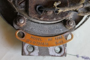 Correct HF1748 brass type plates from 1953 for Mark VII or XK 120; note the non-uniform way of date code stamping!
4. Jaguar XK “D-type”
There is no hard written data available from either Jaguar nor Lucas, whether the D-type actually had the HF1748 as standard equipment, but there is sufficient “physical” evidence that they had a single Lucas High Frequency horn. This is further supported by the fact that the XK-SS of 1956 (using the remaining unsold D-type cars) actually had one single HF1748 High Note horn (see paragraph 7).
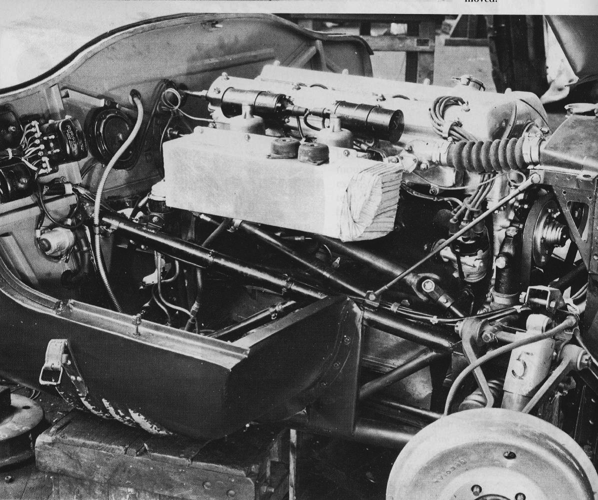
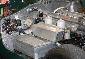
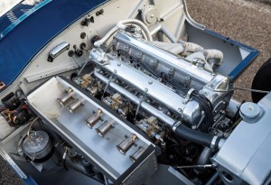
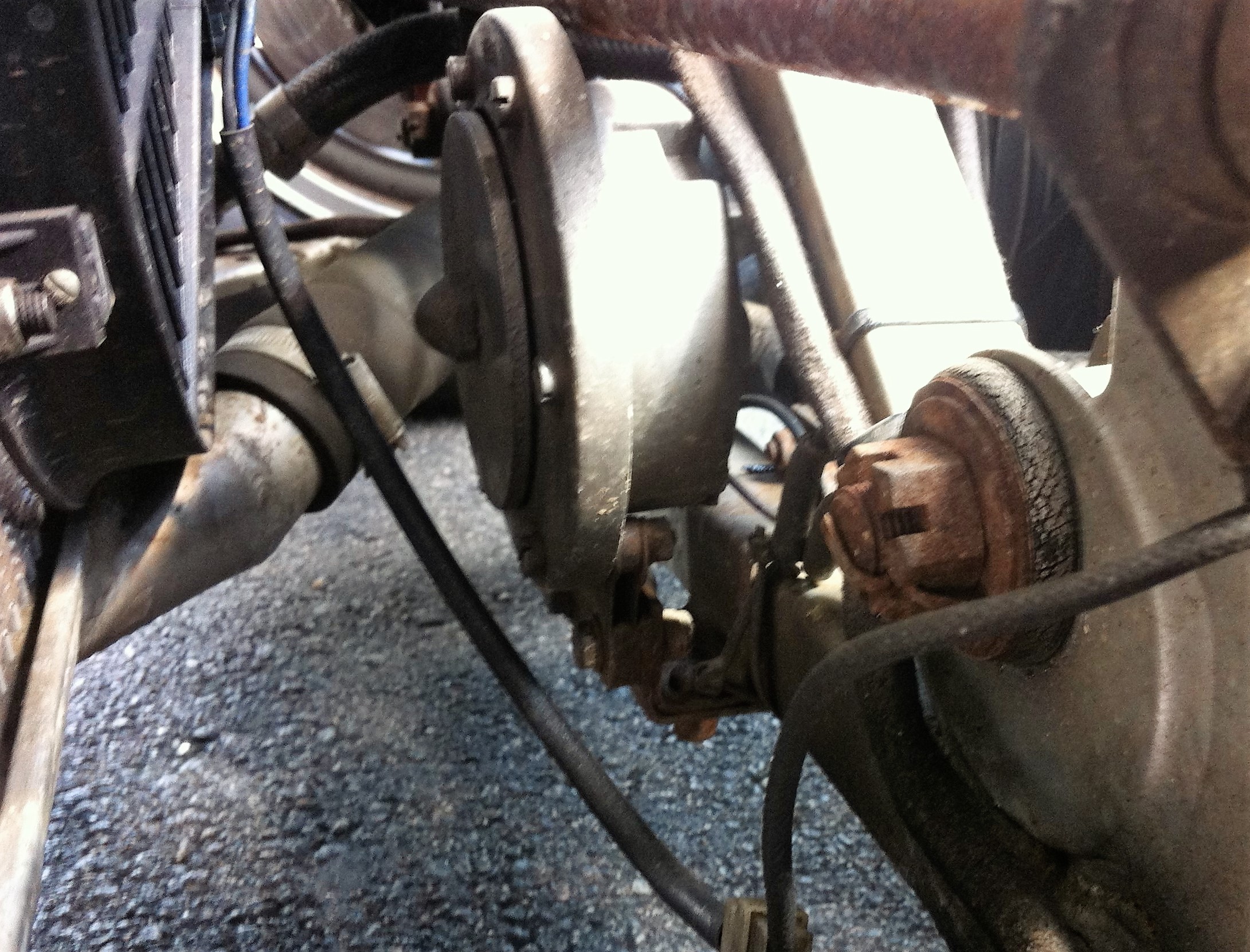
 HF1748 behind the radiator on a D-type
5. Jaguar XK 140
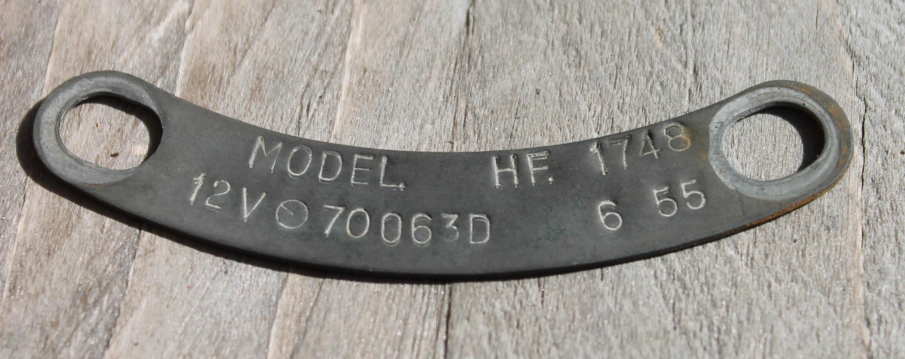
From the introduction in 1954 the Jaguar XK 140 had HF 1748 HF horns until the end of production in 1957. Jaguar had already assigned part numbers C.5226 and C.5227 for (resp.) the High Note and Low Note version. The Lucas numbers now had a different suffix: 700071D and 70063D (resp.).
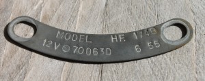 Original Lucas type plate for XK 140 or later Mark VII
6. Jaguar XK 150
The Jaguar XK 150 continued the use of the HF1748; the XK 150 Spare Parts Catalogue simply copied the part numbers of the XK140, although Lucas had meanwhile changed the suffix in 1956 from D to E and in 1958 again from E to F. This information for owners who absolutely need the correct part numbers for their cars!
7. Jaguar XK-SS
The open 2-seater on basis of the D-Type Jaguar had in 1957 (just like the C-Type some years before) one single but now High Note HF1748 horn with Lucas number 70071/E.
8. Jaguar Mark 1 and 2
Also the Jaguar Mark 1 (both 2.4 and 3.4) had the Lucas HF1748 from production-start. The part numbers over the period 1955 to 1959 are identical to those from the XK140 and XK150 as described above.
The Jaguar Mark 2 (all engines: 2.4 , 3.4 and 3.8) had from October 1959 till September 1960 the HF 1748 as standard version.
9. Jaguar Mark VIII and IX
As successors to the Mark VII (M) models, the Jaguar Mark VIII and IX continued the use of the Lucas HF 1748 from 1957 to 1960 with Lucas numbers 70063E or F and 70071E or F until production ceased early 1961.
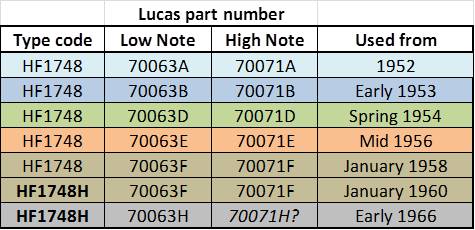
Lucas HF1748 part numbers and date codes
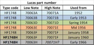
It is interesting to look at the part number sequence as assigned by the Lucas development group in 1951 to the various versions of the HF1748 and their respective introduction dates. We may conclude from this list that part numbers have apparently been “reserved” for applications that started only some years later. A survey of Lucas part numbers:
- 70062 6 Volt Low note Grey Unknown (motorcycles)
- 70063 12 Volt Low note Grey 1953
- 70064 24 Volt Low note Grey Unknown (lorries/trucks)
- 70067 12 Volt Low note Black 1951
- 70070 12 Volt High note Black 1952
- 70071 12 Volt High note Grey 1953
- 70073 24 Volt Low note Green 1952 (military)
- 70079 6 Volt High Note Grey Unknown (motorcycles)
The 1954 Lucas catalogue van 1954 lists the part numbers for the different HF1748 horns produced in black and grey. Jaguar only used the “polychromatic” grey version which had initially Lucas number 70063 for the low note and 70071 for the high note version. Although the Lucas 1954 catalogue does not provide any suffix letter, we know that in 1953 the suffix B and in 1954 the letter D was used. Apparently suffix C is not used by Lucas.
In addition there is also the Lucas number 069448 for the 70063 low note horn. This particular part number was already used for the 1954 Austin A30. Jaguar kept on using the Lucas numbers 70063/D and 70071/D in their catalogues up to 1961 although Lucas had meanwhile officially changed the part number for supplies to Jaguar in resp. 069448 and 069474. We have to assume that 0694xx numbers have been assigned to “assemblies” that consist of the original part plus a number of additional items required for (e.g.) installation. These 0694xx numbers have been used by Lucas for other horns as well from 1953/1954 onwards.
The black version of the HF 1748 with Lucas part numbers 70067 and 70070 for the low note and high note version, however, has always kept these numbers as there are no examples of 0694xx numbers for these horns.
If you would like to use the correct Lucas HF1748 type plate (or tag) for your car, the survey below might help you. Note that the Lucas type indication HF 1748 was changed (for reasons unknown) in 1960 to HF 1748H.
 Survey of part numbers over the years
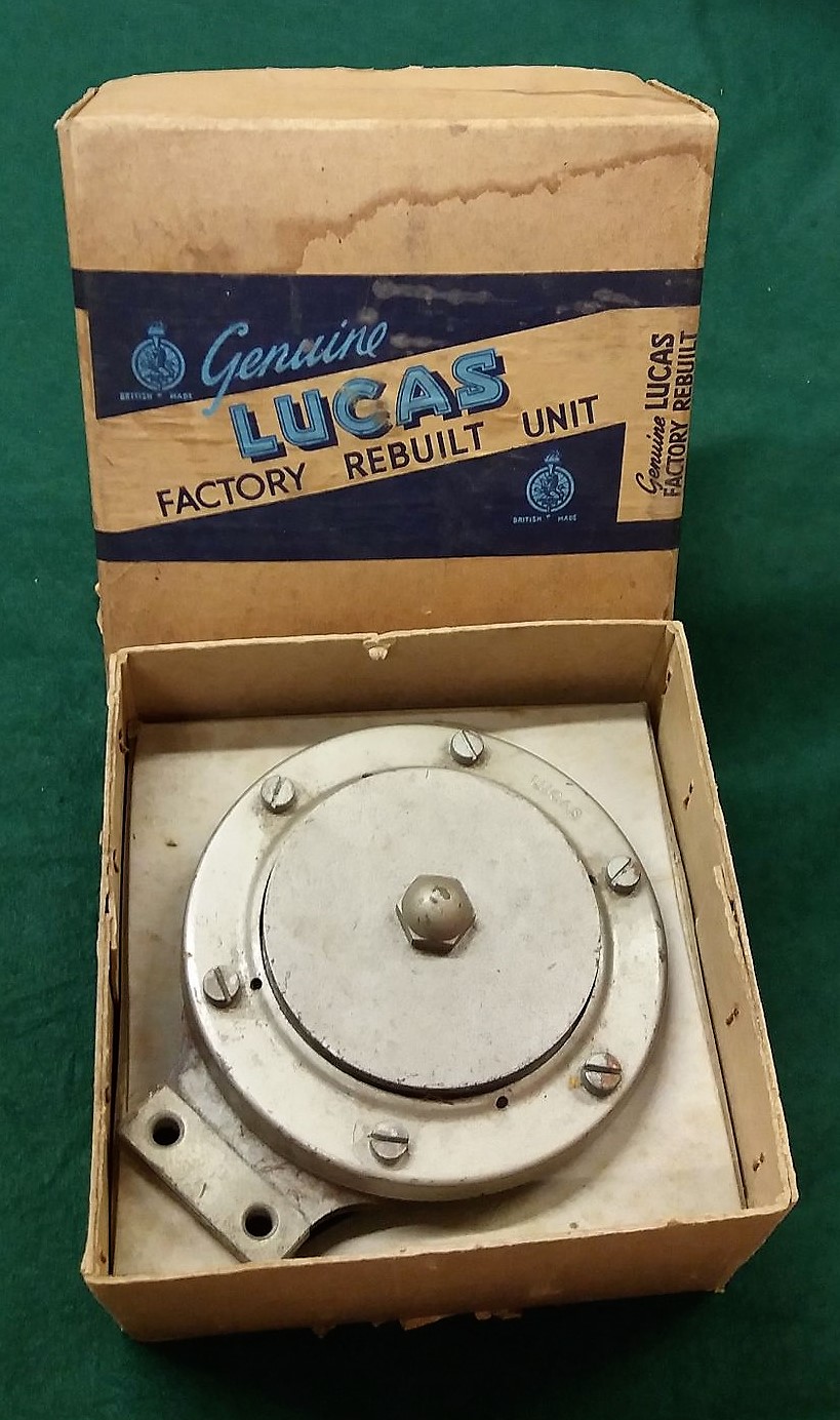
After production ceased Lucas provided Factory Rebuilt Units that received an H date code. An example manufactured in March 1965 is shown below.
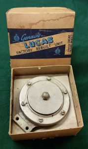
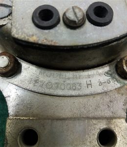 Factory Rebuikt Units

Lucas 1748 horns in detail
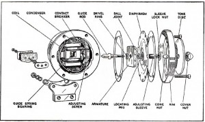 Exploded view of HF1748
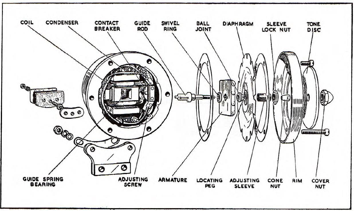
The “exploded view” above shows the construction of the HF1748. The mechanical differences between the high and low note version only relate to the steel diaphragm: Lucas part number 703726 for the low note and 703727 for the high note version. It is therefore absolutely possible to change a low note into a high note horn just by changing the diaphragm.
Repairing/restoring a Lucas HF1748 horn
If a HF1748 does not function well any more (or not at all), it is in most cases possible to repair or restore but this will depend on the overall condition of the horn. Just turning the adjuster screw at the back will not cure the problem, unfortunately!
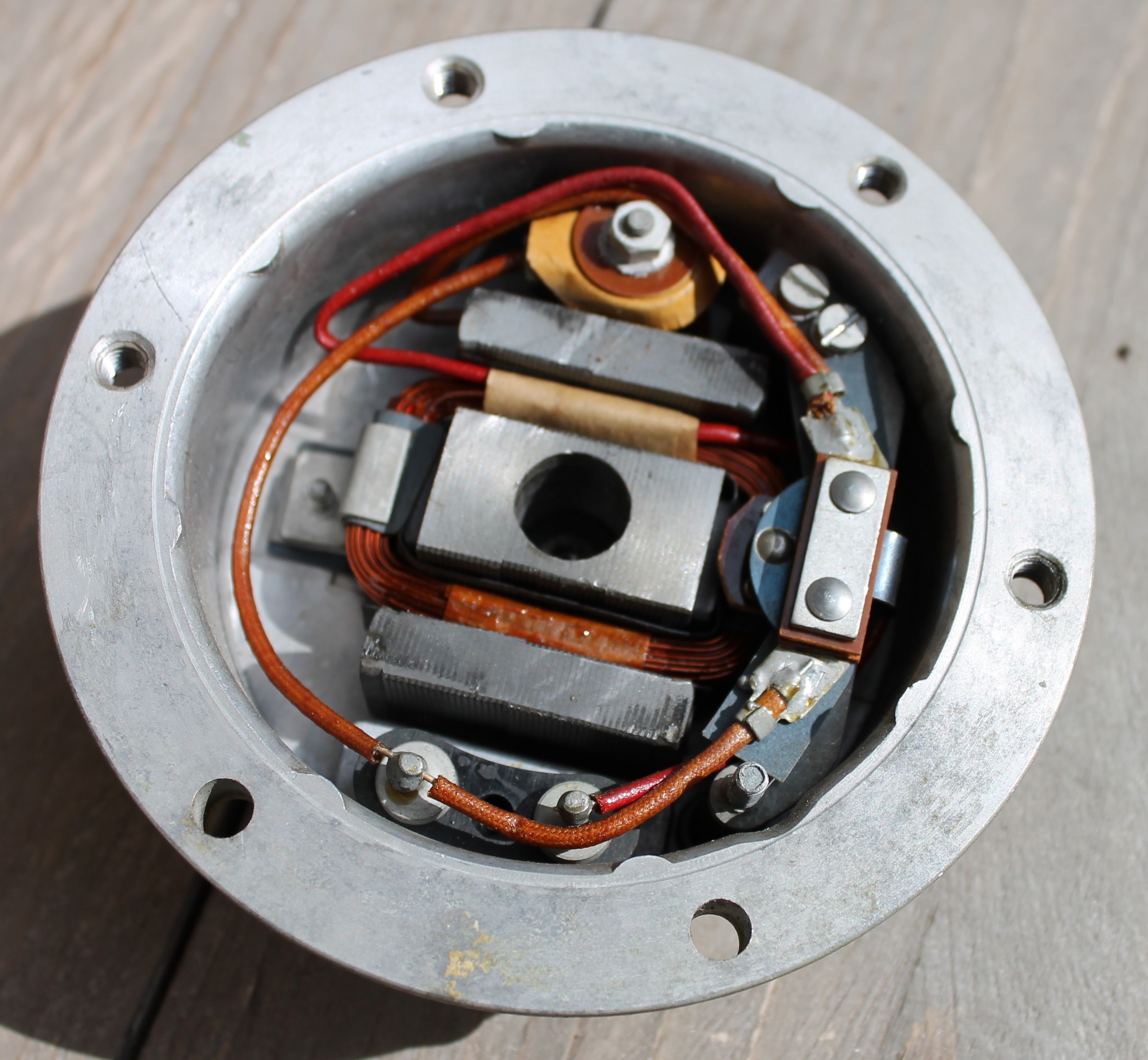
 The inside of a 60 year old HF1748 can look like this!
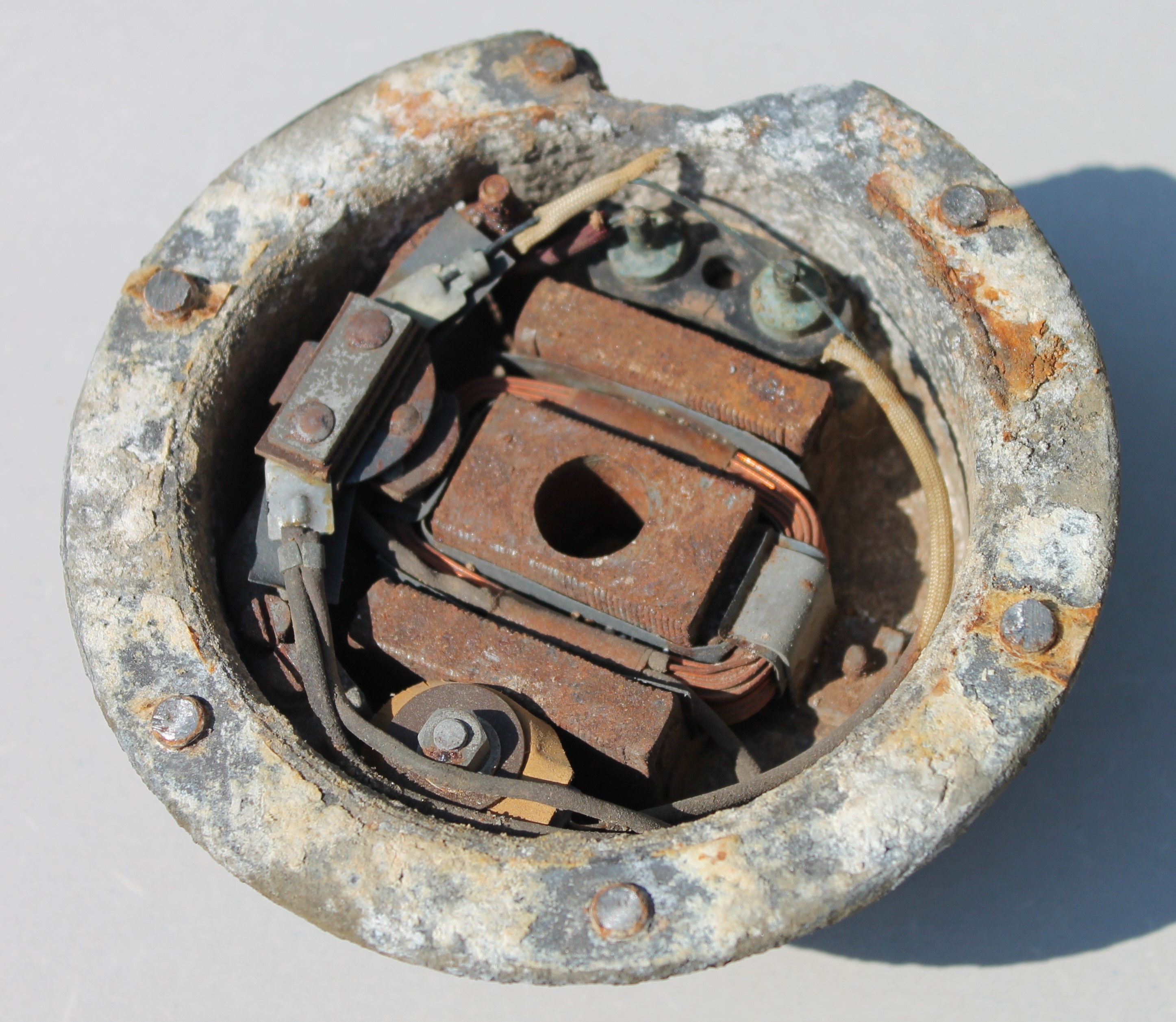
 But also like this: corroded beyond repair!
There are 60 year old examples that look still immaculate inside, but there are also cases where it looks as if the horn has been submersed in seawater for decades and are corroded to a degree that nothing can be saved! The aluminum outer rim is particularly fragile and might show cracks or has been completely disintegrated; welding of this zinc-aluminum alloy is (almost) impossible.
Lucas stopped the supply of service parts for these HF horns many decades ago. There are some specialist companies that may have some parts while others have remanufactured small batches of the most “popular” parts like e.g. the outer rim, the tone disc and the paper gaskets. The mounting bracket (Jaguar 3502, Lucas 704651) can still be ordered from most Jaguar part suppliers. Note that there is also an almost identical Bracket 690617 as used for the Lucas Wind Tone horns type WT29(U) and WT618, but the dimensions are different and it will not fit the HF1748.

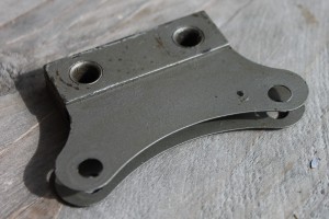 Original Bracket for HF1748; still available
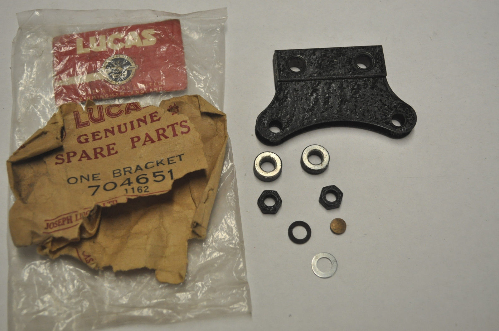
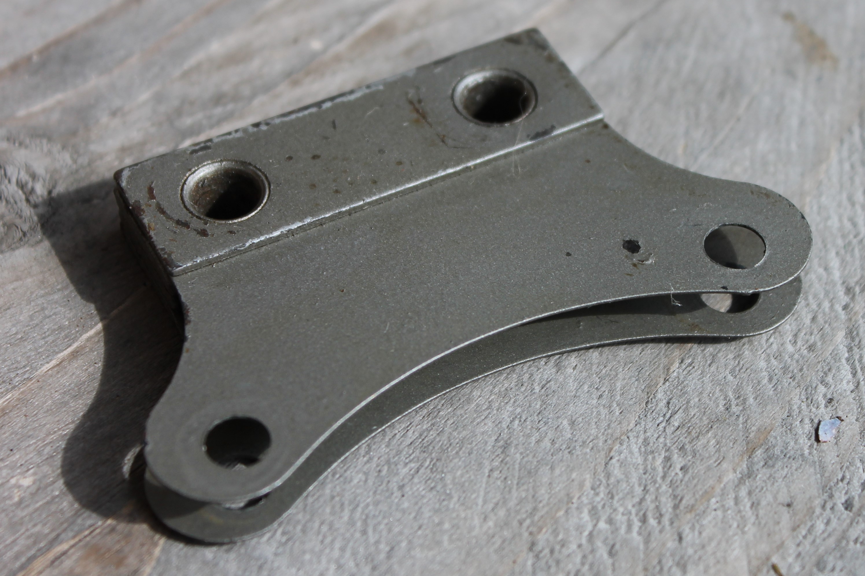
In most cases parts have to be reused and missing parts have to be taken from another horn or made new. The outside of all Jaguar HF1748 horns have been painted grey. This color (Lucas reference: “polychromatic grey”) however changed somewhat over the years (darker/ lighter). The term polychromatic is used for the first generations of “metallic” paint however with different and far less metal flakes than is used today. The original Lucas versions have been completely painted in grey, meaning also screws and brass parts are grey. Some owners like the looks of polished brass parts: the cover nut and type plate are shining “like new”, but remember that Lucas delivered them only covered with grey paint. The diaphragm is sometimes painted grey and sometimes black, but I’ve even seen grey painted over black.
Reproduction outer rim, now made from a stronger aluminum alloy!
Adjustment of HF1748 horns
After a complete restoration, a number of settings require adjustments. This assumes some “craftsmanship” and specific tools and measuring equipment. The procedure in short:
All parts should be checked for defects and repaired where required, before they can be re-used (or not..). The contact breaker points have to be cleaned in a similar manner as with your ignition points. Check the continuity of the various electrical components and circuits with a suitable “multi meter”. The capacitor (condenser) can also be defective after 60 years or may have developed an earth leak. Note that later production (1966) had a “modern” capacitor (15 µF ± 10% 500V DC) which can now be used for replacement and is available from any good electronics specialist.

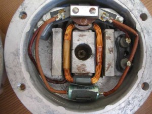 Later type of capacitor
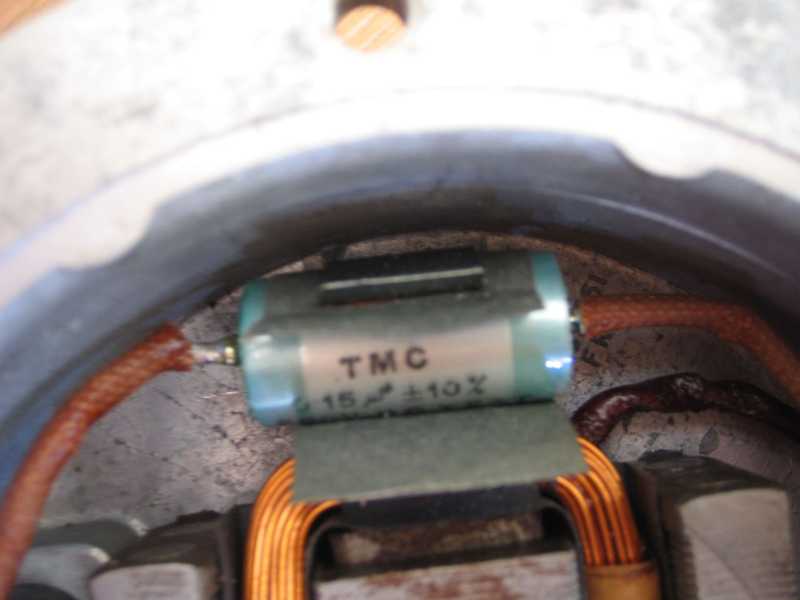

A logical consequence of the difference in “stiffness” of the low and high note diaphragm is that the maximum amplitude of the two diaphragms have to be set differently, in order to obtain the maximum resonance of the tone disc. The maximum amplitude of the vibration is determined by the air gap between the armature and coil core. The Low Note version requires an air gap of about 0.025” (or 0.6 mm) and the High Note has a shorter distance of about 0.020” (or 0.5 mm); both values for 12 V versions only.
To adjust the air gap, the “Adjusting Sleeve” (see Exploded View) should be turned in or out until the correct value has been obtained. To do so, first screw the Adjusting Screw at the back of the horn a number of turns in clockwise direction in order to fully close the contact points: the armature will now rest on the core if the circuit is connected to 12 V. Use a clock dial to measure the distance in the center of the diaphragm. Don’t continue the power to the horn for too long as the coil may become (too) hot. When the correct air gap has been obtained , the contact breaker has to be adjusted with the Adjusting Screw at the back until a loud tone is heard. The same screw is used for setting the maximum current which should be about 4 Amps max. Now your horn should function “Loud and Clear”.
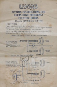 Fitting instructions leaflet for HF1748

Other related Lucas HF horns
There are two versions that have to be mentioned here:
I. The first is a special military version of the Lucas HF1748 as used by Daimler on their Ferret Scout. This military armored reconnaissance vehicle used by the British Army was produced from 1952 till 1971. It was a 24 Volts HF1748 horn in a green color. The Lucas part number is 70073 (+ suffix) but the type plate also mentions the Daimler code FV.157950. Apart from the (24 V) coil and color this horn is identical to the HF1748 as described above.

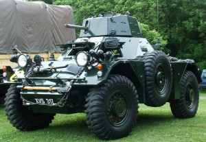 Military version HF1748 Daimler Ferret Scout Note special
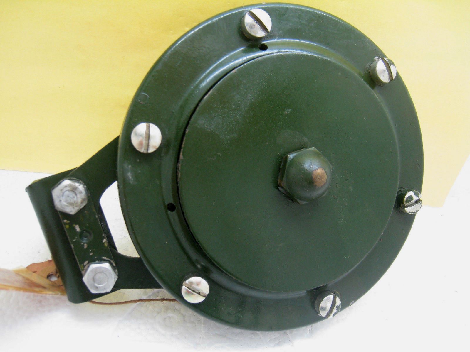

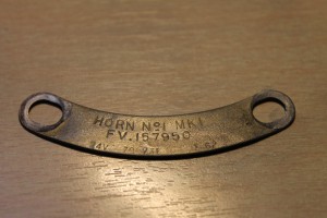 Special Daimler type plate for Military version
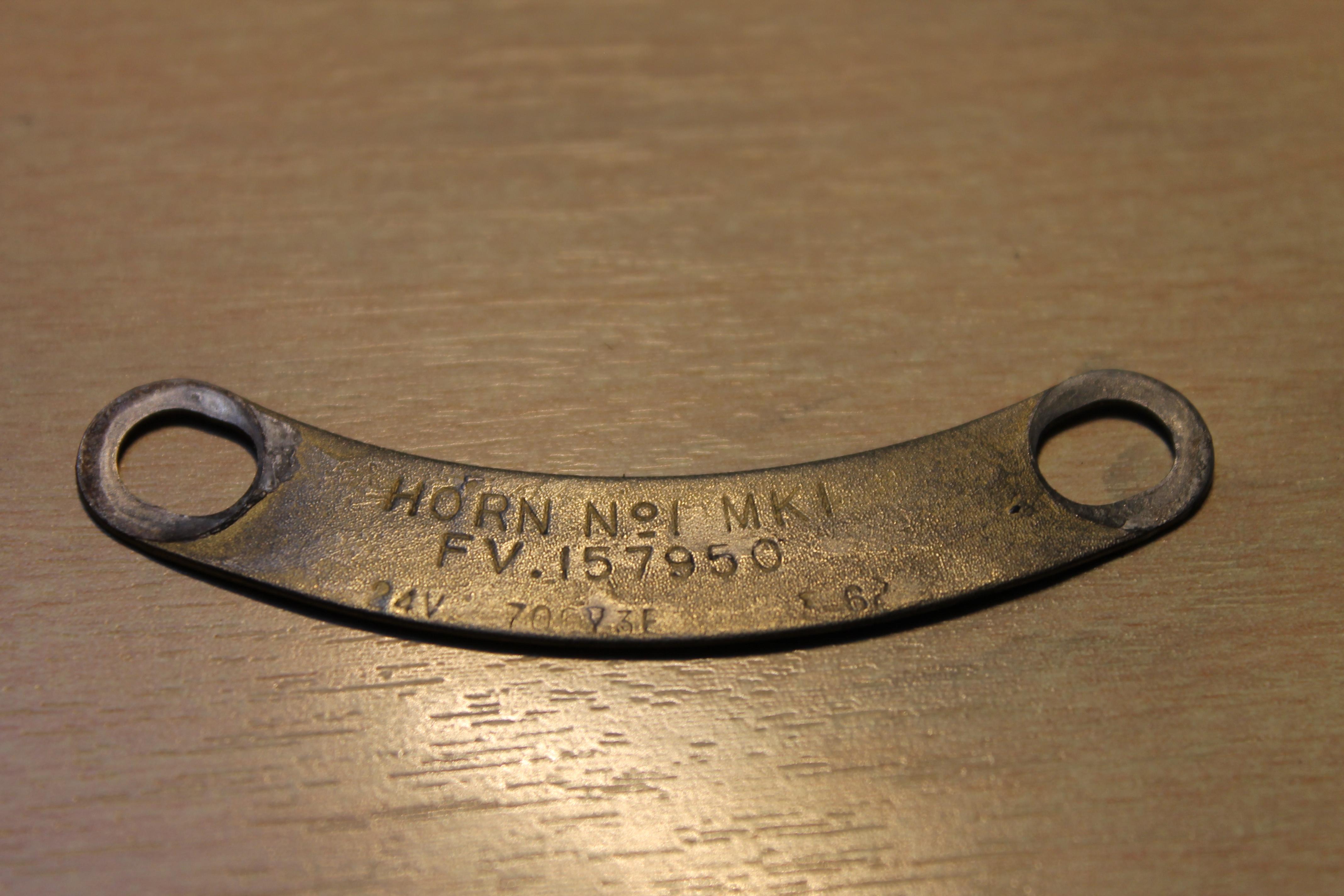
II. The HF1746 is a “weather resistant” version of the HF1748 specially made for “exposed” installation e.g. at the front of a lorry or motorcycle: some parts have been made of stainless steel or have been chromed.
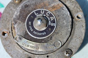
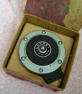 Lucas HF1746 requiring a full restoration Original Lucas HF1746 in box

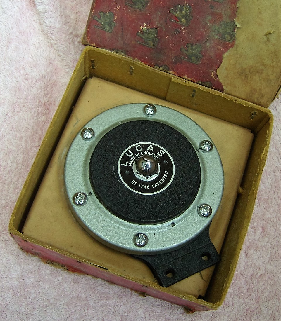
Other British cars with Lucas HF 1748 horn(s)
- Aston Martin DB3/S (1956) with Lucas 70063/D and 70071/D.
- Austin A30 (1954) with single Lucas 70063/D.
- Austin A40 and A50 “Cambridge” (1955) with 70063/D and 70071/D.
- Austin Healey “100”, “100M”, “100 Six” and “3000” from 1954 to 1960 with 70063 and 70071.
- Bentley Saloons (1951 to 1955) had Lucas 70067 and 70070 in black.
- Cooper “Monaco” Sports (1959 to 1960) with single 70063/F.
- Rolls-Royce “Silver Dawn” and “Silver Wraith” (1953 to 1959) with 70067 and 70070 in black.
Pre-EEC national homologation of vehicle lighting
Approval marks for (continental) Europe
In 1976 the new European Regulation76/761/EEC on “motor-vehicle headlamps which function as main-beam and/or dipped-beam headlamps and to incandescent electric filament lamps for such headlamps” became mandatory for all EEC member states. This replaced the various national regulations in action so far. A survey of known earlier national regulations in Europe is found hereafter.
European countries (except GB) required a headlamp that fulfilled certain legal requirements regarding a “sharp cut-off” dipped beam in combination with a high light output.
France
The French Ministerial Decree of 8th October 1929 formulated a new regulation for car lighting, becoming effective per 1st May 1930. According this decree all cars shall have lighting equipment that should be able to:
- Light the road over 100 metres (indicated with the letter A)
- To suppress any blinding, without ceasing to light the road, when encountering other road users (indicate with the letter B)
All headlights developed to fulfil the above requirements will be investigated by a committee of the Ministry of Public Works (Travaux Public) to receive a conformity mark mentioning e.g. Agréé AB (Certified AB). All headlights mentioning Agréé AB are followed by the letters TP (Travaux Public) and the number of the certification of the homologation (№ 123) issued by the committee.
 Lucas lamp with French mark Agréé AB-TP No 457

Source: Optique des projecteurs d’automobiles; Editions de la Revue d’Optique théorique et instrumentale 1930.
Netherlands “The myth of the NL mark”
Per January 1st, 1954 a new law had been introduced in the Netherlands that all lighting (and bulbs) of all vehicles on the road should have a “state approval mark” in order to increase road safety. The requirements had been laid down in this law and testing requirements had been assigned to (and consequently drafted by) the Dutch electrical testing Institute KEMA. The “state approval mark” should be clearly visible on the relevant part. From that moment onwards all approved vehicle lighting (from bicycle rear-lamps to car headlamps) carried the NL mark.
All stories (often referred to in GB or USA) about NL meaning “not legal” or “near left” are incorrect: it merely was a type approval for the Dutch market required to sell cars in Holland.
KEMA was (and is) a leading European (ISO certified) laboratory in the area of electrical safety and the KEMA approval mark is still found today on many electrical products.
 Lucas 700 Continental 553940 with NL mark
Germany
According the „Straßenverkehrs-Zulassungs-Ordnung“ StVZO (Road Traffic Approval Regulation) lighting components on vehicles (generators, headlights, rear lights, reflectors) have to be made according an officially approved construction. The first Regulation dates from 13th November 1937. To show conformity, the German Transport Ministry (KBA) in Flensburg provides an approval mark on manufacturers request. It consists of a wave line with the letter K followed by the testing number.
Example: K 12345
The approval mark is placed on every approved light-technical element of the vehicle. The approval mark is obtained if components meet the applicable Technical Requirements (German: Technischen Anforderungen TA). This TA consisted of Annexes to § XXIIa of the German StVZO. Vehicle lighting without an approval mark shall not become commercially available nor sold; doing so is considered a felony.
Testing is not performed by the German KBA, but by the Licht Technical Institute of the Karlsruhe University, which is also shown in the letter „K” in the approval mark. The German KBA in turn checks the conformity to requirements, initiating regular tests of randomly obtained products from the production line.
 Bosch headlamp with K, NL and A approval mark
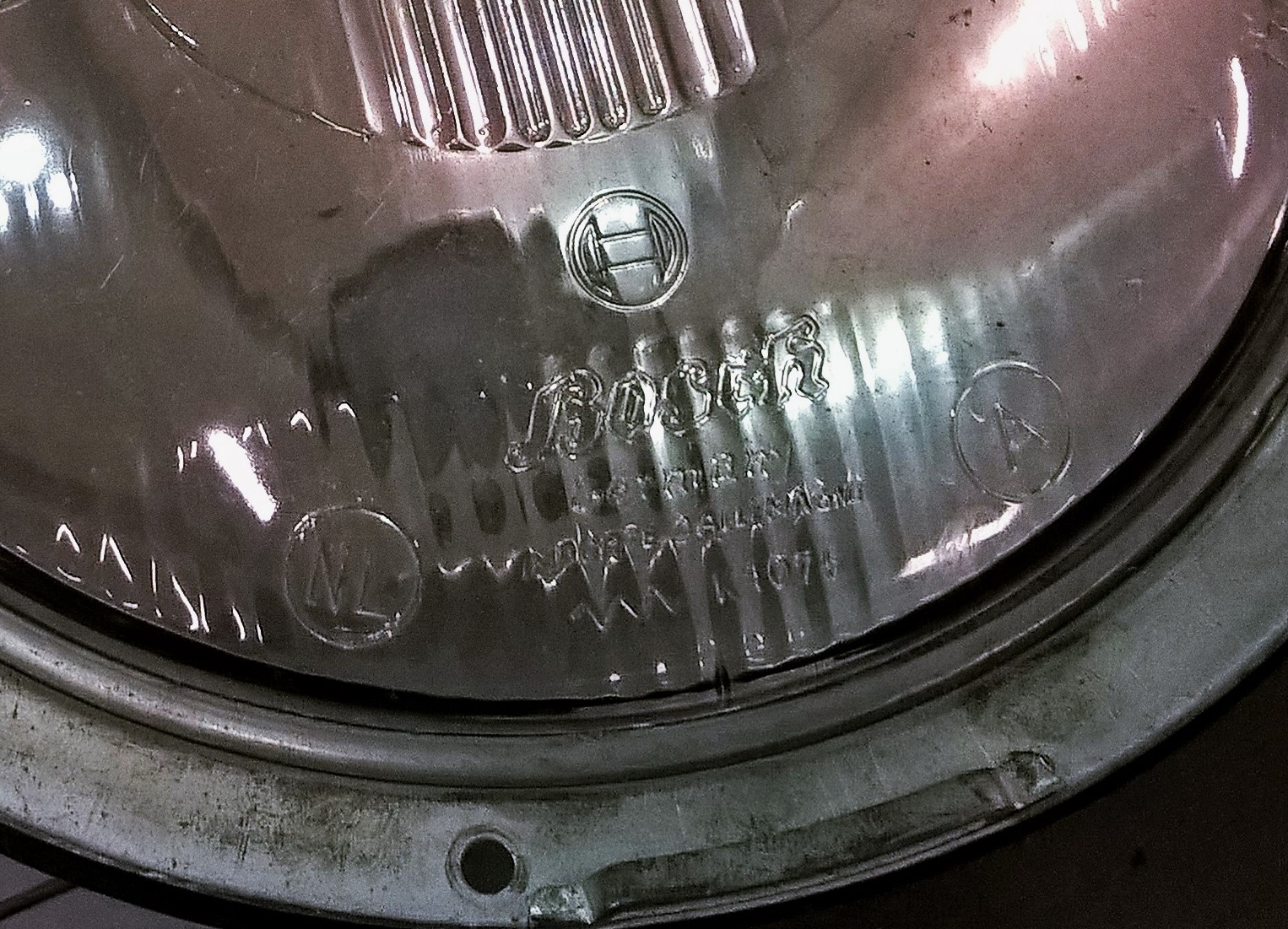
Today certain elements of this regulation is still applicable to Bicycles, whereas EEC/EU regulations have taken over other transport segments.
Conversion Trico switch PS-33A to PS-4A
Conversion Trico switch PS-33A (3 positions) to Trico PS-4A (2 positions)
Trico manufactured different switches for automotive applications. Although they look very similar, there is a distinct difference in their functionality.
The Trico PS-33A switch was used as a direction indicator switch with 3 positions: left, off and right. This switch was used by a number of British car manufacturers and can sometimes still be found in NOS condition.
Jaguar used the Trico PS-4A switch as an overdrive switch from 1955 till the early Sixties. It is a two-position switch (on/off) but in fact largely identical to the aforementioned PS-33A as the internals of the switch are common.
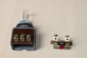 Trico PS-33A

The difference is that the warning light inside the switch has internal connections in case of the PS-4A, whereas the PS-33A has additional connectors on the bottom plate (which carries the warning light) but the correct internal connections for the warning light are missing. The way Trico made a two position switch from a three position is simply done by blocking the third position by using a rubber buffer that prevents the handle to move.
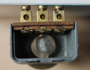
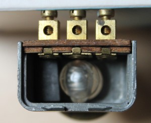 A rubber buffer is placed in the housing of the PS-33A to convert it to a 2-position switch


The PS-33A has only the letter B (for battery) positioned as an indication for the centre one of the three connectors on the phenolic back plate. It is easier to mark the other two contacts with E (for earth) and L (for “load” which in case of Jaguar is the solenoid of the overdrive).
 Marks for E and L in addition to the existing B
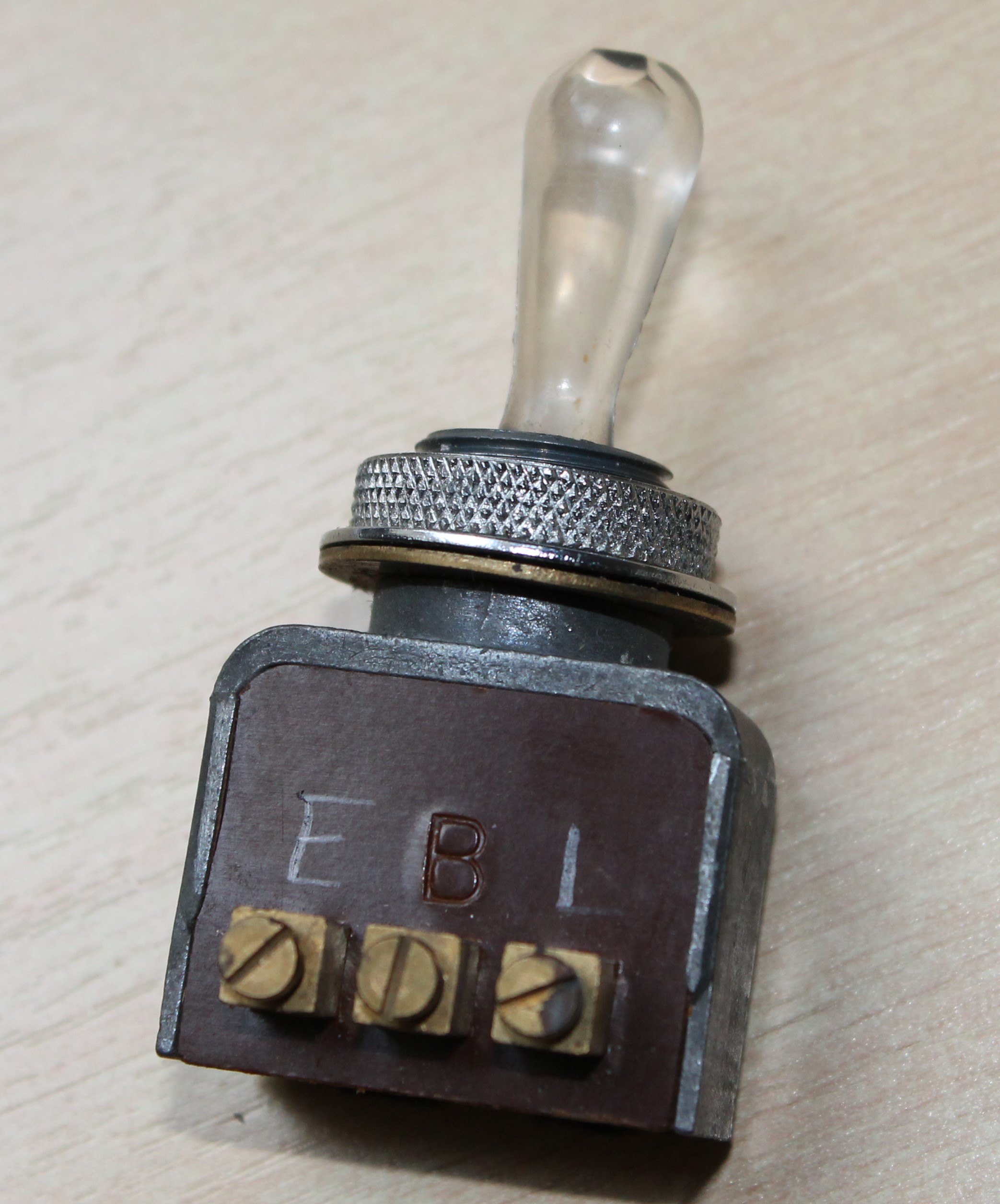
The conversions requires two modifications of the PS-33A switch:
1. After the bottom cover has been carefully removed it is possible to slide down the back wall of the switch. Beware of the ball that will jump out because of the spring behind it (see photo below right). A (semi-hard) rubber buffer of 12.7 x 10 x 7.0 mm is now placed (and preferably glued) in the aluminium housing at the side where the mark E has been put. This is done to block the third position. The 7.0 mm dimension is important and should be correct in order to allow the handle to rest in the centre position but not reach the third position.

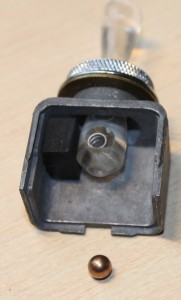 Rubber positioned
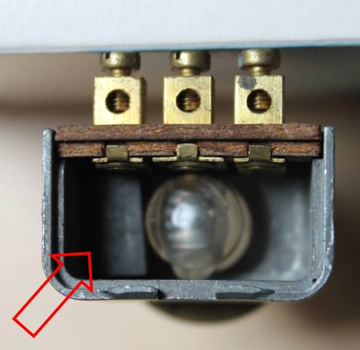

2. The warning light inside the PS-33A switch has two contacts. As the PS-4A has internal electrical connections, for the conversion external electrical connections have to be made to contacts E and L. The third contact B has an internal connection in case of the PS-33A but will not be used. There are two possibilities for making the electrical connections:
a. Simply connect the existing LH contact on the bottom plate to the E terminal of the back plate and the RH contact to the L terminal.
b. In case one would the PS-33A switch to look more like the PS-4A on the outside, then first remove the bottom plate and slide away the back plate (see photo above right). It is possible to (carefully!) remove the existing brass terminals on the bottom plate by pulling them out of the rivited brass connection. Then take two thin wires and solder them to the lamp contacts at each end of the bulb and connect one to the E and the other to the L connector on the inside of the switch.
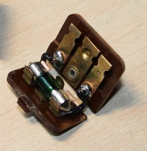 Internal connection made by soldering

The photo below shows the final result of the conversion (left) and an original PS-4A (right) for comparison.
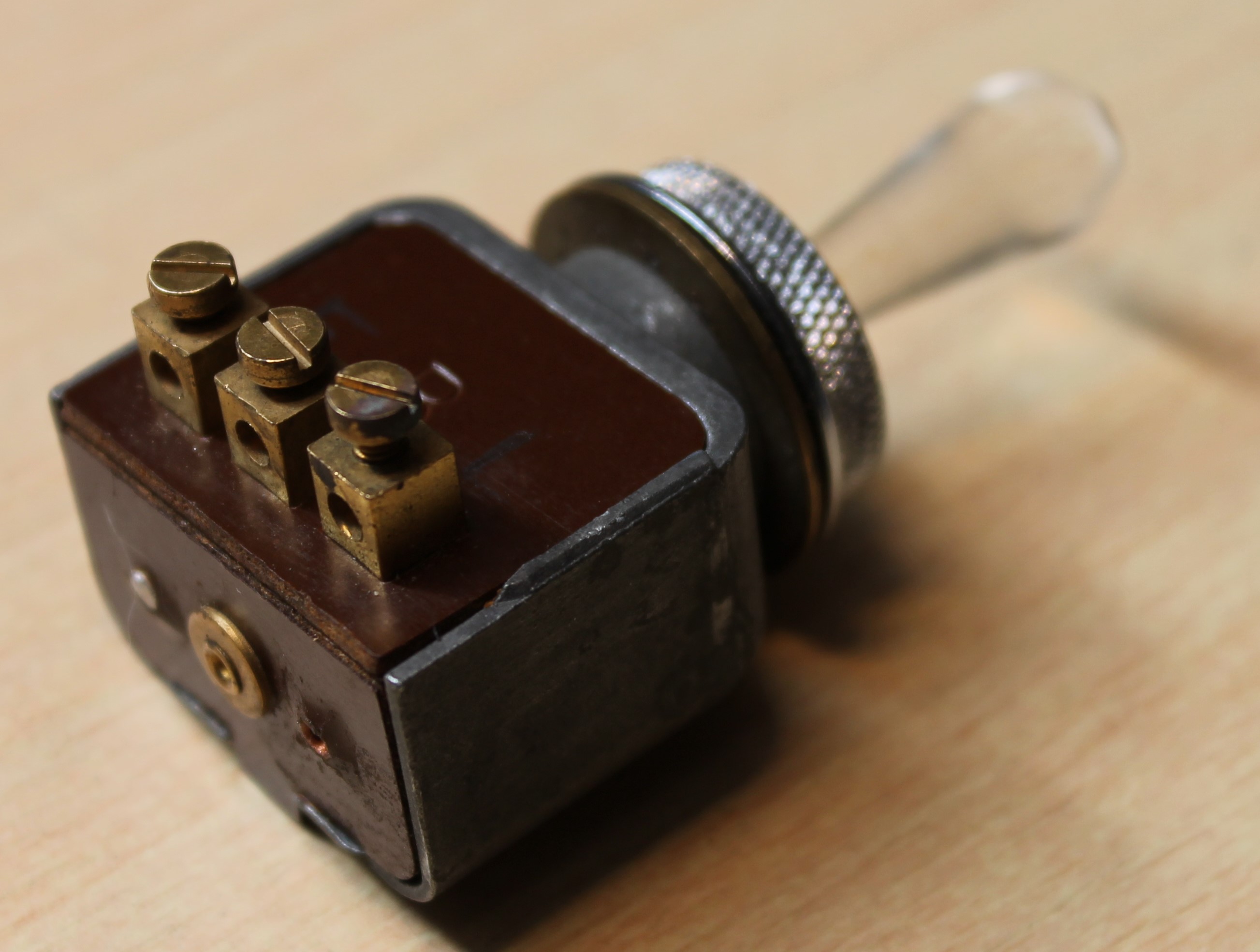
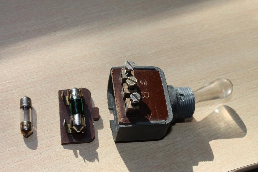
Trico washer-pump malfunctioning and repair
Introduction
The vacuum operated Trico washer pump units are basically all identical, although the vacuum and washer fluid connections may differ. The pump unit of the XK 120/140 is placed on top of the glass reservoir whereas the pump unit of the XK 150 is placed within the glass reservoir.

 Pump XK 120 & 140: bottom fixation nut Pump unit XK 150 (& Mk 1) with fixation nut at the top

The pump of the XK 120 and XK 140 (Jaguar Part Nº C.5473/3 or Trico Part Nº X.82540) have a brass lower dome half (photo below left) and an upper half made of high pressure die-cast aluminium (photo below right). The XK 150 version basically has the same pump unit (Jaguar Part Nº C.10127/3) but with a different vacuum connection (on top) of the aluminium housing (see photo above right).
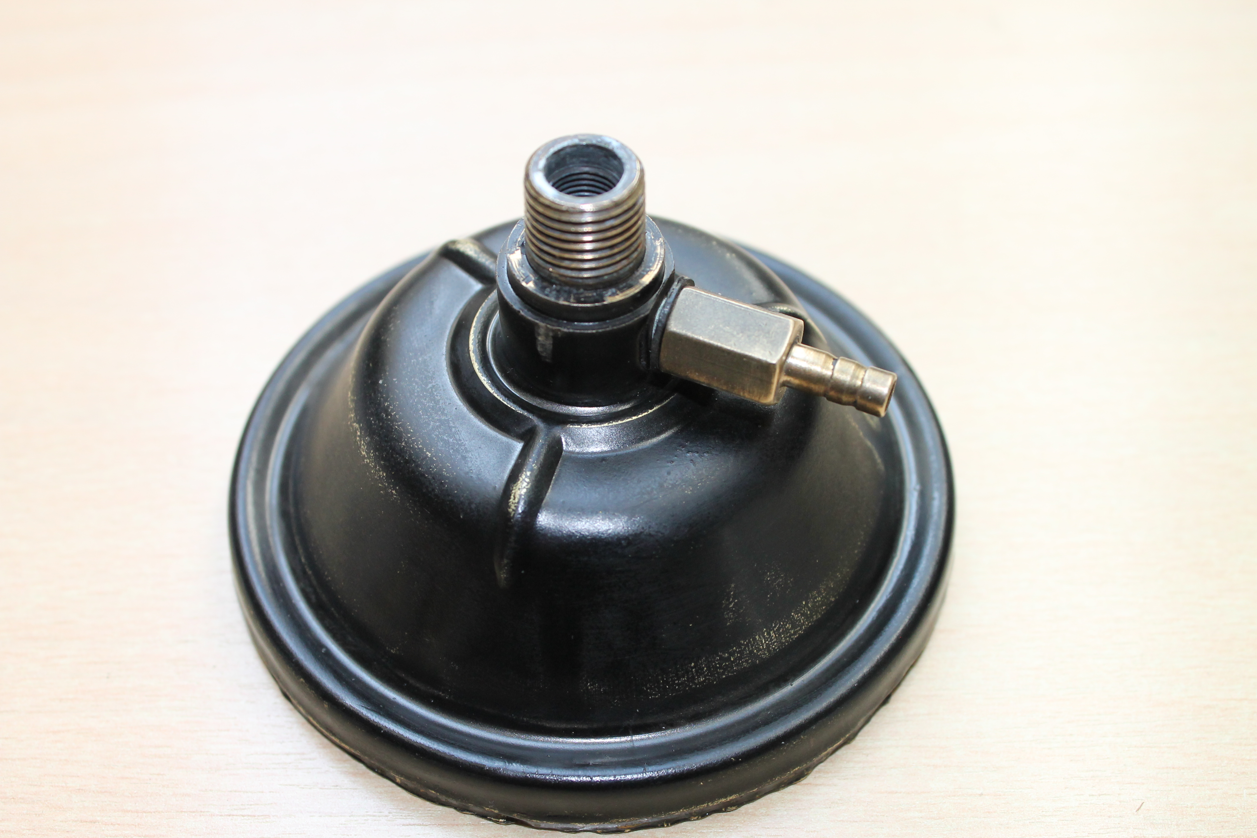
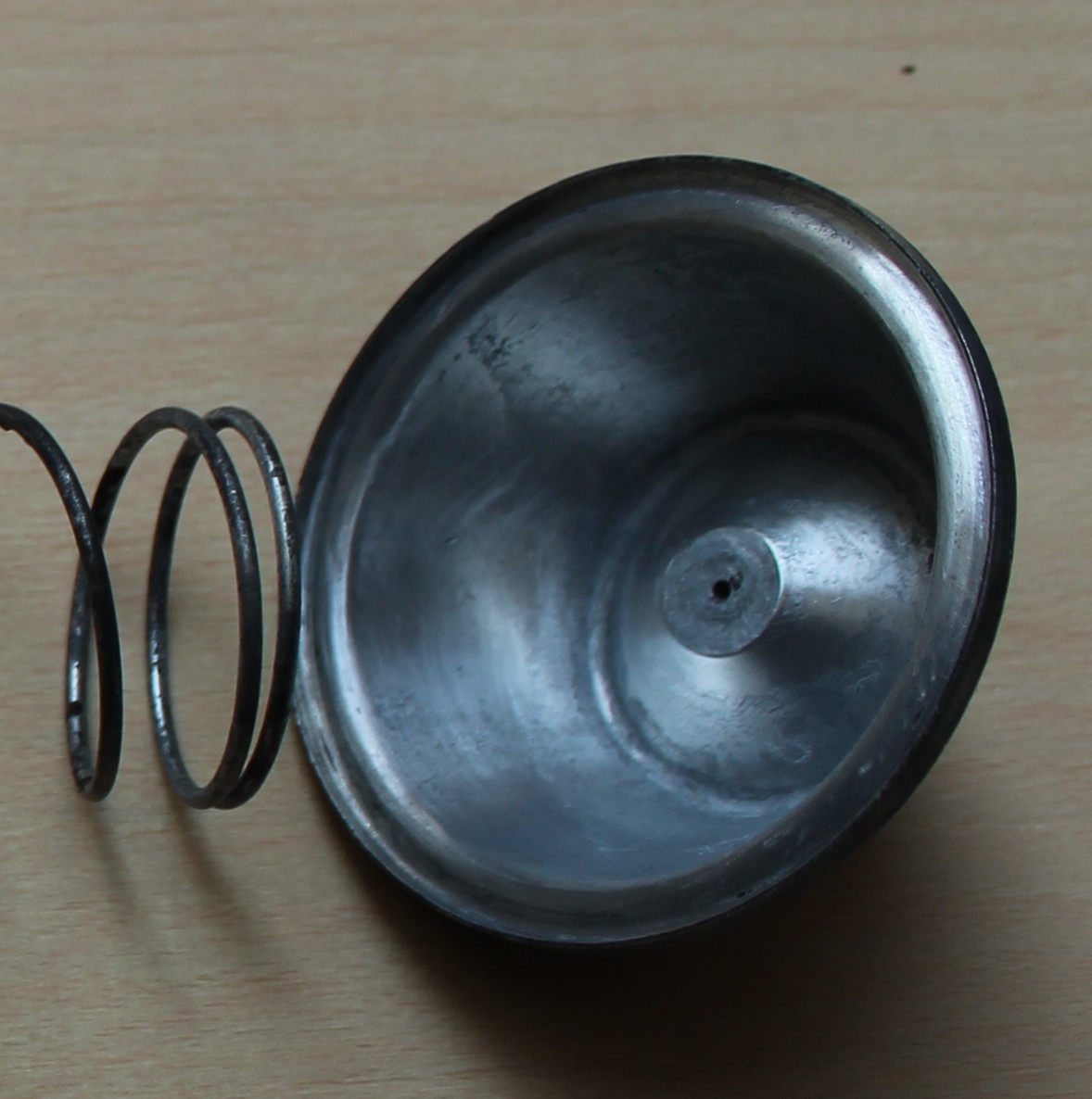
Over the years the rubber diaphragm will deteriorate, start leaking and eventually completely disintegrate: the pump has stopped working. See two examples below in different stages of disintegration.
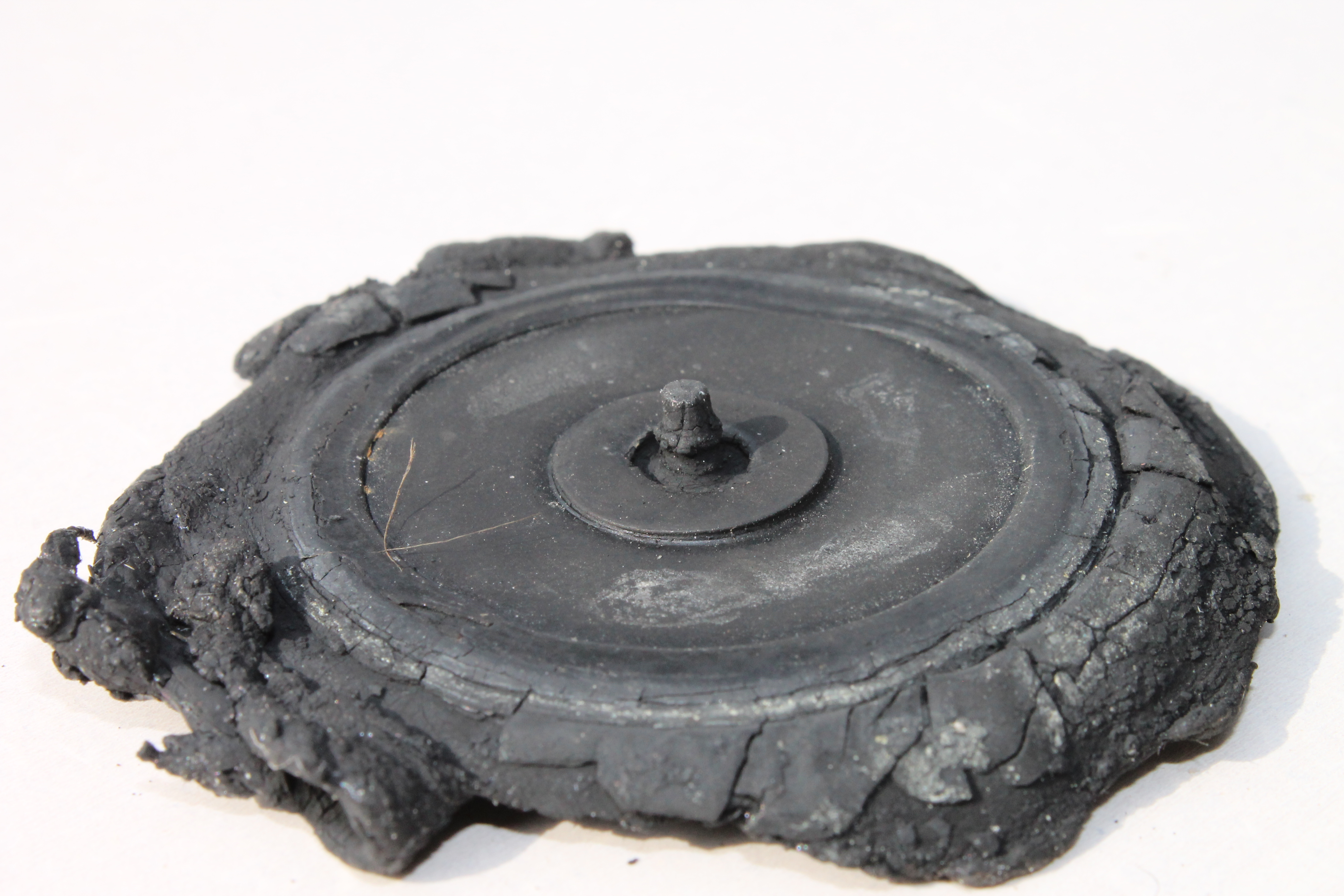
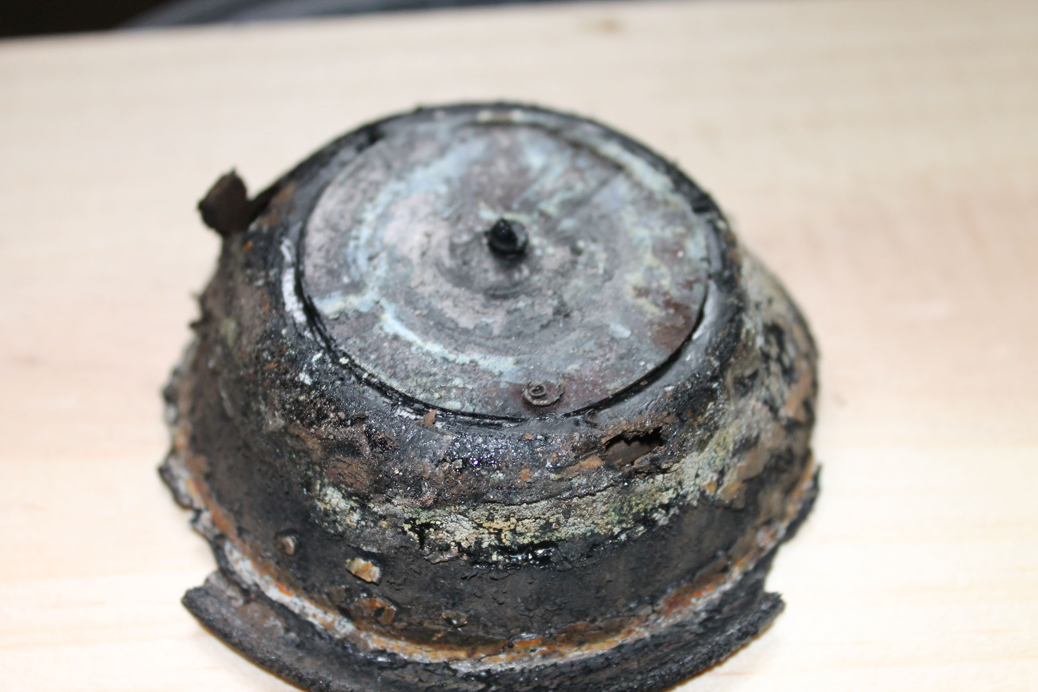
Replacement rubber diaphragms are not available (yet?), but some have been manufactured on a small scale. Assuming a replacement diaphragm is there, it is possible to repair such a Trico pump under the condition that the other components can be reused.
Construction
The two dome halves hold the rubber diaphragm (here shown in white but normally black). The diaphragm is pressed downwards in the brass part by a large spring. The rubber diaphragm has a brass “seat” to centre the spring at one side and a phenolic plate at the other side (see “exploded view” below).
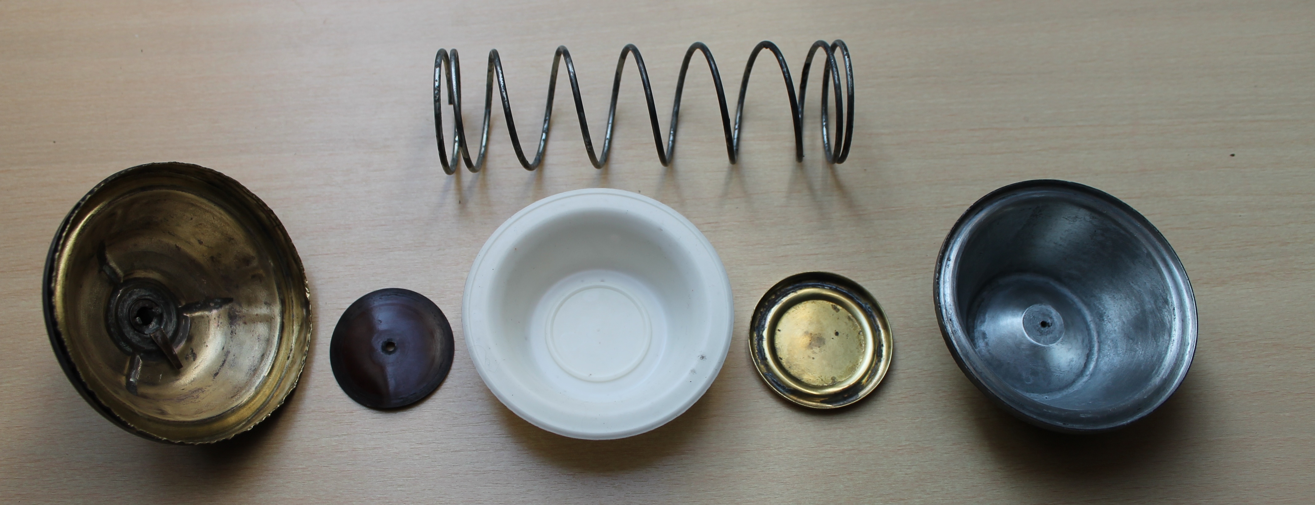
This phenolic plate is pressed down by the large spring and in turn operates a small spring arm at the bottom of the brass lower dome-half when no vacuum is present. This small spring secures that the check valve in the suction tube is open and can suck washer fluid from the glass reservoir into the dome.
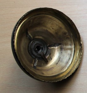
 Small arm operating check valve Second check valve in hose to washer jets

This check valve closes the “strainer” tube when vacuum is present above the diaphragm and prevents that water will flow back in the glass reservoir; this check valve consists of a steel ball and a spring . A second check valve is in the hose through which washer-fluid is pumped towards the washer jets. It is screwed in the side of the lower dome half and sealed with a fibre washer.
Repair step by step
It is possible (with a lot of patience) to open the rolled brass rim with a small screw driver. Try not to open the brass rim too quickly as otherwise the brass may tear or brake: take a small section and bend it open a liitle bit and then use a pair of pliers to bend the brass further to 90 degrees. Remember that there is a large spring inside, so keep both dome halves firmly together in your hand. The rubber diaphragm may have “glued” to the brass dome half and it may be required to separate the rubber from the brass using a screwdriver or chissel. Remove all parts as shown in the “exploded view”.
Clean all components and check for damage. Normally there is some corrosion on the inside of the dome that can be removed easily. Especially check whether the two surfaces that will hold the diaphragm are clean and smooth in order to obtain a perfect seal once the two dome halves have been “squeezed” together.
Place the components in the order as shown in the “exploded view” and note that the spring is rather long. Quite some pressure is therefore required to overcome the spring force and bring the two dome halves together.
It may be easier to make a special tool to hold the two dome halves under pressure while the edges are bent back to obtain a reliable mechanical seal.

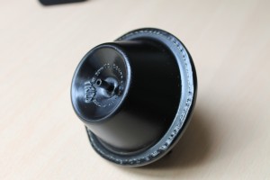 Simple tool to keep the dome halves together Finished product
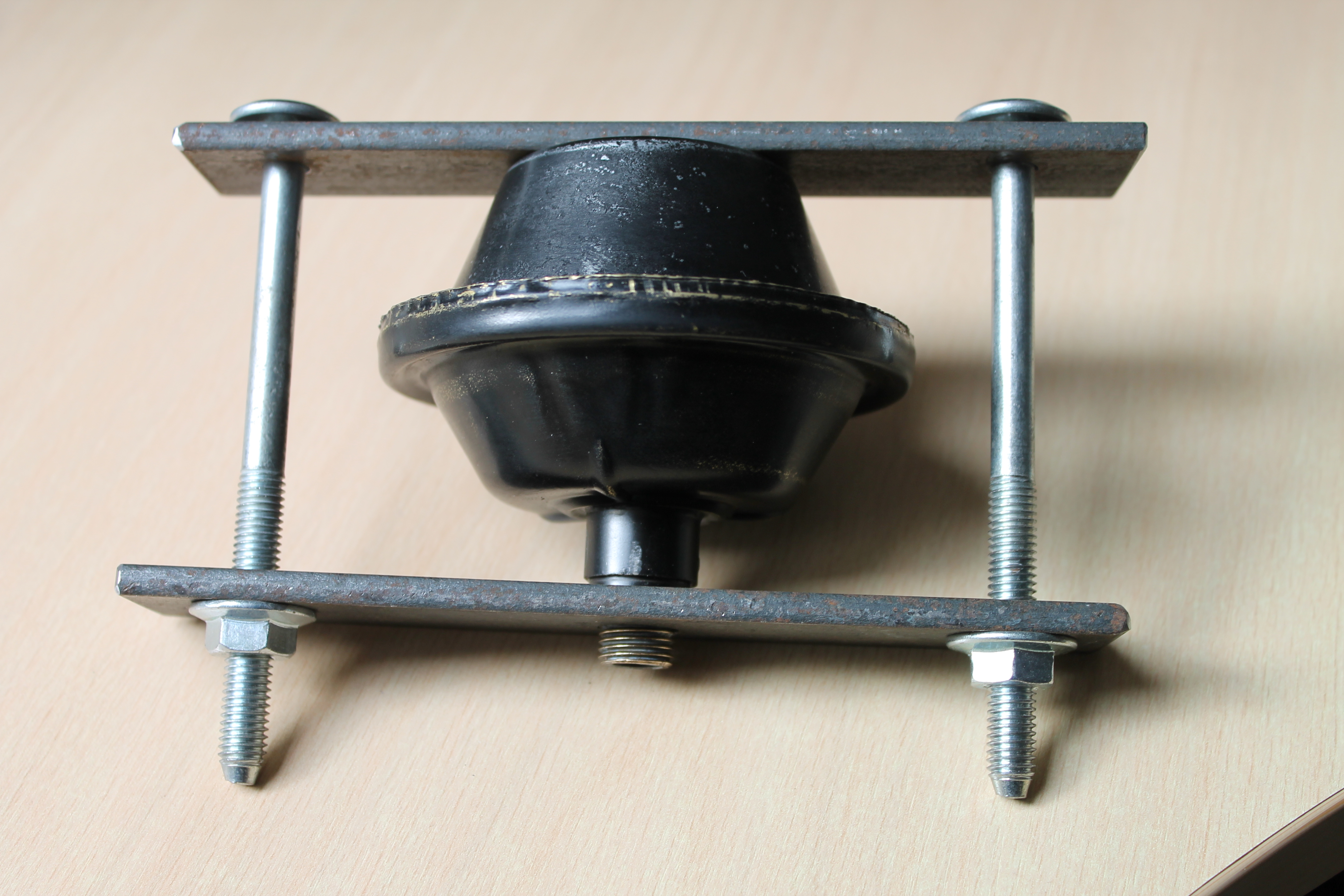

Carefully bent the brass rim back to a flat position, trying not to use excessive force from e.g. a steel hammer since this would stretch the brass (instead of shrink it). We may assume that Trico used special equipment to roll back the brass rim and we should try to come as close as we can to this mechanical operation (with simple hand tools). It is possible to obtain a good seal, although signs of the operation will remain visible (photo above right).
End result
It is very rewarding to see a 60 year old defective washer pump fully operational again. Complete washer pumps are available nowadays but they are rather expensive and may deviate from the original Trico design of the 1950’s: the XK 150 upper dome is sometimes also used for the XK 120/140 versions. Shown here is the “repaired” XK 140 FHC washer unit with the square bottle.
 Original XK 140 FHC Trico washer unit: fully functional

Brake light switch Jaguar XKs
Brake Light Switch Jaguar XKs
Introduction
Jaguar used a hydraulic brake light switch on all of their XK models (and many other types as well). This switch is screwed in the Outlet Adapter of the Brake master cylinder.
Brake switches (screw-in type) in general, use different threads which may lead to confusion when looking for the correct replacement. The thread used by Jaguar on these early hydraulic switches is rather special. Finding the correct version is of the utmost importance to avoid leakage or damage to the thread.
All XK brake switch types had an 1/8″ x 27 NPTF (external, male) thread. This is a special screw thread derived from the US National Pipe Thread. NPTF is an abbreviation for National Pipe Taper Fuel and “Oil-dry-seal” thread. This conical thread is designed to provide a leak-free seal. NPTF threads have the same basic shape as NPT but the thread is adjusted to obtain an interference fit, eliminating leakage along the thread. All NPT threads have a taper of 1 : 16 on the outer diameter of the thread, which equals an angle of about 1¾ °.
 Male NPTF thread on brake switch
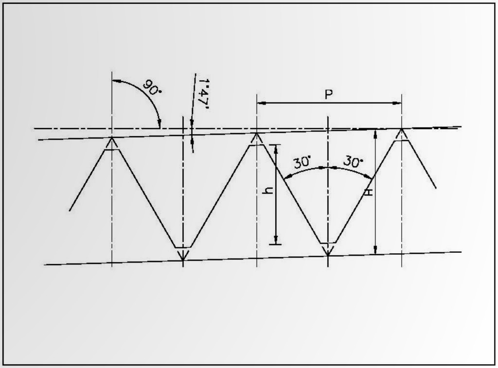
Please note that the corresponding (internal, female) thread of the adapter is 1/8″ x 27 NPSF, which is a straight (non-tapered) thread.
- The outer diameter of the 1/8” x 27 NPTF is 10.3 mm and the pitch is 0.94 mm.
- The modern version of this brake light switch has a metrical thread coded M10 x 1 and it is therefore easy to get confused and use the wrong version on an XK. Always check whether the correct NPTF thread is being used!!
- A third type of brake light switch has an UNF 3/8”x 24 thread (with an external diameter of 9.5 mm). Also avoid this version as (again) the thread will be destroyed by installing this UNF thread.
The following hydraulic brake light switches have been used by Jaguar for their XKs:
1. Jaguar XK 120
- Early cars manufactured until January 1953 (chassis numbers up to 660979, 669002, 67048, 679621, 667000 and 677000) had a brake light switch produced by Lockheed: Jaguar code C3901 and Lockheed part number 23388. The switch has long screw studs for the electrical connection and can be easy recognised.
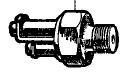
 Lockheed Brake light switch 23388
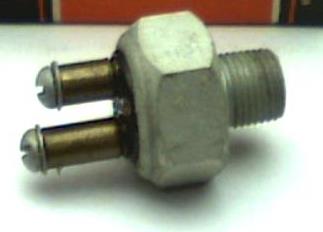
- With the introduction of the Tandem brake cylinder type, the XK 120s changed to a Lucas brake light switch with Jaguar code C5218 and Lucas code 31082/B.
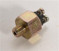
 Lucas switch 31082/B to F; photo right original Lucas; photo left possible later version
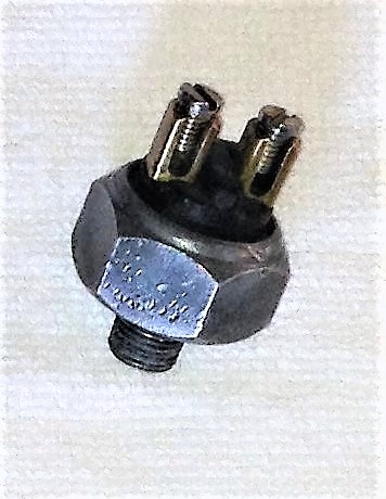
2. Jaguar XK 140
The XK 140 continued the use of the Lucas brake light switch with Jaguar code C5218 and Lucas code 31082/D, mounted in the Outlet Adapter of the Master Cylinder.
3. Jaguar XK 150
The XK 150 also used the same brake light switch but the Lucas number 31082 had meanwhile received suffix F. The switch was mounted in the Outlet Adapter of the Master Cylinder.
Replacement alternatives:
This type of brake light switch can be or was used on many Jaguars : besides the XK120, XK140 and XK150, also on the Mk VII, VIII, IX, the Mk 1, Mk 2 and successors, the E types and even the XJ types
It will be very difficult to find an original C3901 Lockheed switch, but fortunately the later C5218 versions fits without a problem and is still available as an aftermarket version (see list below).
Brake switches for later Jaguar types (code C16062 and Lucas 31802/D) used Lucar connections instead of screw connections, but are otherwise similar.
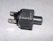 Jaguar C16062 (Lucas 31802/D) with Lucar connectors
The generic Lucas replacement brake light switch for the 31082 and 31802 is coded Lucas SPB400 but has Lucar connectors.
Other alternatives part numbers: (not all versions have been confirmed)
- BMC/British Leyland 3H1894
- Bosch 0 344 004 011
- Bremi 10760/13
- Bremi 10760/19
- Intermotor 51600 Lucar connectors
- Intermotor 51620 Screw terminals
- Lucas 34542
- Lucas 34765
- Lucas SMB 423
Flashing direction indicators on XKs
Flashing direction indicators on Jaguar XK
From Trafficators to Flashing indicators.
After the introduction of the XK120 the first open versions (OTS) had been delivered without any form of direction indicators. The Jaguar Saloons of that period had the so-called “Trafficators” (or “Semaphores”) installed.
 Trafficator on Jaguar 1½ litre Saloon
By October 1952 most Jaguar XK120 models had switched over to “flashing direction indicators”, although (according some catalogues) “Home Market” versions may have continued without direction indicators. The XK120 with flashing indicators required “combined bulb functions” at front and rear as no dedicated direction indicator lamps had been foreseen in the initial design.
- At the front single filament bulb Lucas 490 side lamps changed to double filament Lucas 513 side lamps with Lucas bulb 361 (12V 6/18W).
- At the rear the existing Tail/Stop lamps Lucas model 488 also received an additional function: the 18W brake filament of the Lucas bulb 361 (12V 6/18W) now also acted as flashing indicator.
This was only possible via the installation of a special Lucas double relay (model DB10) that interrupted the brake light in favour of the flashing indicator function when the direction indicator switch was operated. The other brake light kept its normal function to show that the vehicle was braking.
 Typical Lucas double relay DB10
The combined direction indicator function for front and rear lamps changed in two steps:
- At the front, dedicated Lucas L563 direction indicator lights were fitted late 1954 on the occasion of the introduction of the XK140
- Dedicated rear direction indicator lights only arrived in October 1959 when the XK150 changed over to Lucas L627 rear lights with a separate amber or red (USA) direction indicator lens. At that moment also the double relay DB10 was deleted.
The flasher unit.
In the direction indicator system the role of the flasher unit is crucial. The flasher unit is a switch that (in simple words) interrupts the power supply to the bulbs when the current through the wire heats up a spring and restores the connection again when it cools down and all this in a fraction of a second. The rate of flash is normally between 60 and 120 times per minute.
Although difficult to imagine nowadays, the flashing indicator was a new product in England (and the whole of Europe in fact) after WW2 and first development dated from 1949 (Bosch of Germany). In the UK it took until early 1953 before Lucas could supply such units (the FL2 flasher unit) to the British automotive industry.
Introduction of flashers on Jaguar XKs
First flasher units for 1952 Jaguars including XK 120 have been delivered by the Tung-Sol company of Newark, New Jersey, USA. This company (famous for its automotive bulbs but even more for radio tubes) made the first steps towards a “flashing turn devise” in the 1920s. From the 1940s onwards most US car models had these flasher units.
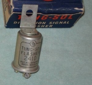
 Original Tung-Sol 241D
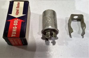
 Later version

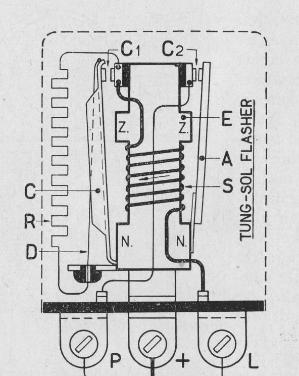
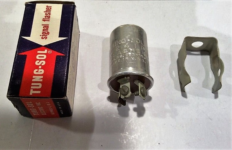
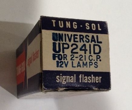
The Tung-Sol flasher unit is a complex devise using both “thermal expansion” of the metal arms as well as “electro-magnetism” to open and close the points.
The flasher used by Jaguar was part number Tung-Sol 241D which is a flasher units suitable for switching 2 x 21W (total 42W) including a (“Trafficator”) warning light. Jaguar used in that period 2 x 18W bulb power plus a 2.2W warning light in the instrument panel (total power about 38W).
Note the following Service Bulletin 112 of October 1952: “Cars scheduled for export are fully wired for flashing indicators and have relay units fitted. Owing to shortage of supplies, Tung-Sol unit part number 241D is not included for certain countries, and it is the responsibility of the Distributor to ensure that unit is obtained locally and fitted prior to delivery”.
The Jaguar part number for the Tung-Sol 241D flasher was C5230.
The Tung-Sol flasher has three screw contacts at the bottom marked + (for battery), L (for direction indicator lamps to be switched) and P (for pilot or warning light). The flasher had a vertical bracket with mounting hole. Also note that the early Tung-Sol flashers had the product data printed in black on the aluminium can.
Change-over to Lucas flashers
Lucas had developed in the meantime their first flasher units. The FL2 (Lucas part number FL35002) had been introduced early 1953. A revised version model FL3 arrived late 1953 with Lucas part number 35003/A which was consequently used in the XK120 production. Note that Jaguar part number remained C5230.
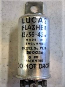
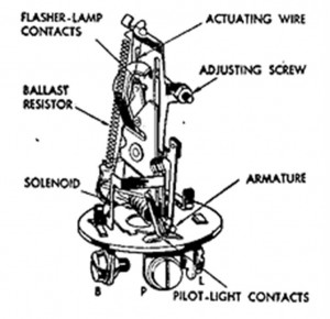 Lucas FL 3 35003A


The Lucas FL3 flasher unit is basically identical to the earlier Tung-Sol version. Also note the exact details of the (copied) screw connections. Even the marking was identical apart from + which changed into B (for battery); remember Jaguars had positive earth. Also Lucas started with printed product data on the outside of the aluminium flasher housing. This flasher also had a vertical bracket with mounting hole.
The Lucas FL3 (35003A) was continued for the year 1954 when the Jaguar XK140 was introduced and remained standard fitment until early 1957. The XK 140 received dedicated direction indicator lamps at the front (Lucas L563) and thus the Lucas 513 side lamps changed from double filament to single filament bulb holders with Lucas bulb 207 (12V 6W). We note that all Jaguar XK 140s had the FL3 as standard equipment.
From FL3 to FL5 flasher units
Early 1957 the FL3 was replaced by the FL5 flasher unit (Lucas part number 35010A). Jaguar part number remained (again) C5230. The internal construction had changed and the aluminium housing had a larger diameter but it was shorter than the FL3.
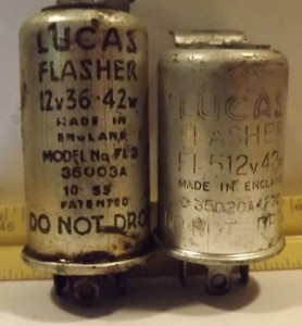 Comparison FL3 versus FL5 (courtesy Marvin Moore)

The FL5 remained the standard version for many years until it was replaced in the 1980s by the 8FL version.
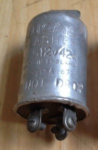
 FL5 flasher 35010A
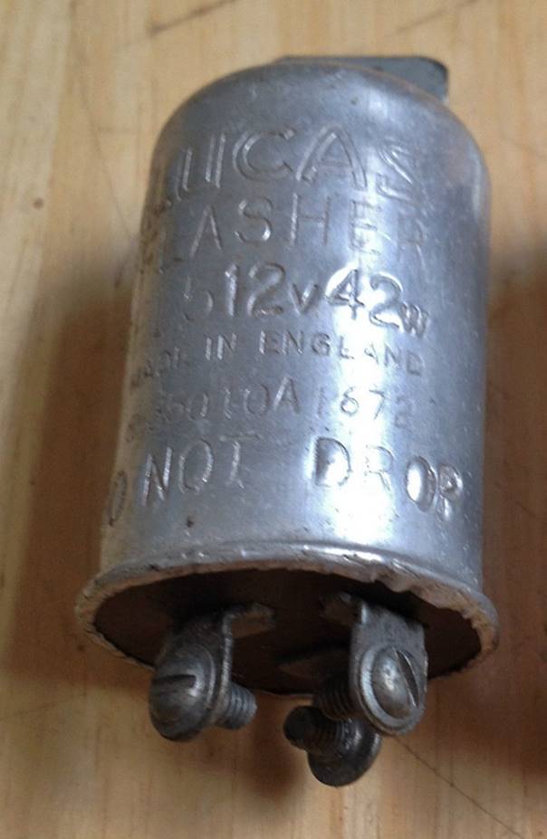
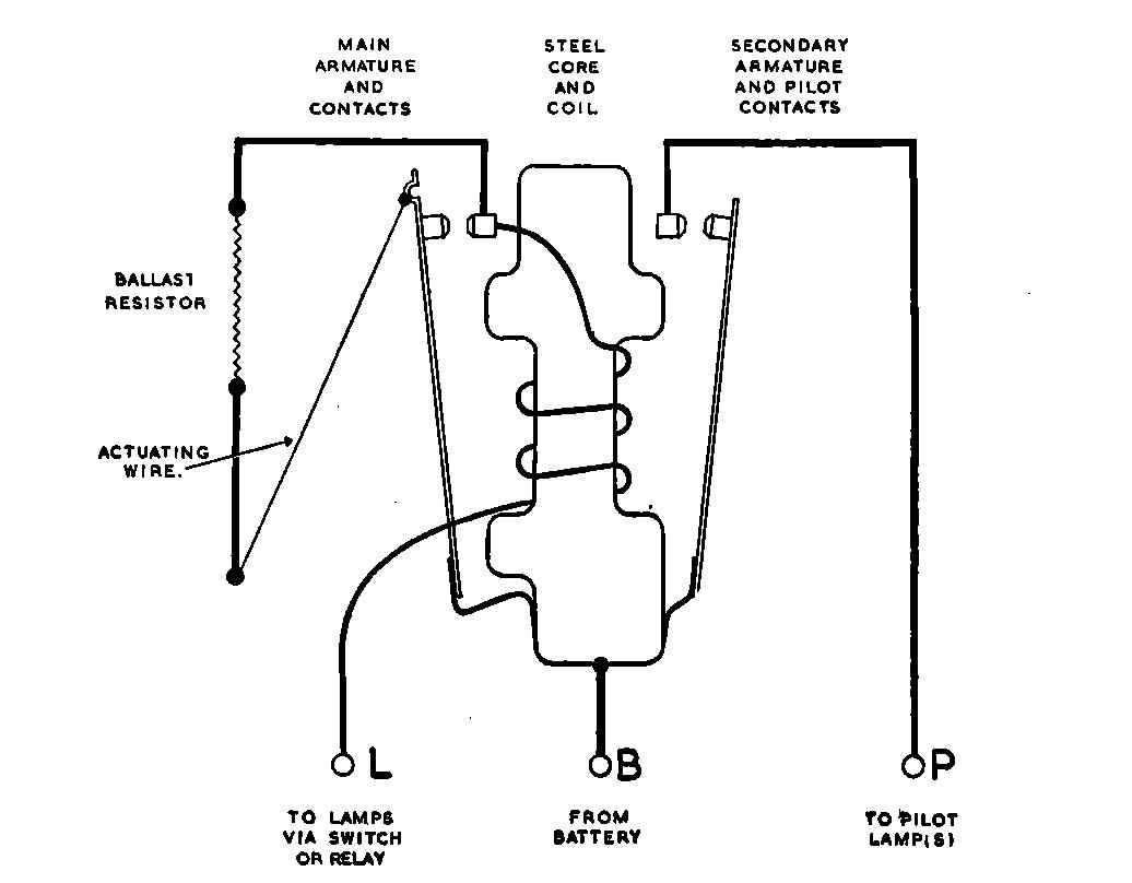
The FL5 flashers kept the 3 screw connections and the marking was still B, L and P. But Lucas changed from printed to stamped product data on the outside of the aluminium flasher housing. The 35010 flasher continued the vertical bracket with mounting hole.
The Jaguar XK150 started life in February 1957 with the new Lucas FL5 flasher. It continued the direction indicator lamps (front and aft) of the Jaguar XK140 until dedicated rear direction indicator lights arrived in October 1959. The XK150 changed over to Lucas L627 rear lights with a separate amber (or red for USA) direction indicator lens. At this moment also the double relay DB10 was deleted.
Overview of flasher versions for XK120, 140 and 150.
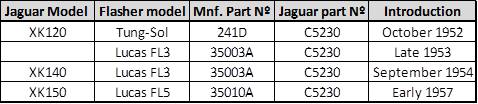
Lucas Flasher product range
Lucas extended their range of flasher units gradually over the years. In fact only the FL3 and FL5 models are of interest to the Jaguar XK owner. As far as originality is concerned, the FL3 version is by now almost impossible to find but the early FL5 version with 3 screw contacts can still be found as it has been manufactured until the 1970s in large quantities.
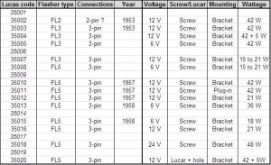 Survey of Lucas FL3 and FL5 flashers
Lucas introduced the “Lucar” connectors (replacing the screw contacts) in 1960. These flasher versions are (functionally) identical to the earlier 35010 version, apart from the Lucar connections at the bottom. We are also looking for a vertical bracket with mounting hole, because there are also other versions without a vertical bracket, e.g. Lucas 35011. These flashers require a separate mounting clip and also sometimes have a special connector which looks very similar to a 3 pin bulb holder as used for Sealed Beam lamps in the 50s and 60s. This construction allows for a quick replacement of a defective flasher unit. Note that in some cases the connector block is fixed to the car body with a screw (RH photo below).
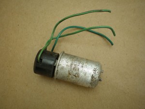
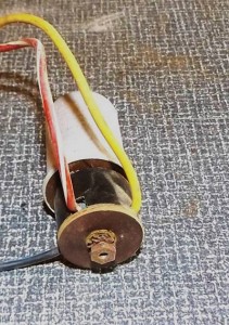 Lucar connector block

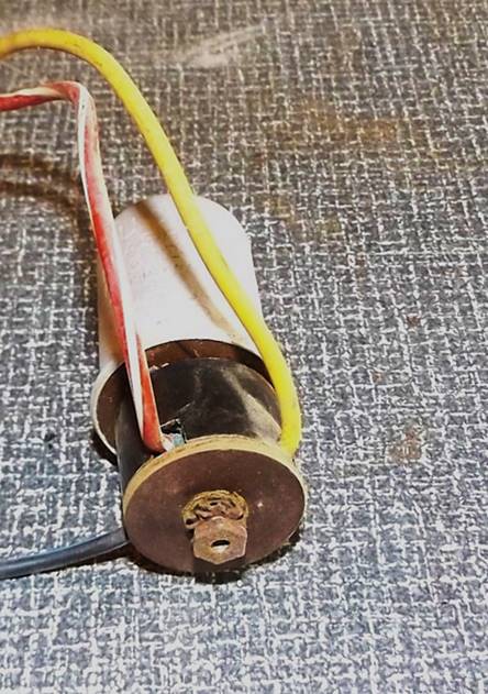
Trico illuminated (overdrive) switch
Trico illuminated switches
Besides the well-known vacuum equipment for wipers and washers, Trico also manufactured a large variety of switches as part of their programme for the automotive industry. One of the most “famous” versions is the PS (Pilot light Switch) range with an illuminated, transparent handle. This is a specific UK developed and manufactured product.
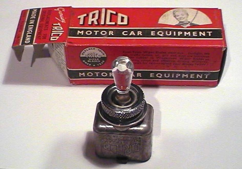
Switches have been supplied during the 1950s and 1960s after which production in the UK ceased.
 1951 advertisement with Trico PS type of switch
The Trico PS (Pilot light Switch) range.
The range consisted of at least 7 versions (but possibly more), each one intended for a specific application like:
- 2 or 3 positions (1 way or 2 way switch)
- specific load to be switched
- which signalling function required
- required bulb colour
- 6 Volt or 12 Volt execution
The switch is to be mounted in a panel using a ⅝” or 16 mm hole. A chromed knurled ring, acting as nut, secures the switch to the panel.
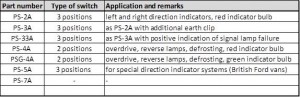 Survey of PS switches
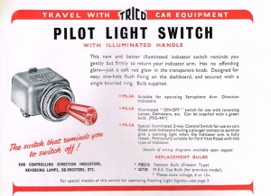 Catalogue 1953 (courtesy Roger Payne)
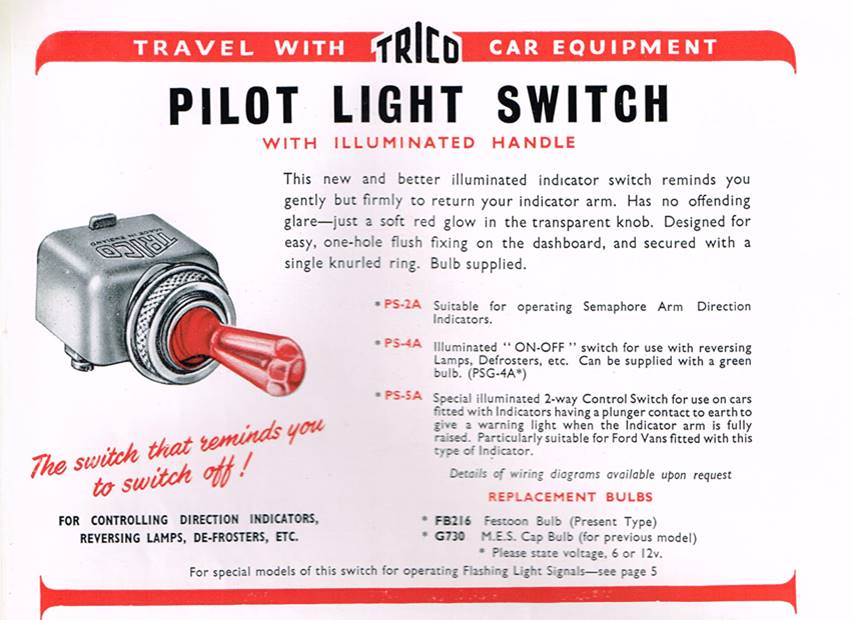
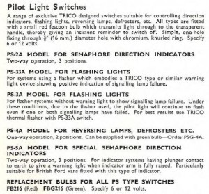
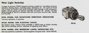 Catalogue 1959 Catalogue 1960
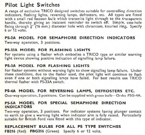
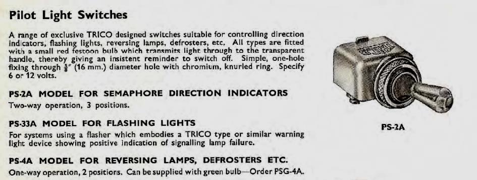
The PS switch construction
All switches used the same aluminium die cast housing, suitable for 3 positions. The signal lamp was positioned on a (thermoset) plastic cover at the bottom of the switch, whereby the number and position of contacts depended on the signalling function.
In case of a 2 position switch a rubber buffer was placed at one side within the aluminium housing blocking the 3rd position.
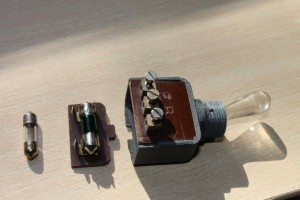 Typical construction
Jaguar application of the PSG-4A switch
Although Lucas recommended their manual overdrive switch type 9RW (Lucas part number 31587 or 031648) in combination with Laycock overdrives, Jaguar instead opted for a Trico switch in spite of the very close relation with their “preferred supplier”.
Lucas overdrive switch 9RW used on Armstrong Siddeley and Triumph
In 1954 Jaguar introduced the PSG-4A as an overdrive switch on the XK140 (and other contemporary models like the Jaguar Mk VIIM and Jaguar Mk1) with Jaguar part number C7474. This switch had 3 screw terminals of which two were marked: the middle had the letter B (battery) and the other with the letter E (earthing the signal bulb). The third (unmarked) contact is connected to the Overdrive Relay(s). This switch originally had a green “festoon” bulb (although many may have received a white replacement bulb in the past decades). The replacement Trico bulb FBG216 received Jaguar part number C8829.
Note that the PS-4A version is normally supplied with a red bulb, but Jaguar opted for the green bulb.
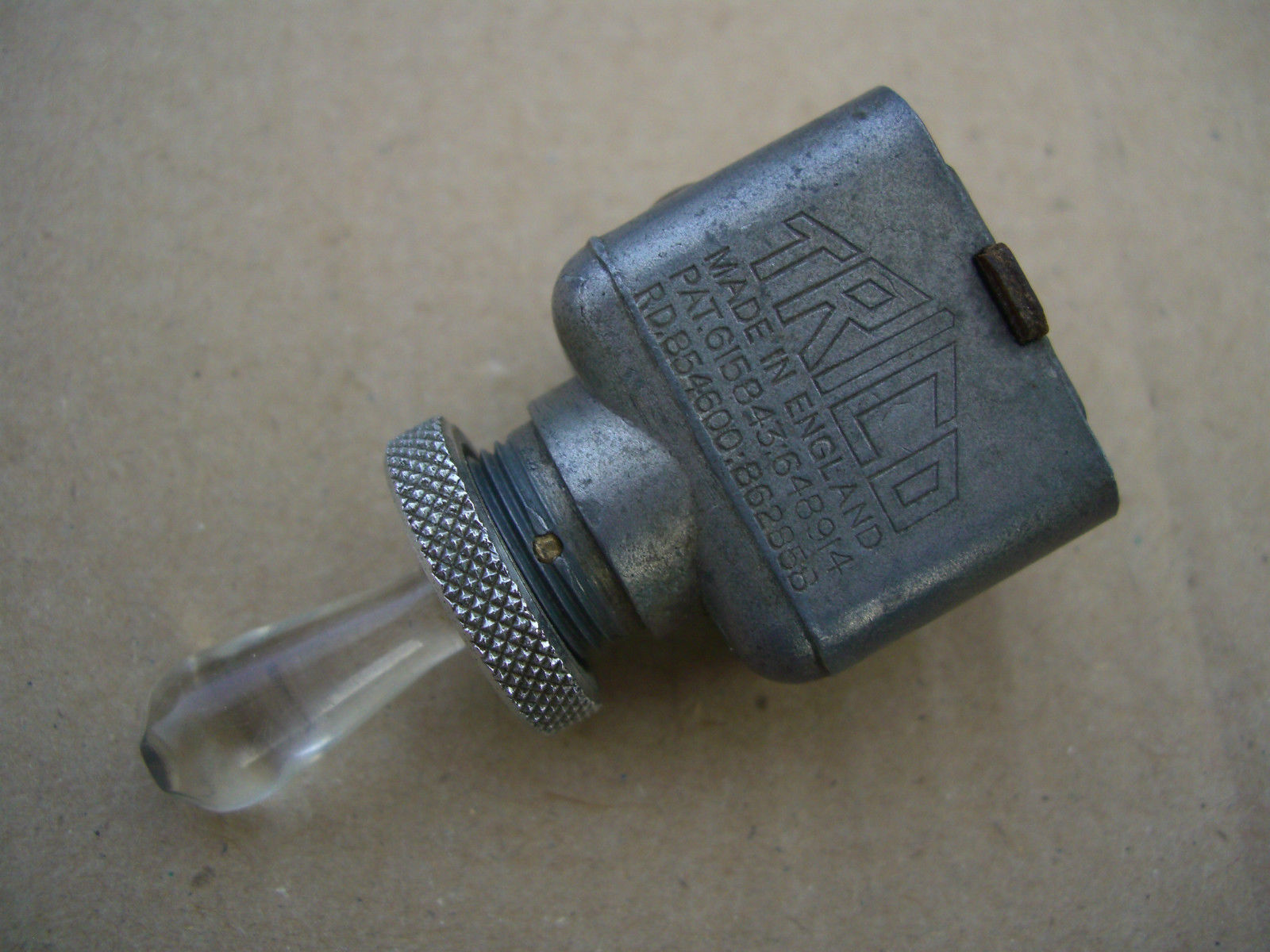
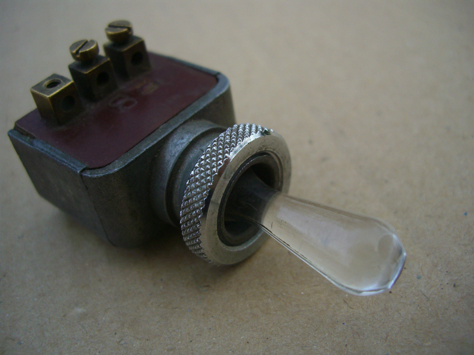
Note: For the XK150 Jaguar changed over to part number C12832 (81053 JSB) which is not further discussed here. Also the Mk2 used a different (Lucas) switch type 52SA with Jaguar part number C15611 (Lucas part number 31965A) followed by SA52 type switch with part number C23391 (Lucas 34804).
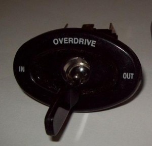
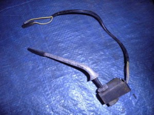
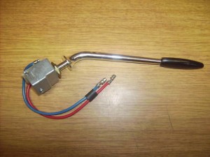 C12832 C15611 C23391
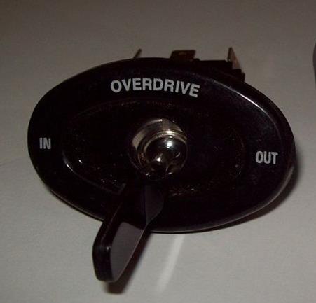
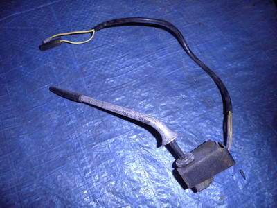

Examples of other Trico PS switches
The PS-33A is used as a direction indicator switch. It has additional screw terminals for the festoon bulb at the bottom of the switch. It is not a direct replacement for the Overdrive switch PSG-4A.
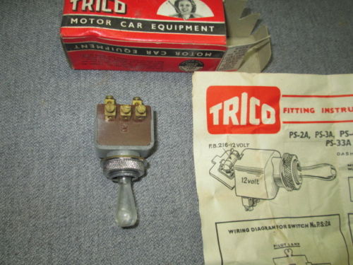

 Complete box with 6 pcs Trico PS-33A
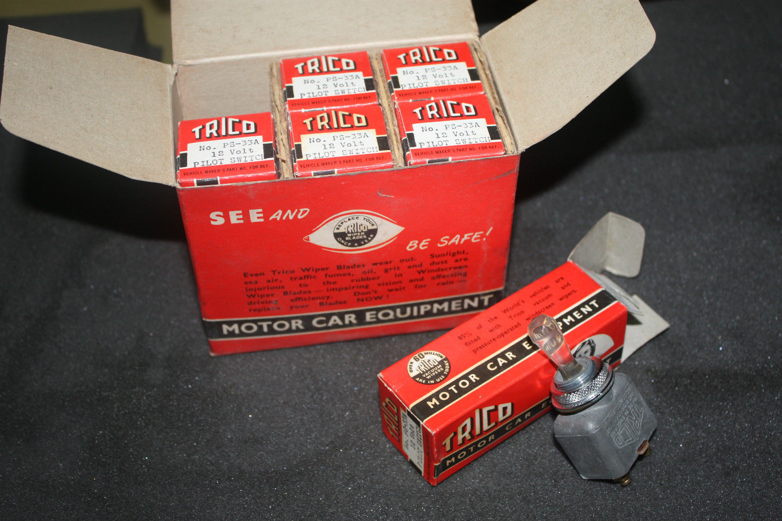
Trico “Festoon” bulbs
The bulb was of the “festoon” type and was supplied by Trico. There are 2 known bulb colours: red and green. The Trico part number for the built-in indicator bulb is FB216, which is a 12V 1.5W festoon green bulb of 22 mm length. Trico provided a large range of “festoon” bulbs: only the FB216 version was correct for the PS switches.
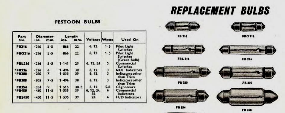
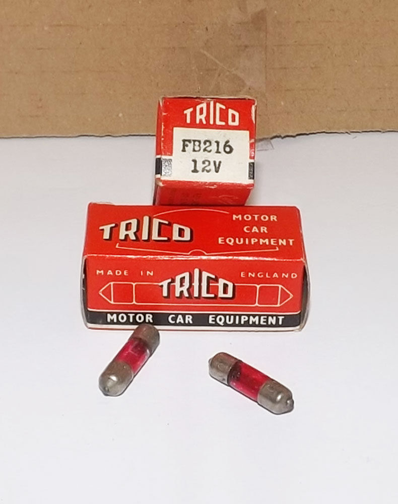
Green replacement bulbs are very hard to find. In Germany a similar bulb type is coded S6 (6 x 24 mm) 12 volt available in either 1.2 W or 2.0 W with S5.5 bulb contacts. The standard diameter of the original Trico bulb is 0.216” or 5.5 mm so the S6 version will fit. Sometimes available in green but 2W instead of 1.5 W (e.g. Scharnberger 25929).
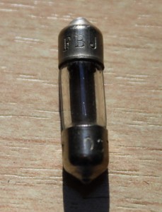 Replacement bulb FBJ 216 (S6 6 x 24 mm 12V 2 W)

Headlight Bulb Holders/Adaptors for XKs
Head lamp Bulb Holders (Adaptors) for XKs
1. The PF770 range for XK120
XK120s destined for the UK (“Home Market”) had the larger PF770 head lamps (7¾” or roughly 200 mm diameter) and used a dedicated LH and RH lamp per car of which one had a double filament and the other a single filament. XK120s for other countries (as far as legally allowed) had these PF770s with two double filaments lamps for both LH and RH.
All double filament lamps used Lucas Bulb Holder 554602 (double contact and 1½” or 38 mm in diameter) with 3 wires of suitable length and a rubber grommet. This assembly may have been initially made for Jaguar only. It had Jaguar part number 3581 and received Lucas part number 858543. The single filament head lamp of the early Home Market XK120s (Jaguar part number 3580) had Lucas assembly 858540 consisting of single contact Bulb Holder 554607 and only 2 wires of suitable length and a rubber grommet.
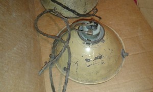
 Bulb holder assy 858543 for the PF770 light unit (left). Note large lamp opening in the reflector (right)
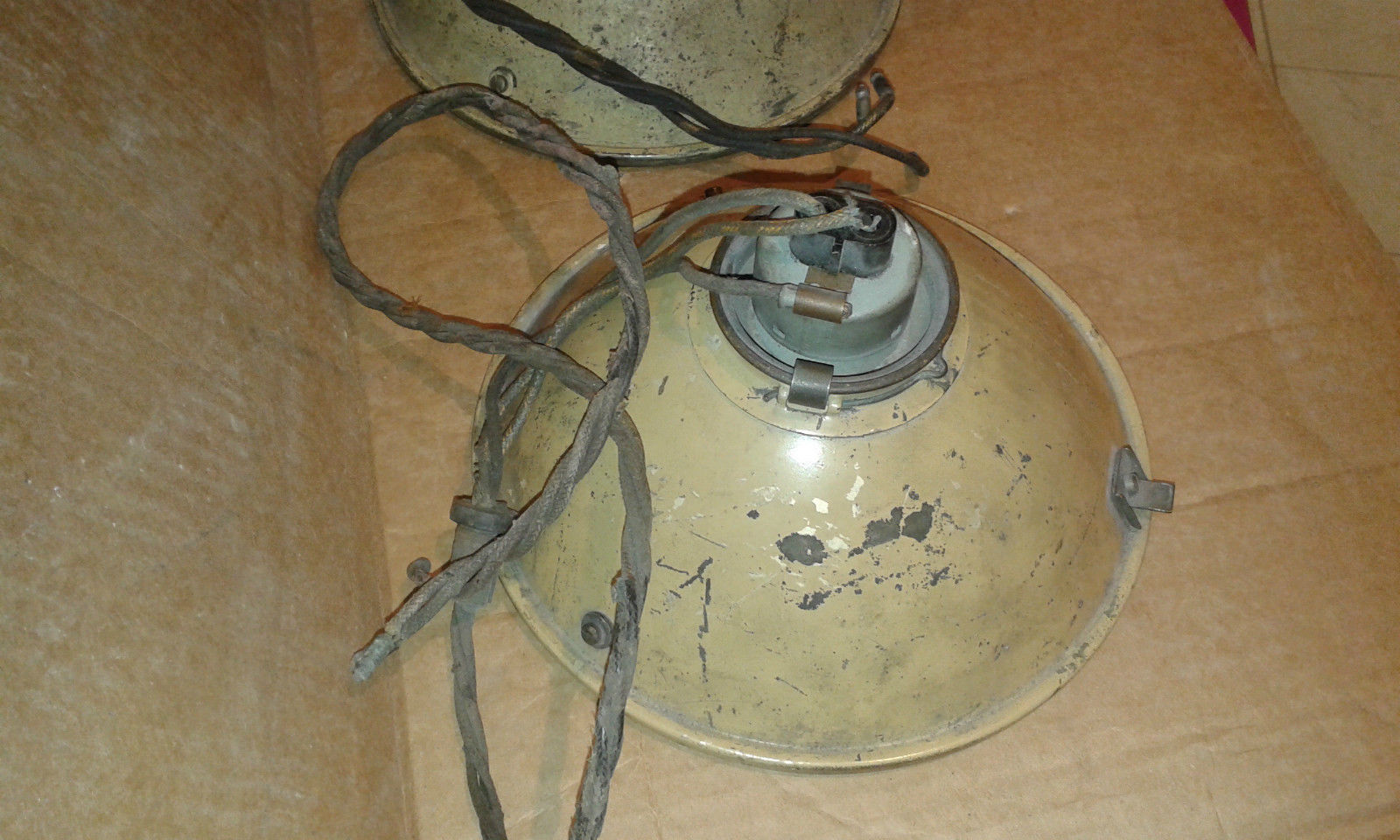
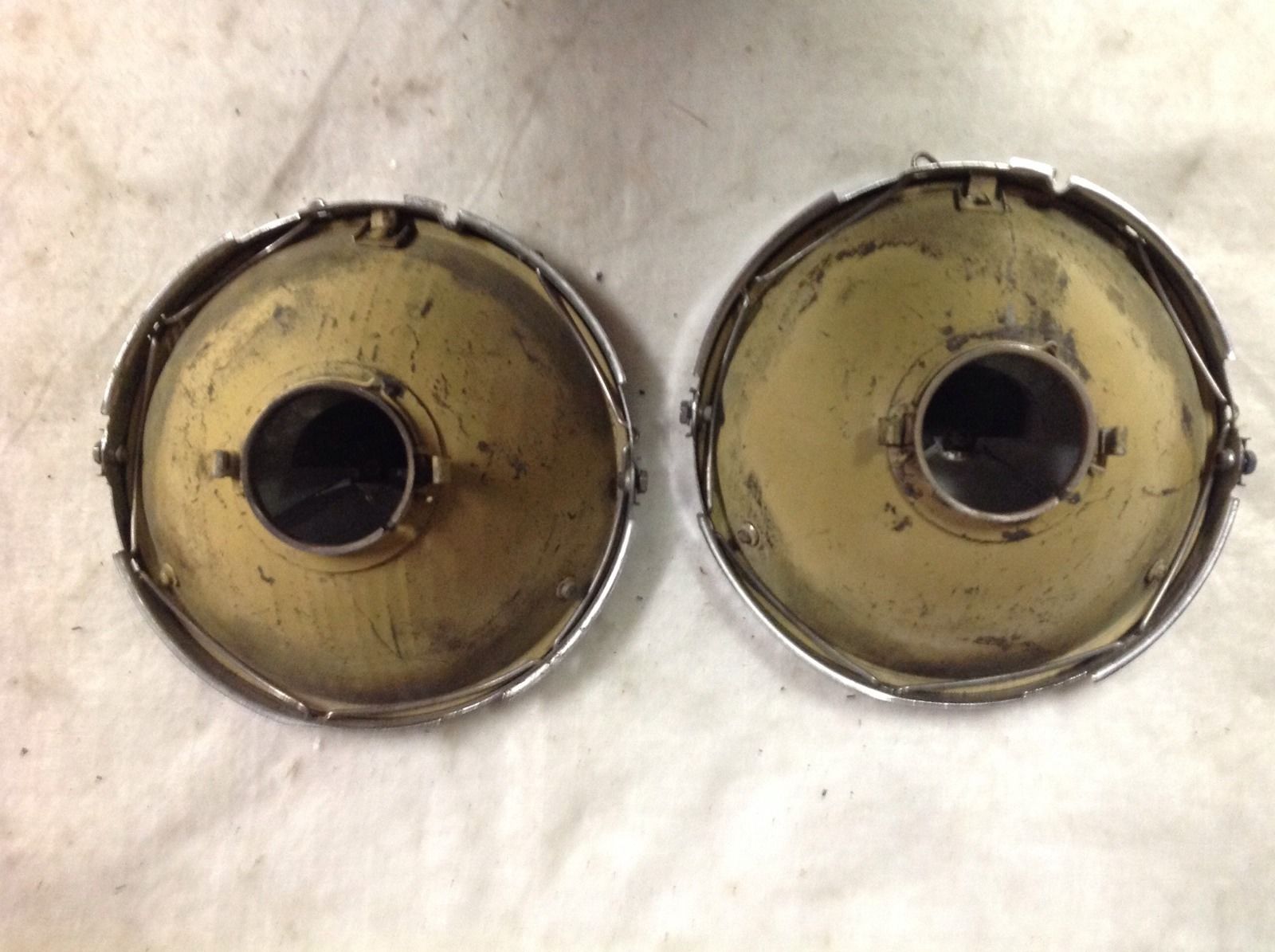
The reflector had a large opening, necessitating the use of a “Back shell assembly” or “Shell adaptor” (Lucas 553480) which in fact is a part of the reflector closing the gap between light unit and bulb holder.
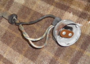
 Detail of Bulb holder assy 858543 Shell adaptor 553480 fits in reflector opening

2. The “J 700” lamp range for XK140 and XK150
XKs with “J 700” lamps used Bulb Holder Lucas 554855 for the BPF bulb Lucas 404 (60/36 Watt). This bulb holder has 3 wires with a length of about 36” (90 cm) with a black plastic sleeve over these wires. Bulb holder 554855 fits within the round opening at the back of the reflector and has three “pins” that fit in the corresponding holes (see photo) in only one defined position (the so called lamp base “key”).

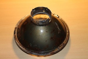 Bulb holder 554855 and Shell adaptor 554909 Larger reflector opening in J 700 light unit

The diameter of this Bulb Holder is somewhat larger than the diameter of the other light unit types. Like the PF770 lights, the J-700 uses a “Shell adaptor” (see red arrow below and photo above) to bridge the gap between reflector opening and BPF lamp base. The Jaguar number is 6670 and the Lucas number 554909.

Note: this item is also named “Back shell adaptor” which may lead to confusion. The black dome/bucket in which the light unit is housed is also called a Back Shell. Some sources use part number Jaguar 6670 or Lucas 555909 for this black enamelled back shell or bucket, but this is incorrect.
3. Export to USA and Canada: 3-pin “sealed beam” range for XK120, XK140, XK150
Since standardisation of vehicle lighting in USA and Canada was quite different from the European situation, “empty” head lamps (without a light unit and bulb) were supplied with XKs destined for North America. A special Bulb Holder / Adaptor with Jaguar part number 3454 (Lucas 553724) was used for the wiring harness, suitable for 3-pin US “sealed beam” bulbs. The Lucas adapter was a round construction in which the 3 connectors had been mounted. This version was used until July 1960.

 Original bulb holder 553724 for North America Complete backshell & bulb holder for US sealed beam
Later XK150s (from early July 1960 onwards) destined for North America had a different bulb holder with part number Jaguar 7764 and Lucas 553738 for 3-pin “sealed beam” head lamps, due to a change in the “USA Vehicles Lighting Regulations” (see also Jaguar Spares Bulletin Q17 dated November 1960). This is a bulb holder without any wires attached. There are two known versions of Lucas 553738:
· The first version looks identical to the aforementioned bulb holder Lucas 553724 however with wire contacts at the rear, using 3 “Terminal Sleeves” Lucas 188818 for ⅜” stranded wire cores. This seems an “intermediate” solution, awaiting the arrival of a new moulded bulb holder.
· A second version with the wire contacts positioned on the outer rim of the bulb holder base-plate, using 3 “Terminal Sleeves” Lucas 555910 (which is a later version of the 188818 also for ⅜” stranded wire cores). This bulb holder or adaptor was used until the mid-70s for all (British Leyland) cars exported to N.A.
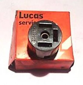
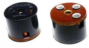 First 553738 type

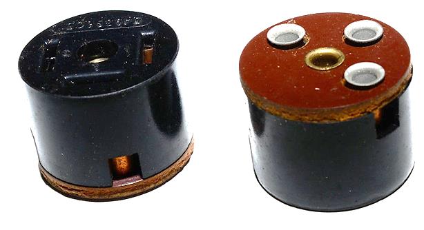

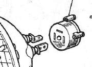 Second version of 553738
4. The PF700 and F700 range for Europe for XK140 and XK150
Differentiation is made in two groups of countries:
4.1. Continental Europe: “Le Mans 24” light unit for Switzerland, Holland, Norway, Sweden & Germany
XKs for Switzerland and Holland had special head lamps (Lucas 51565A), as well as those for Norway, Sweden and Germany (Lucas 51564A). These were all based on the so-called “Le Mans 24” light unit (Lucas 554665) and therefore used the same 1½” bulb holder and headlamp wiring loom (Lucas 858543), although the BPF bulbs were different (Lucas 370 with 45/40 Watt for the first group and Lucas 350 with 35/35 Watt for the second group of countries).
Bulb holder Lucas 858543 is an assembly consisting of bulb holder 556402 combined with 3 wires of suitable length for its application and a rubber grommet. It has been widely used for various brands in the 1950’s on PF770, PF700, F700 and other light units. Bulb holder assembly 858543 is intended for light units with a dipped beam and has 3 wires, whereas Bulb holder assembly 858540 is intended for non-dip beams and this loom has therefore one wire less than the aforementioned version
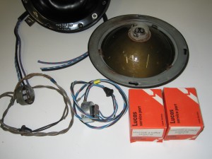 PF700 Le Mans headlights with Adaptor assy 858543 (left) and later replacement Lucas 54933718 (right)

4.2. Continental Europe: other countries with PF700 for XK140 and XK150
Some XK140 and XK150 versions intended for Continental Europe (except France, Switzerland, Holland, Norway, Sweden and Germany) used not a J700 but a PF700 type head lamp (51507A) with light unit Lucas part number 554917.
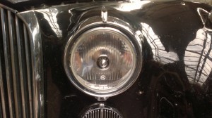 Lucas PF700 type 51507A with light unit 554917
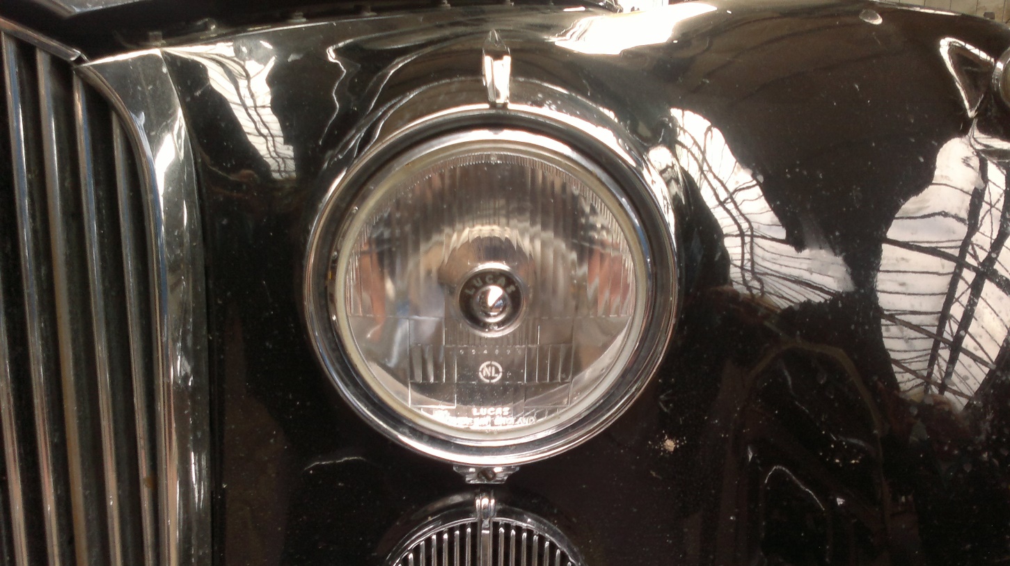
The corresponding bulb holder is Lucas 554602 for the 45/40 Watt BPF lamps Lucas 370. This adaptor is in fact a bulb holder supplied without wires. For the installation of the earth wire to this bulb holder the “Terminal Sleeves” Lucas 188818 were supplied as well. The light unit of this PF700 is related to the “Le Mans 24” unit and has the same adaptor opening of 1½” or 38 mm .

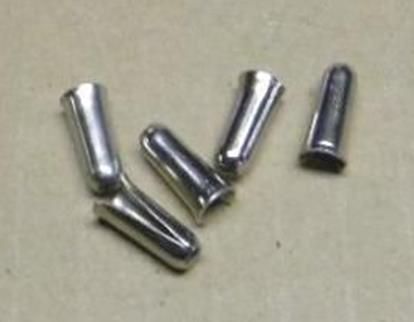
5. XK120, XK140 and XK150 for France
The French market required different Headlamps (Lucas 51563A) based on a 3-pin bulb BA21d lamp base (no BPF) and therefore also a different Bulb Holder / Adaptor (Lucas 562303). This solution was used over the entire existence of the XK range, although different light units have been applied.
 French bulb
The French light unit for the XK140 and 150 is a special version (Lucas 555288) of the standard “Le Mans 24” unit (554665) that we described in chapter 4.1. As Lucas bulb holder 562303 for the P45t bulb has a smaller diameter than the BPF 370 bulb of the standard “Le Mans 24” version, an additional “Shell Adaptor for Bulb” with Jaguar part number 6527 and Lucas 555943 is required.
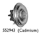 Special “french” Shell Adaptor Lucas 552943
6. Survey of XK bulb holders, shell adaptors and replacements
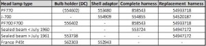
The Bulb holder assembly Lucas 858543 has been replaced by Lucas 54933718 which is a generic replacement for various brands.
 Can still be found…
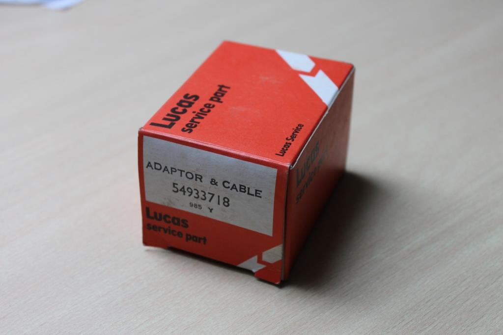
7. Bulb holder adaptors
To use BPF lamps on US cars (or European cars with a “non-BPF” headlamp loom) an adaptor exists that fits in the existing Lucas 553724 loom or the later Lucas 553738 bulb holder. This Adaptor has Lucas part number 554691

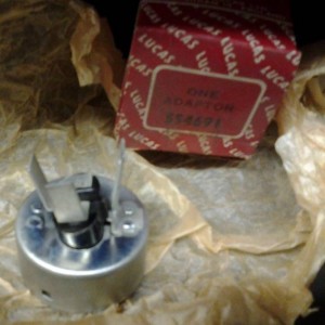 Front and rear of Lucas Adaptor 554691, converting e.g. US headlights looms to BPF bulbs
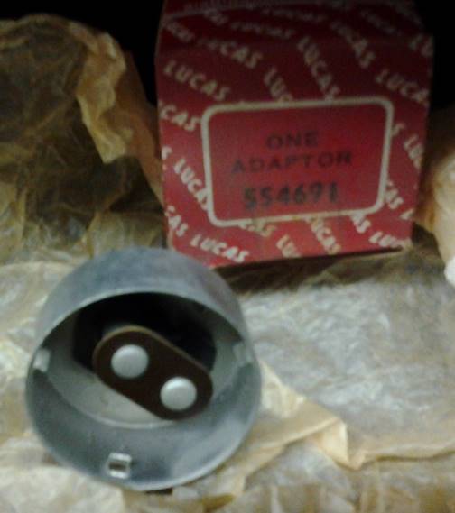

In the 1960s Sealed Beam headlamps were introduced in Europe; all sealed beams had the 3 pin connection whereas most British cars still had a BPF bulb holder. To facilitate the conversion to sealed beam lamps special adaptors were made with a 3 pin connection on one side and the BPF connection on the other side, fiting in the standard BPF headlamp harness with bulb holder. Note that these adaptors were also supplied by the (in those days British company) Osram-GEC in an attempt to increase the sales of these sealed beams. This is of course also a fine solution for British car owners in the USA who want to convert an existing BPF harness.
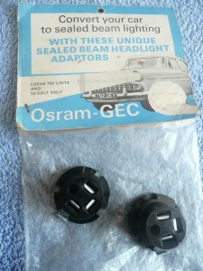 Adaptor for converting BPF harness to Sealed Beam lamps