Overview of Jaguar Chassis Plates used from 1946 to 1974
Jaguar used various types of Chassis (or Identification) Plates in the post WW2 period. The changes in dimension and lay-out of the plates were mostly the result of changes in available space when new models were introduced, but also due to changing brand names of lubricant suppliers or their respective products.
When focusing on the changes related to Chassis Plates we may conclude that the most apparent change relates to size and orientation of the plates in 1948. In the years before a smaller brass plate (Type A, 3½ x 4″) was vertically positioned containing relevant car data and accompanied by a similarly sized plate containing lubricant recommendations.
From the launch of the XK 120 in 1948 the plates were larger and had a “horizontal format” with both car data and lubricant recommendations combined on one plate. The initial size of this plate (Type B, 6½ x 4¼”) as used for the Jaguar Mk V, was apparently too large as it was reduced in October 1949 (Type C, 5¾ x 3¾”).
This then became the standard format for over a decade, with only a change-over from brass to aluminium in 1957.
| Type No |
Dimension |
Material |
Used on |
Year |
| TYPE A.1 |
3½ x 4″ |
brass |
Mk IV |
1946 |
| TYPE A.2 |
3½ x 4″ |
brass |
Mk IV |
– |
| TYPE A.3 |
3½ x 4″ |
brass |
Mk IV |
– |
| TYPE A.4 |
3½ x 4″ |
brass |
Mk IV and very early Mk V |
– |
| TYPE B.1 |
6½ x 4¼” |
brass |
Mk V, very early XK 120 |
1948 |
| TYPE C.1 |
5¾ x 3¾” |
brass |
XK 120 |
From October 1949 |
| TYPE C.2 |
5¾ x 3¾” |
brass |
XK 120 |
From March 1952 |
| TYPE C.3 |
5¾ x 3¾” |
brass |
XK 120 |
From August 1952 |
| TYPE C.4 |
5¾ x 3¾” |
brass |
XK 120/XK 140 Manual |
From October 1953 |
| TYPE C.5 |
5¾ x 3¾” |
brass |
XK 140 Auto |
1954 – 1957 |
| TYPE D.1 |
5¾ x 3¾” |
alu |
XK 150 Manual |
1957 – 1960 |
| TYPE D.2 |
5¾ x 3¾” |
alu |
XK 150 Auto |
1957 – 1960 |
| TYPE D.3 |
5¾ x 3¾” |
alu |
XK 140 Manual |
only 2nd half 1957 |
| TYPE D.4 |
5¾ x 3¾” |
alu |
4XK 150 Auto |
only 2nd half 1957 |
| TYPE E.1 |
6½ x 3¾“ |
alu |
|
1961? |
| TYPE E.2 |
6½ x 3¾“ |
alu |
|
|
| TYPE E.3 |
6½ x 3¾“ |
alu |
|
|
| TYPE E.4 |
6 ½ x 3¾“ |
alu |
|
|
| TYPE E.5 |
6 ½ x 3¾“ |
alu |
|
|
| TYPE E.6 |
6½ x 3¾“ |
alu |
|
|
| TYPE E.7 |
6½ x 3¾“ |
alu |
|
|
| TYPE E.8 |
6½ x 3¾“ |
alu |
|
|
| TYPE E.9 |
6½ x 3¾“ |
alu |
|
|
Type A plates on Jaguar Mk IV

 Type A4. (?)
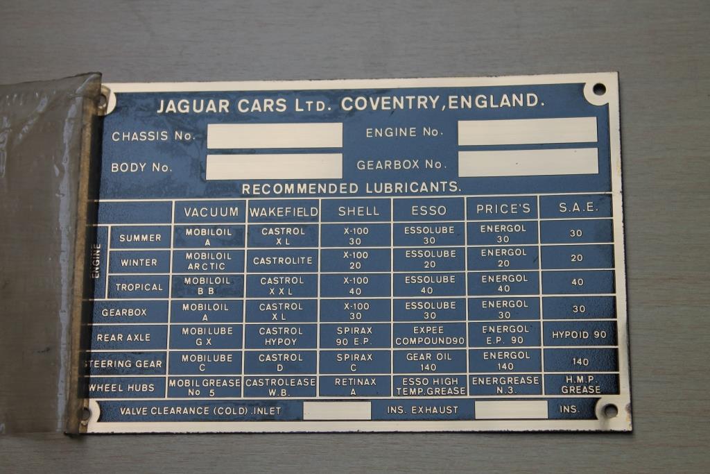
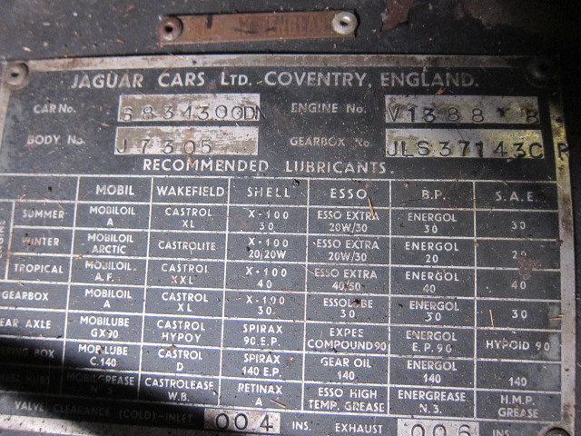
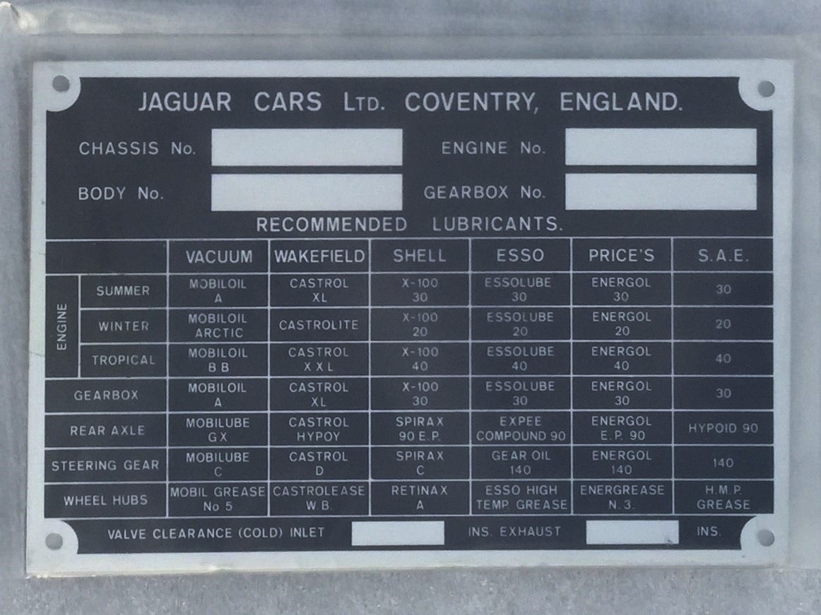
Type A plate on a 1948 Mk IV. Plate dimension: 3½ x 4″ . May also have been used on very early Mk V cars. Each of the 3 available engines had a specific plate. The lay-out shows only fields for CHASSIS No, ENGINE No and BODY No and is vertically oriented; all later plates have a horizontal orientation. There may have been 4 text variations for this plate (indicated with A1. to A4.) The recommendations for LUBRICANTS are shown on an identically sized plate next to the Chassis plate: VACUUM, WAKEFIELD, SHELL, ESSOLUBE and PRICE’S are mentioned here.

Type B plates on Jaguar Mk V
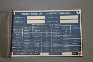
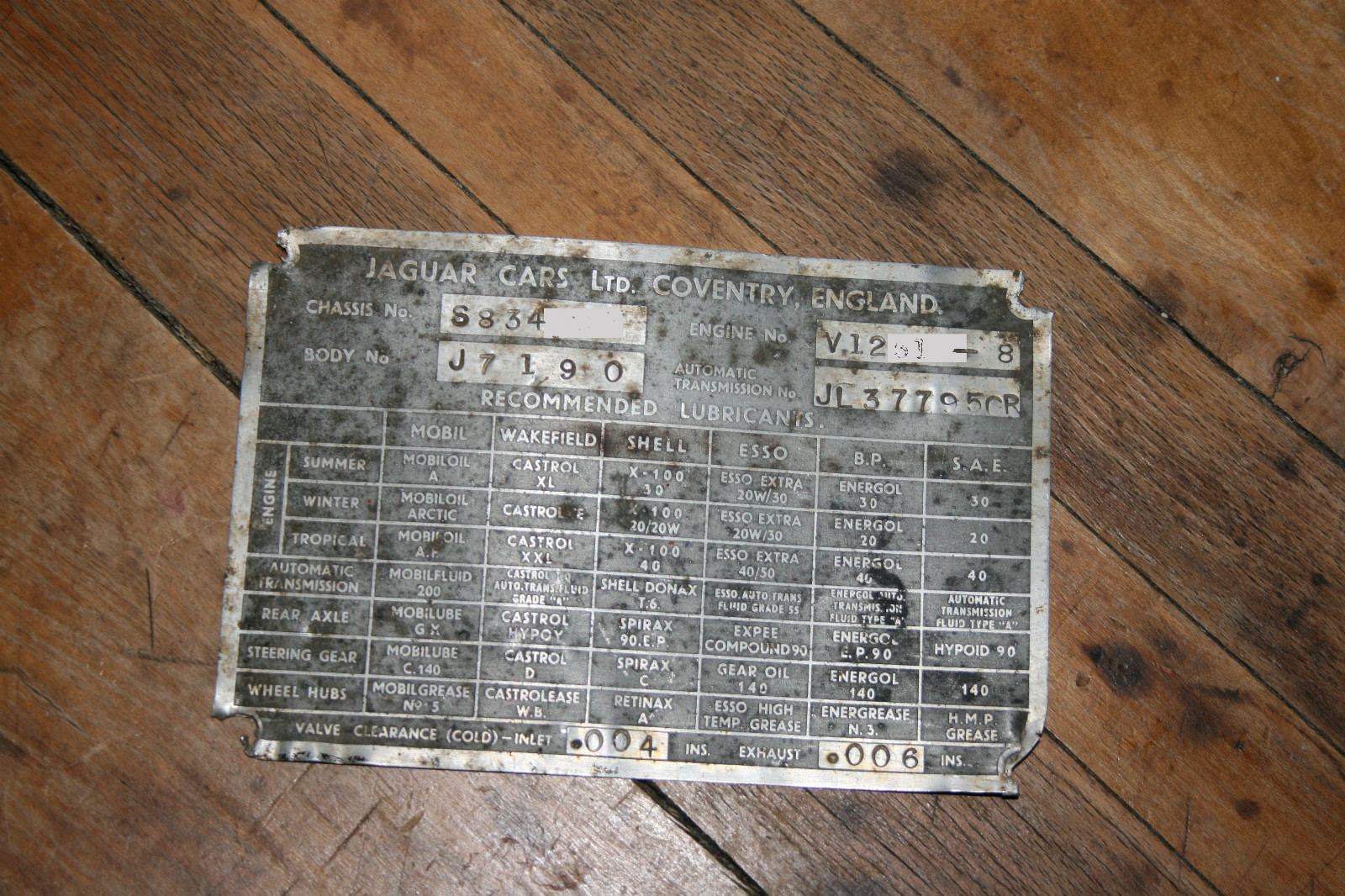
This new Chassis Plate measures 6½ x 4¼”, made of brass and plated with nickel. The lay-out has now 4 fields for CHASSIS No, BODY No, ENGINE No and GEARBOX No. The recommendations for LUBRICANTS remained unchanged: VACUUM, WAKEFIELD, SHELL, ESSOLUBE and PRICE’S, but an additional column has been added to show the S.A.E. viscosity. The recommendation from PRICE’S for the WHEEL HUBS was blank. To indicate the VALVE CLEARANCE two new fields have been created to be stamped per car type.
The overall lay-out was the basis for the later Type C plates.
Note: The Mk V manual contains one photo of a car with the smaller ID plate from the Mk IV era.
![clip_image002[4]](https://www.bobine.nl/jaguar/wp-content/uploads/2013/05/clip_image0024_thumb.jpg "clip_image002[4]") Type B1
Type B1
Type B plates on Jaguar XK 120 (very early examples)
See data under Mk V. The same plate (Type B1) was used for a number of early XK 120 OTS versions.
Type C plates on Jaguar XK 120
Type C plates were identical to Type B plates but smaller in dimension. Four different Identification plates have been used over the life of the XK 120: C1 to C 4 (with B1 as the fifth variation for the very first XK 120’s).
The first plate (Type C1) showed a blank box for Price’s recommendation for Wheel Hubs lubrication, as was the case with the Type B plate.
![clip_image002[6]](https://www.bobine.nl/jaguar/wp-content/uploads/2013/05/clip_image0026_thumb.jpg "clip_image002[6]") Type C1.
Type C1.
This was corrected with a temporary solution by riveting an “add-on” plate over the bottom two rows, now showing BELMOLINE H.M.P. on the empty space. This version (Type C2, see here under) lasted for about 6 months from March to August 1952.
![clip_image004[4]](https://www.bobine.nl/jaguar/wp-content/uploads/2013/05/clip_image0044_thumb.jpg "clip_image004[4]") Type C2.
Type C2.
In August 1952 the” add-on” plate was replaced by a new plate (Type C3) fully identical to the Type C1 plate but now with BELMOLINE H.M.P. on the former empty space .
![clip_image006[4]](https://www.bobine.nl/jaguar/wp-content/uploads/2013/05/clip_image0064_thumb.jpg "clip_image006[4]") Type C 3.
Type C 3.
Note: also the Jaguar C-type used Chassis Plate Type 3 (see below).
 C-type chassis plate
Final change in Type C plates on Jaguar XK 120 and 140.
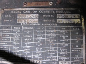
In October 1953 a number of modifications were made to the text of the Chassis Plate (Type C 4.). The most important modification was the change from ESSOLUBE to ESSO and BELMOLINE H.M.P. becoming now ENERGREASE No 3. These plates are otherwise easily recognisable by the text change in the VALVE CLEARANCE row, reading INLET and EXHAUST instead of the former abbreviations INL. and EXH..
 Type C4 (NOS!!)
Addition of “Automatic” Type C plates on Jaguar XK 140.
From January 1956 onwards an Automatic Transmission was offered for the XK 140, necessitating a change in the lay-out of the Plates. STEERING GEAR and WHEEL HUBS had been combined in one field and the lower row remained blank
 Type C5
Type D plates on Jaguar XK 150
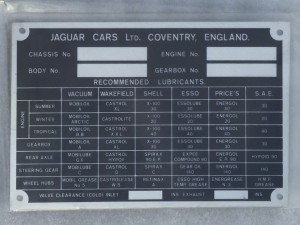
This type was introduced in 1957 on the XK 150 and was made of Aluminium instead of Brass as had been the material for all previous types.
The basic lay-out was in line with the Type C5 plates, meaning STEERING GEAR and WHEEL HUBS had been combined in one field and the lower row remained blank.
In addition some Lubricant suppliers had changed name as well as the names for oils and greases themselves. The changes were: MOBIL instead of VACUUM and B.P. instead of PRICE’S.
![clip_image002[8]](https://www.bobine.nl/jaguar/wp-content/uploads/2013/05/clip_image0028_thumb.jpg "clip_image002[8]") Type D1
Type D1
![clip_image004[6]](https://www.bobine.nl/jaguar/wp-content/uploads/2013/05/clip_image0046_thumb.jpg "clip_image004[6]") Type D2.
Type D2.
Plate for Automatic Transmission has same lay-out as Type C5 except for MOBIL and B.P.
 Type D3 with NOS version at the right
 Type D4
For a short period a few XK 150’s (without any logical sequence) manufactured from June to November 1957 had a different plate: the row for STEERING GEAR and WHEEL HUBS was no longer combined in one field and the bottom row was now in use. This for both manual (Type D3 plate) and automatic cars (Type D4 plate). It is unclear why this temporary solution had been implemented.
Type E plates on Jaguar E-type
Early E-Types continued the XK150 D style chassis plate. It’s not exactly clear when Jaguar switched over to a new plate but possibly the first 500 cars (with outside bonnet locks) may have carried the D type of chassis plate.
The chassis plate that followed for the E-type was a plate of larger dimension (6½ x 3¾“), which is about ¾ inch wider than the preceding types. The change-over to a larger plate may have been caused by the introduction of 7 rows for lubricant manufacturers instead of 5 plus 1 column for the SAE type of the lubricant. The new row reads: MOBIL. CASTROL, SHELL, ESSO, B.P., DUCKHAM, REGENT CALTEX TEXACO.
Note the little space between TEX and ACO on some plates.
![clip_image006[6]](https://www.bobine.nl/jaguar/wp-content/uploads/2013/05/clip_image0066_thumb.jpg "clip_image006[6]") 1966 E-type
1966 E-type

 12V SD 5 58.
 AUA 57 clone


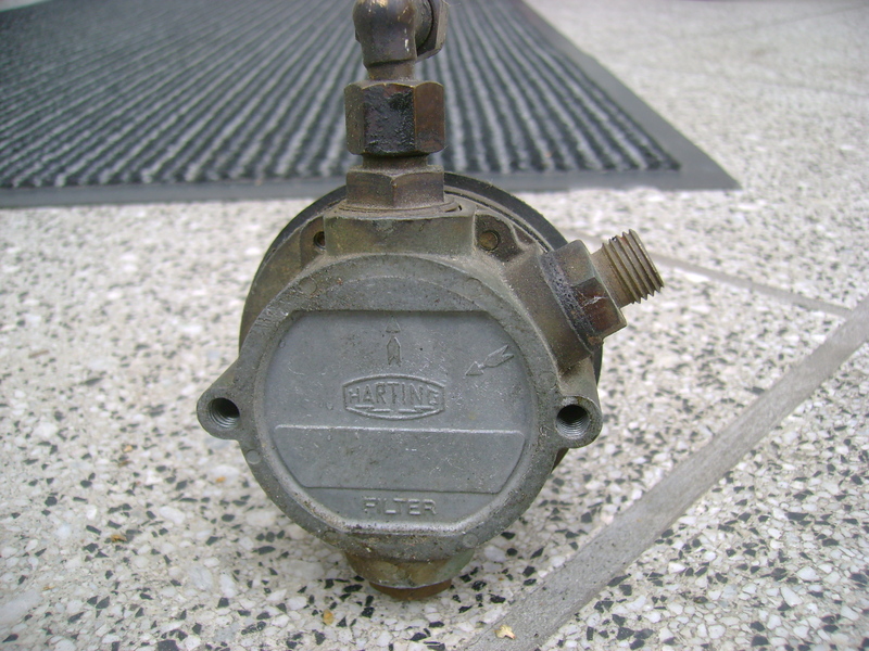
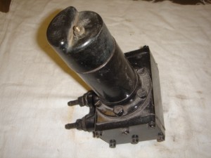
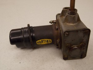
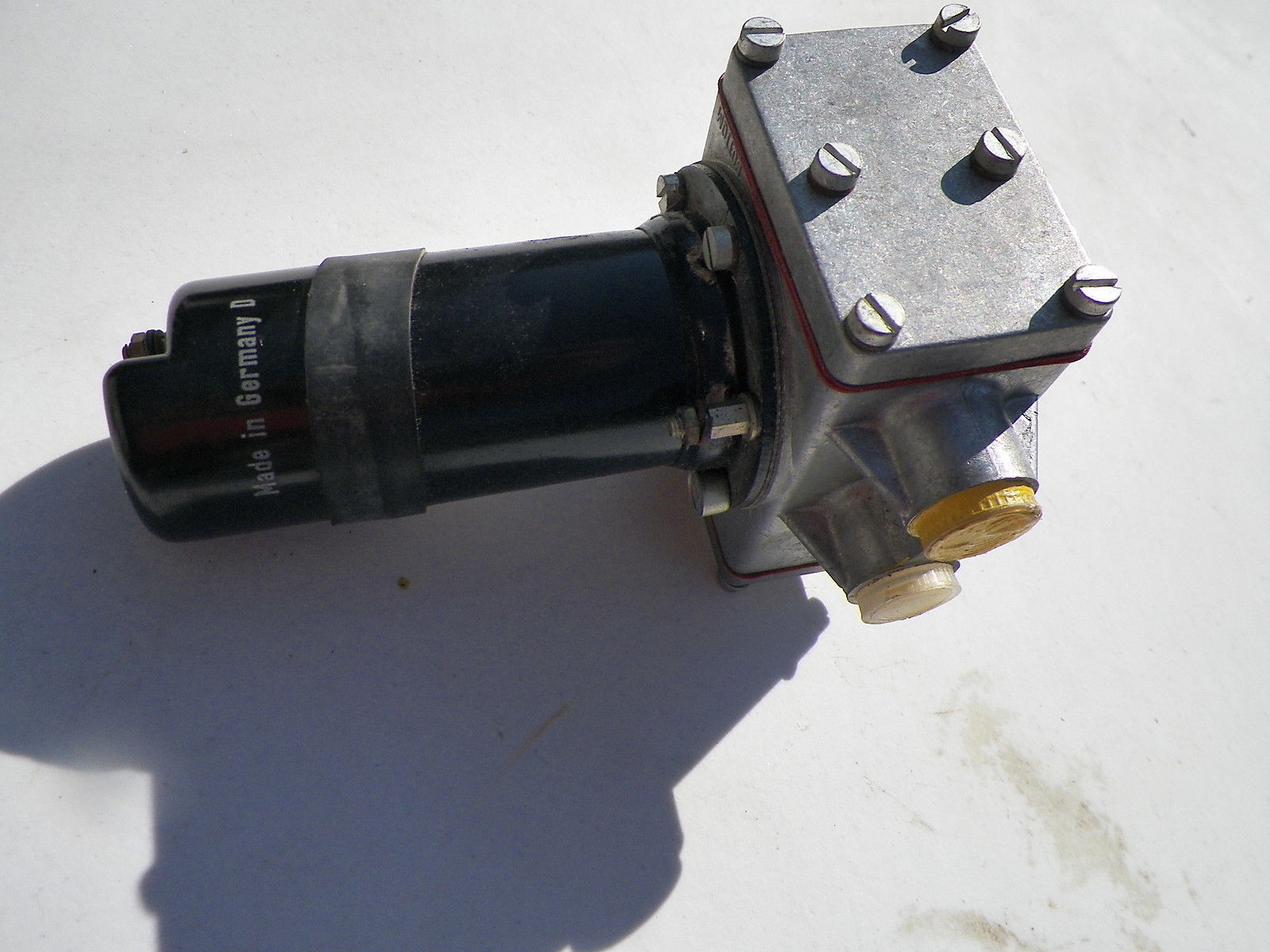
 NOS Harting pump
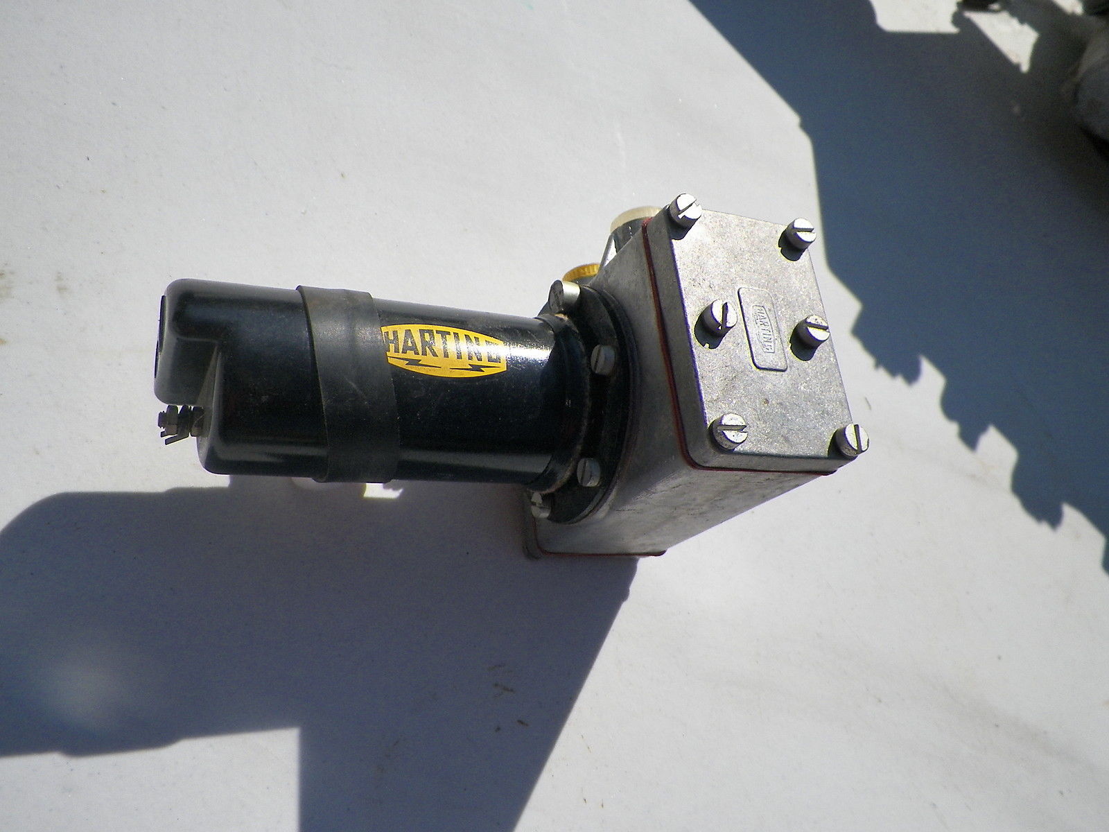

 Early version

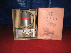
 Early version J 58 in original box
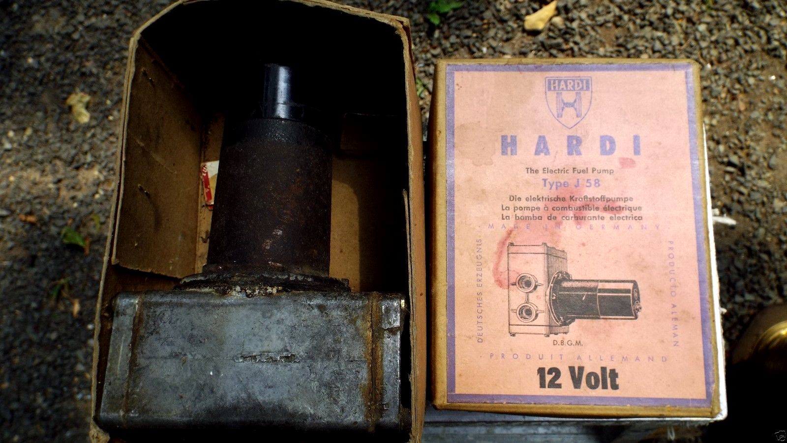
 1971 version

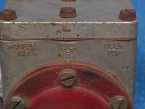
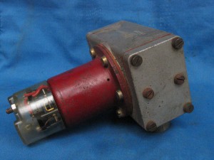
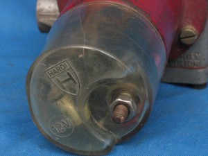
 Right: later Hardi type J58
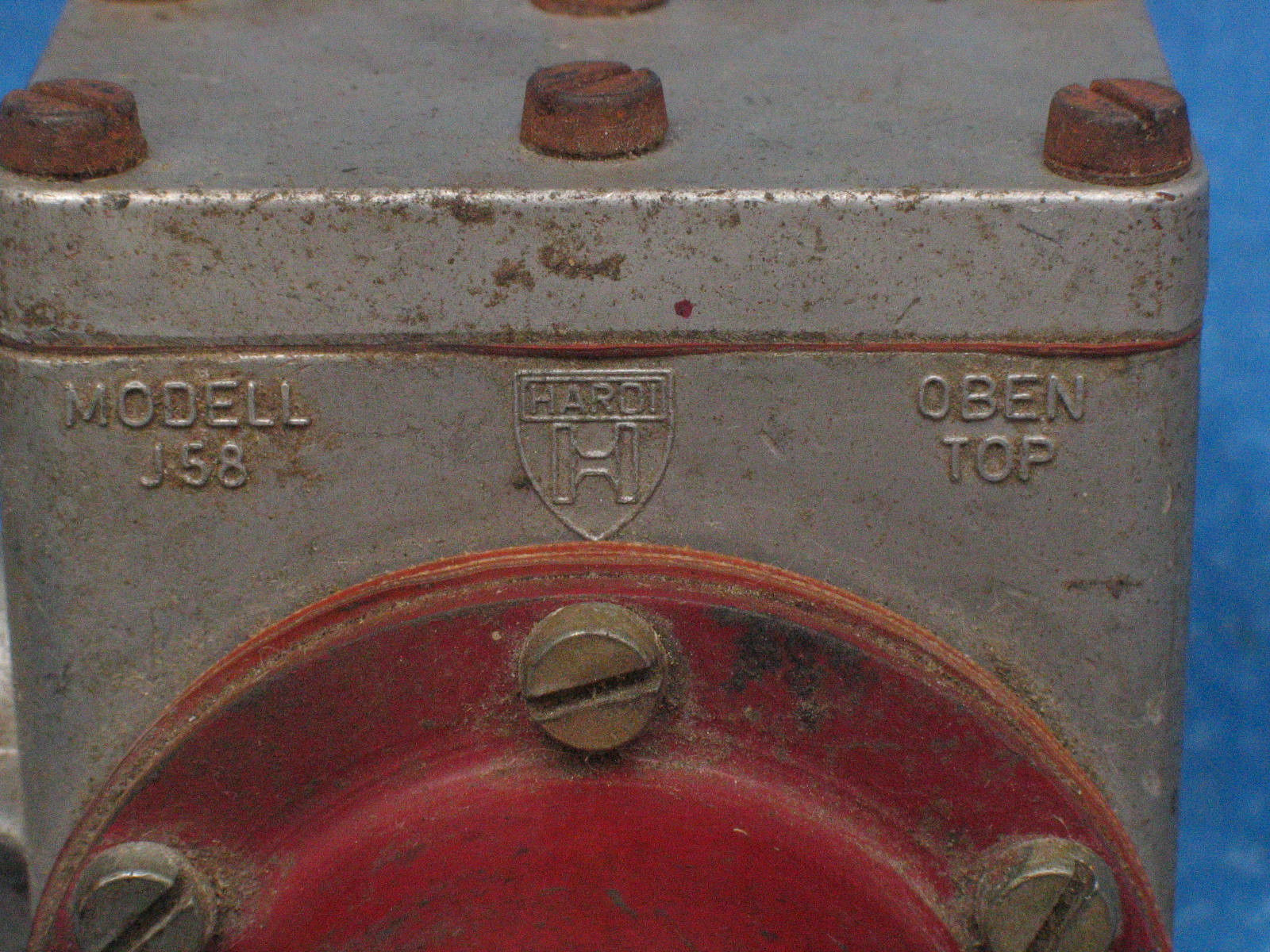


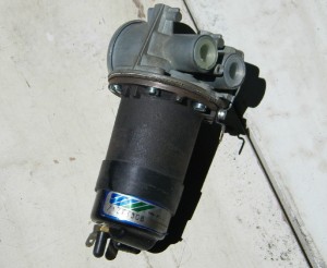
 Early version
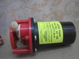
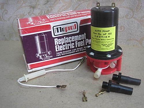
 Later version FP 500E

 Later FP 503E
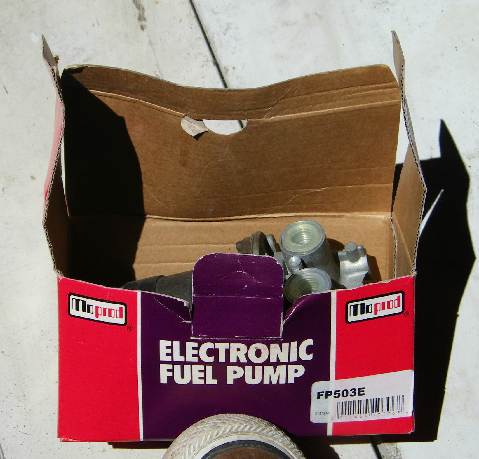
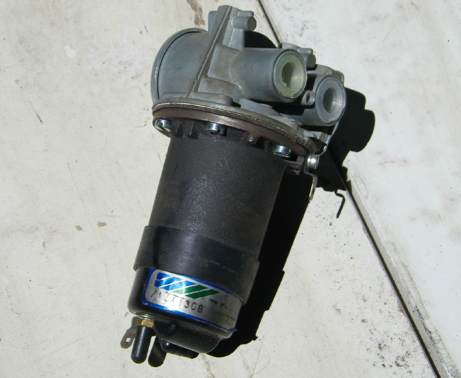

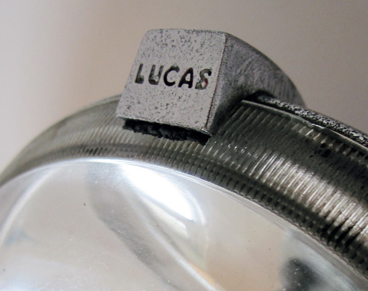
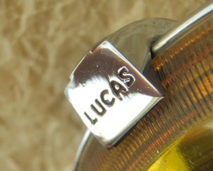 Early smooth top clamp (LH) and later ribbed top clamp (RH)


![clip_image002[4]](https://www.bobine.nl/jaguar/wp-content/uploads/2013/05/clip_image0024.gif "clip_image002[4]")
![clip_image002[6]](https://www.bobine.nl/jaguar/wp-content/uploads/2013/05/clip_image0026.gif "clip_image002[6]")


![clip_image002[4]](https://www.bobine.nl/jaguar/wp-content/uploads/2013/05/clip_image00241.jpg "clip_image002[4]")
![clip_image002[6]](https://www.bobine.nl/jaguar/wp-content/uploads/2013/05/clip_image00261.jpg "clip_image002[6]")
![clip_image002[8]](https://www.bobine.nl/jaguar/wp-content/uploads/2013/05/clip_image00281.jpg "clip_image002[8]")

![clip_image002[12]](https://www.bobine.nl/jaguar/wp-content/uploads/2013/05/clip_image00212.jpg "clip_image002[12]")
![clip_image004[4]](https://www.bobine.nl/jaguar/wp-content/uploads/2013/05/clip_image00441.jpg "clip_image004[4]")
![clip_image002[14]](https://www.bobine.nl/jaguar/wp-content/uploads/2013/05/clip_image00214.jpg "clip_image002[14]")
![clip_image004[6]](https://www.bobine.nl/jaguar/wp-content/uploads/2013/05/clip_image00461.jpg "clip_image004[6]")


![clip_image002[4]](https://www.bobine.nl/jaguar/wp-content/uploads/2013/05/clip_image0024.jpg "clip_image002[4]")
![clip_image002[6]](https://www.bobine.nl/jaguar/wp-content/uploads/2013/05/clip_image0026.jpg "clip_image002[6]")
![clip_image004[4]](https://www.bobine.nl/jaguar/wp-content/uploads/2013/05/clip_image0044.jpg "clip_image004[4]")
![clip_image006[4]](https://www.bobine.nl/jaguar/wp-content/uploads/2013/05/clip_image0064.jpg "clip_image006[4]")


![clip_image002[8]](https://www.bobine.nl/jaguar/wp-content/uploads/2013/05/clip_image0028.jpg "clip_image002[8]")
![clip_image004[6]](https://www.bobine.nl/jaguar/wp-content/uploads/2013/05/clip_image0046.jpg "clip_image004[6]")
![clip_image006[6]](https://www.bobine.nl/jaguar/wp-content/uploads/2013/05/clip_image0066.jpg "clip_image006[6]")