Introduction
 Complete DR1 wiper motor unit for XK 140

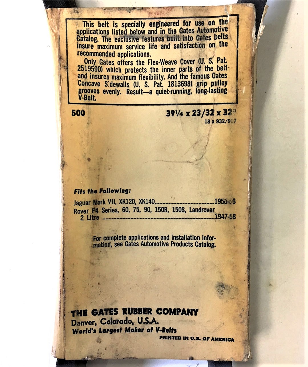
The Jaguar Mk VII was Jaguars first car to receive the new Lucas DR1 two speed motor in 1952 and the DR1 was used by Jaguar until 1957 when it was replaced by the DR3 type. Based on the experience gained from 1952 onwards all Jaguar XK 140 versions got this 2 speed Lucas DR1 type in 1954 and all have Jaguar Part Nº C11840 which is Lucas Part Nº 75233A. Next to the aforementioned Jaguar Mk VII also the jaguar Mk VIII in 1957 as well as the jaguar Mk1 2.4 litre saloon from 1956 onwards had a DR1 type wiper motor. Although in total 7 different Lucas DR1 motors have been used by Jaguar the wiper motor of the Jaguar XK 140 is unique as it is the only DR1 motor with a 90° wipe angle! Even if we include all 23 different Lucas DR1 motors supplied to different car manufacturers (see survey below) the DR1 motor for the XK 140 remains the only one with a 90° wipe angle.
 Survey of DR1 motors

So none of the other DR1 wiper motors are a direct replacement for the XK 140 and therefore be careful when purchasing a DR1 motor that has not the correct part number Lucas 75233. Unfortunately there are many sellers on the internet that automatically include the XK 140 in their list of applications when offering a particular (but wrong) DR1 motor. It is of course possible to replace the “Shaft and Gear” that determines the wipe angle (as we will see later) but finding a 90° version is “a needle in a haystack” as probably less than ten thousand have been made by Lucas ever.
A lot has been written about the Lucas DR1 wiper motor, the wiper loom and the required wiper switch types. Reference is made of the excellent story on the subject by Eric Capron presented on the Jag-lovers website http://www.jag-lovers.org/xk-lovers/library/wsmotor/motor.htm . But as all DR1 motors “as far as still alive” have fulfilled their duties for over 55 years, it is often required to thoroughly check the internals (or even to do a complete overhaul) to get it working again in a reliable way. And exactly this particular subject is not well documented. For that reason this article has been written, to learn about the mechanical aspects of this engine and about the problems you may encounter.
The DR1 construction
As the writer is far from an expert in electric motors, we will refrain from an in-depth electrical analysis of the motor and stick to the (electro) mechanical aspects. The Lucas DR1 wiper unit is a combination of a DC electro motor and gearbox in which a crank mechanism translates the high speed rotation of the motor in a low speed lengthwise movement of the wiper rack. The motor is of the “eccentric shunt” type, which stands for a motor with only one field coil situated on one side of the armature whereby the armature is positioned offset from the centre. The ‘ U ‘ shaped yoke of mild steel which forms part of the body of the unit completes the magnetic circuit, bringing the opposite polarity to the pole piece on the other side of the armature.
Disassembly
Disassembly starts by removing (if not already done when taking the wiper motor from the car) the aluminium cover from the commutator end bracket (one screw 2BA) after which the wires of the wiper loom become visible. There are 5 “push-in contacts” to which the individual wires have been connected and a special rectangular rubber grommet through which all 5 wires run. Try to save this one because they are difficult to find. The “End Cover Grommet” has Lucas part number 740722.
Note: a replacement “End Cover Grommet” Lucas 740722 is very difficult to find. The Aston Martin Feltham Club took the initiative to invest in a mould and remanufacture a small batch of these grommets in black poly-urethane and the grommet is also available to others. If you need one, contact the AMF Club on www.amfclub.com and look for Email in the RH column.

The DR1 Commutator End Bracket with 5 contacts, armature bearing housing and 2 through bolts
Now remove the 3 screws that hold the armature shaft bearing and the brushes and commutator will become visible. The complete end-bracket can be pulled outwards a bit after the 2 long through bolts (that connect end bracket, yoke and gearbox together) have been removed. The internal wiring is still attached and has to be removed with a soldering iron whereby the 5 lower contacts and the wires to the lower pivots of the brush gear have to be carefully removed. The brush gear can now be removed, but take care of the little spring in the middle and the two spring brackets that hold the ends of the spring ( see also the “exploded view”). Open the aluminium cover of the gearbox by removing the 4 screws. The crank is attached to the wiper rack at one end and to the gearwheel at the other end by means of a circlip that holds (resp.) a washer, a conically wound spring and a special washer. Remove the circlip but take care that it doesn’t get launched! Now the crank can be removed. Turn the gearbox + motor upside down and remove the circlip at the end of the gearwheel shaft: the gearwheel can be taken out from above. The armature can be removed via the open side of the Yoke. Remove the complete Yoke as well, noting the wire that runs from the Park switch through a hole in the gearbox and through the Yoke. The field coil and pole piece can be removed by unscrewing 2 screws at the underside of the Yoke. Access to these screws is located underneath the wiper motor rubber mounting Jaguar Part Nº 3556 and Lucas Part Nº 741583.
 XK 140 wiper motor rubber mounting

Also note the thermostatic switch which is riveted to the upper part of the yoke. It can be removed by drilling the rivet from the outside (3.0 mm drill) after which the assembly can be taken away from the inside. The Park (or end-) switch can be removed after the wire has been removed with a soldering iron. Unscrew and remove the cylindrical knurled adjusting nut at the end of the screw and lift the switch out of the gearbox. Save the spring over the adjusting screw.
Clean everything thoroughly: 60 year old grease contaminated with road dirt doesn’t help to create a “second life” for our wiper motor.
The motor parts further examined
The Lucas DR1 motor consists of the following main parts:
 Exploded view DR1 unit

- Yoke
- Field coil
- Armature & commutator
- Brushes
- Commutator end-bracket
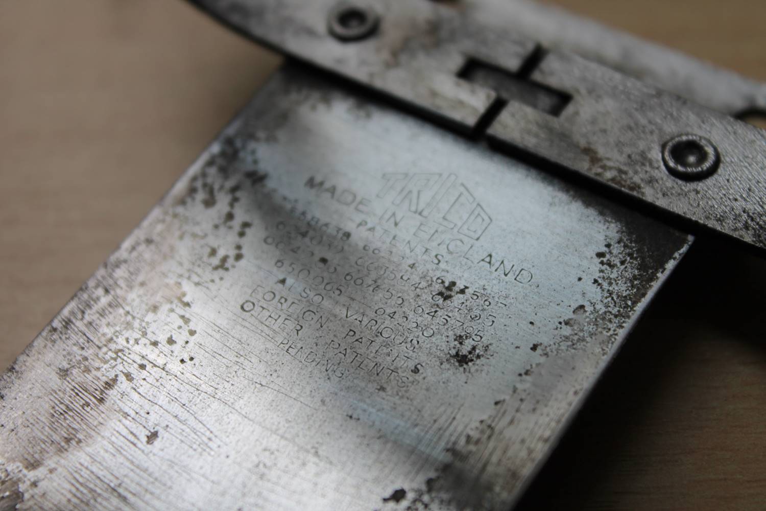
The yoke
The yoke has a typical U-shape with the field coil and pole piece mounted at the bottom and another pole piece at the (half cylindrical) top. On top of the Yoke the Lucas type plate is attached with 2 small rivets. In case it is required to repaint the Yoke it is possible to (carefully!) remove these rivets using a small screw driver. The Yoke originally had black wrinkle paint.
 Yoke with field coil and pole piece

The Lucas thermostatic cut-out switch.
The Lucas DR1 motor has a thermostatic cut-out switch to prevent any damage if the motor is excessively overloaded for whatever reason. This switch is wired in series with the armature and mounted on the inside of the yoke near the second pole-piece. It consists of a bi-metal strip and contacts, which open when the temperature rise increases a certain value and closes after the motor has cooled down. The thermostatic cut-out switch may have stopped functioning after many decades and is not available as a Lucas spare part. For the DR1 the cut-out switch will come in at about 135 to 150°C and closes again when the temperature has dropped to about 80°C.
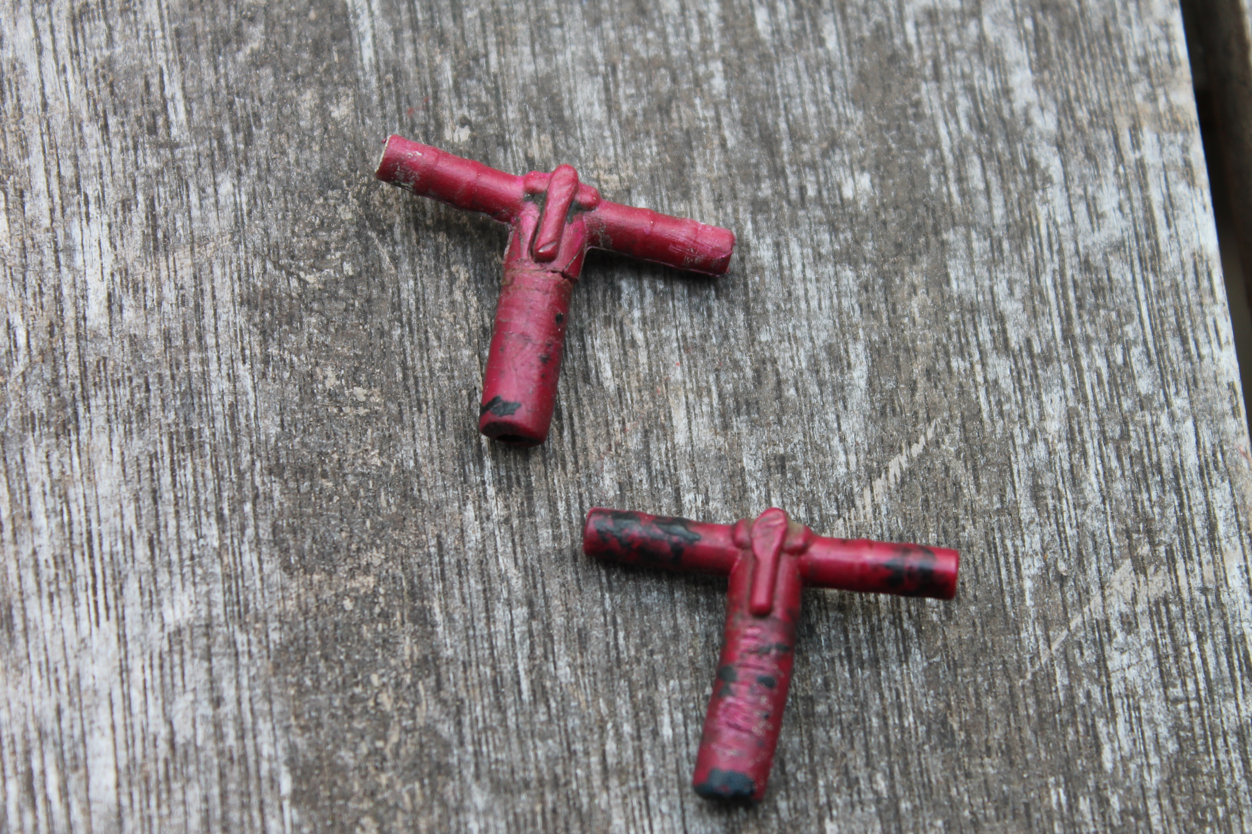
 Old (broken) thermostatic switch and modern replacement

A replacement Thermal Protector
These are miniature (15 x 7 x 3.5 mm) fully enclosed switches with a positive make and break action with a bimetal disc with a precise repeatable temperature performance over life (over 10k cycles). Various temperature settings are available. These switches have two 70 mm long wires that normally are sufficiently long to replace the wires of the old Lucas thermostatic cut-out switch. The one I chose for the DR1 is the version with a 140 ± 5°C temperature which resets at a temperature of 100 ± 15 °C. It is installed at the same spot as the original switch, but now using a small bracket that holds the thermal protector. It is sometimes easier to drill and tap a new thread (e.g. M4) instead of using the old copper rivet.
 Bracket to hold replacement Thermal Protector

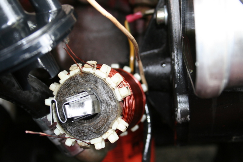
The field coil
The field coil consists in the case of a 2 speed motor type of two windings: (1) the field coil windings itself and (2) the additional resistance windings for the Fast speed status of the motor. The field coil and pole piece (which fits in the square centre hole of the field coil) is mounted to the Yoke with 2 countersunk 2BA x ½” screws from the underside.
 Field coil (Lucas Part Nº 740593) including pole piece

Field coil housing
The field coil housing has 3 wire connections (eyelets) in most schemes referred to as 1 – 2 – 3 from left to right:
- Connection 1: field windings and resistor windings start here
- Connection 2: field windings end here. Resistance of field coil about 8 Ω
- Connection 3: resistor windings end here. Resistance about 13 Ω

To check whether the field coil is still OK we can measure the following resistance values (all values ± 1 Ω):
- R 1-2 = 8 Ω,
- R 1-3 = 13 Ω,
- R 2-3 = 21 Ω
The thin copper wires from the two windings and the wiring to the rest of the wiper loom are soldered to the eyelets. Note that the field coil housing is made of a thermoplastic material that will melt if soldering takes (too) long!
Armature
The Armature and Commutator has Jaguar Part Nº C11840/3 and Lucas Part Nº 740616. Professional testing equipment is required to test the windings of the armature, but the condition of the commutator can be visually inspected. If burned or rough it can be lightly skimmed in a lathe after which the grooves have to be re-cut.
 Armature Lucas 740616

Commutator end-bracket
The Commutator end-bracket holds the armature brushes and the electrical contacts where the wiper motor loom from the wiper switch connects to the wiper motor: there are 5 terminals in total, numbered 1 to 5. The system of push-in connectors in which the wire ends are placed is difficult to install and rather unreliable over the years. An alternative solution is to solder the wires of the wiper loom directly to these terminals. For ease of (wiper motor) replacement it is then possible to cut the wiper loom 2 inches from the end and place double ended Lucas wire connectors and solder “bullets” to all 10 wire ends. We can use 5 individual connectors or the Lucas 5 pole connector Jaguar Part Nº 3570 and Lucas Part Nº 850832.
 Commutator end bracket with 5 terminals

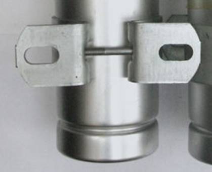
In addition the commutator end-bracket holds the armature shaft (brass) bush bearing which is self-adjusting, apart from the end-float of the armature shaft. The end-float is adjustable at the other end of the armature shaft in the gearbox. The screw and lock nut should be adjusted in such a way that the shaft can rotate freely with the smallest amount of end-float possible.
 Adjustable end-float of armature at left shaft end

The carbon Brushes can be replaced if necessary. The set of brushes has Jaguar Part Nº C11840/2 and Lucas Part Nº 729367 (later replaced by Lucas Part Nº 508170) and are identical for most Lucas wiper motors, measuring 5.2 x 5.2 x 8.2mm.
 Set of Brushes Lucas 729367

Re-wiring
Sometimes it is necessary to replace (some of) the internal wiring which may have become damaged or brittle. The best wire to use here should have a high degree of “flexibility” as we will have to “fold” various motor parts together during assembly. If the field coil is still OK, we can solder new short pieces of wiring to the eyelets numbers 1 to 3 and connect the other end of the wiring to terminals 1 to 3 of the Commutator end-bracket. (See drawing below). The wires of the thermostatic switch (or a new Thermal Protector) run from terminal number 5 to one of the brushes. Please note that (contrary to the Lucas drawing) I had to reverse the polarity of the two brushes (positions A en B) to get the motor running in the correct direction. So don’t take this (Lucas) drawing as the only official benchmark. In my case the return wire from the thermostatic switch runs to brush contact B (and not to A). The wire soldered to the other brush contact A is connected to terminal 4, to which also the wire from the Park switch is soldered.

“Official” Lucas wiring scheme; note that brush contacts A en B may have to be reversed
Rotation Directions in N, F and P
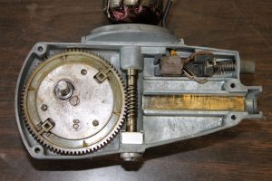
The large plastic gearwheel turns with the wiper switch in position N (normal) or F (fast) in a counter clockwise (CCW) direction if we look from above (Alu cover removed). In position P (park) the gearwheel should turn in the opposite direction, so clockwise (CW), in order to operate the park switch whereby the eccentric mechanism increases the stroke of the crank via a clever construction on the gearwheel.
Eccentric mechanism & Park Switch
A special mechanism on the gear wheel pin (to which the crank is fixed) secures that the crank stroke becomes longer when the gearwheel turns in a clockwise direction. The far end of the crank (or better the end of the wiper rack to which the crank is connected) can then operate the park switch and break the electrical circuit (stopping the motor) in the required “park” position. By moving the park switch with an adjustment screw fore and aft it is possible to choose the correct park positions with the wipers close to the lower windscreen rubber.


With the wiper switch in Normal or Fast the gearwheel turns in a counter-clockwise direction and the end of the crank cannot touch the park switch. So only by reversing the direction of the motor the park switch can be operated. Also note that the DR1 for the XK 140 has a wipe angle of 90° with the wiper switch in N or F, but the park position itself may be somewhat beyond the 90° angle.
When adjusting and looking for the correct wiper-arm position on the splined wheelbox spindle (e.g. after a total renovation) it is first of all advisable to put the wiper-arms in the upright position because otherwise the wiper blades may run over the windscreen rubber and get damaged. Some may also put the wiper switch in N and use the ignition switch (with key) to find the end positions of the wipers. But when thereafter the wiper switch is put in P, remember that the wiper may run further down the windscreen than has been found with the wiper switch in N!

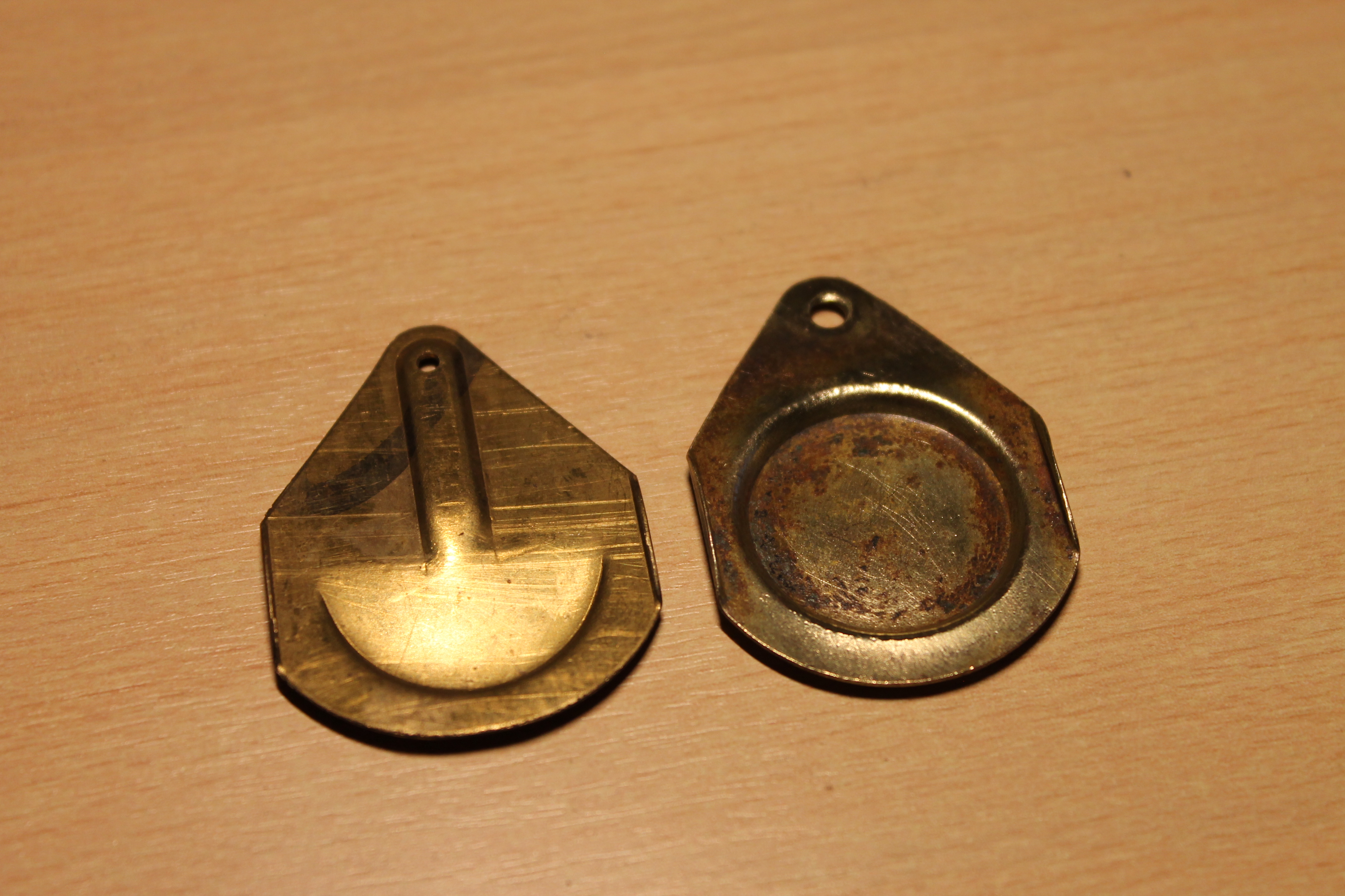
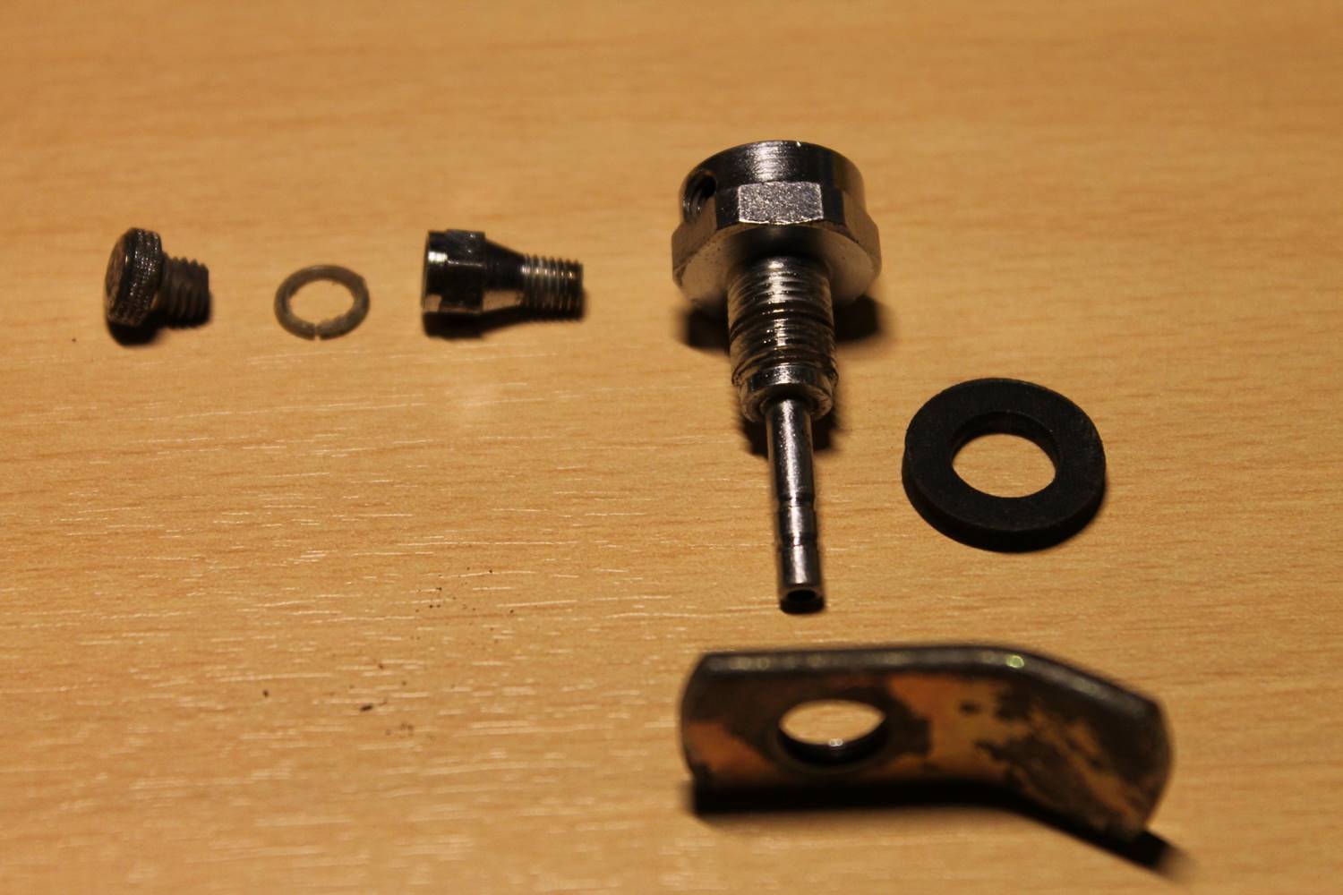
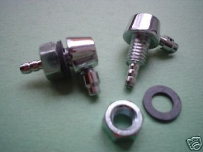
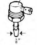
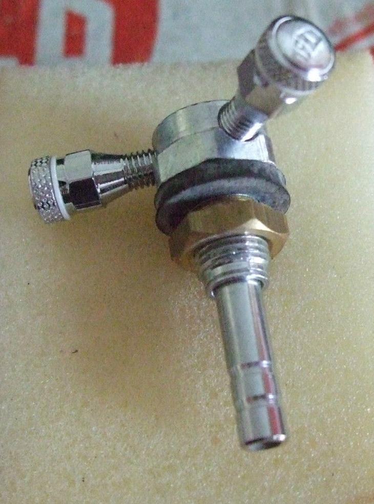
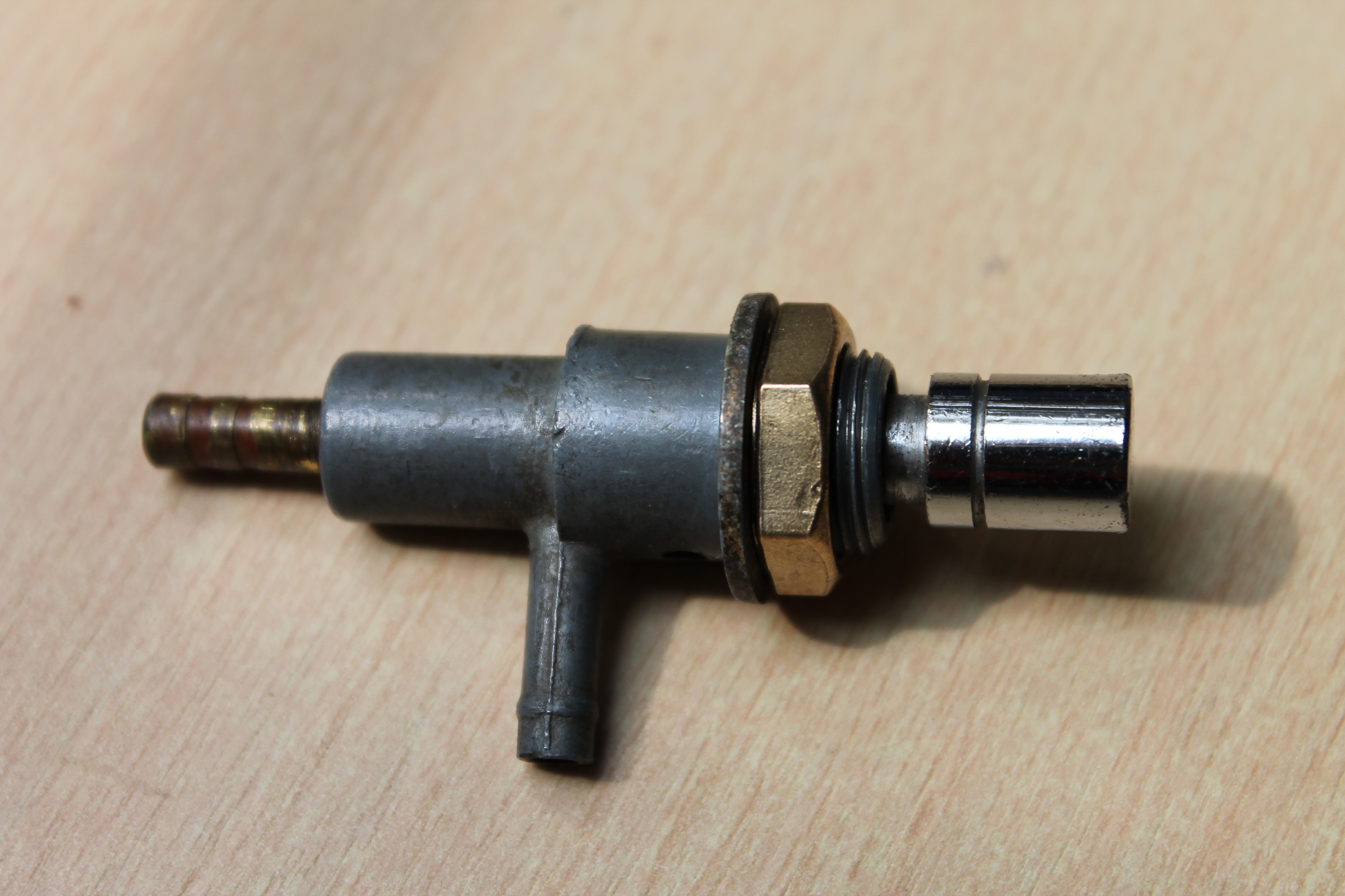
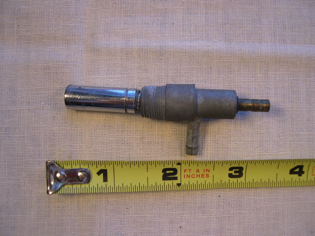
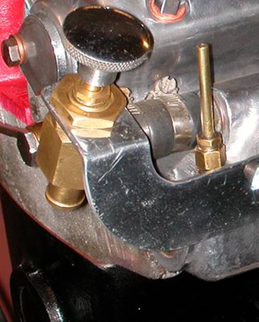
 Park switch components (Left) and in position (Right)

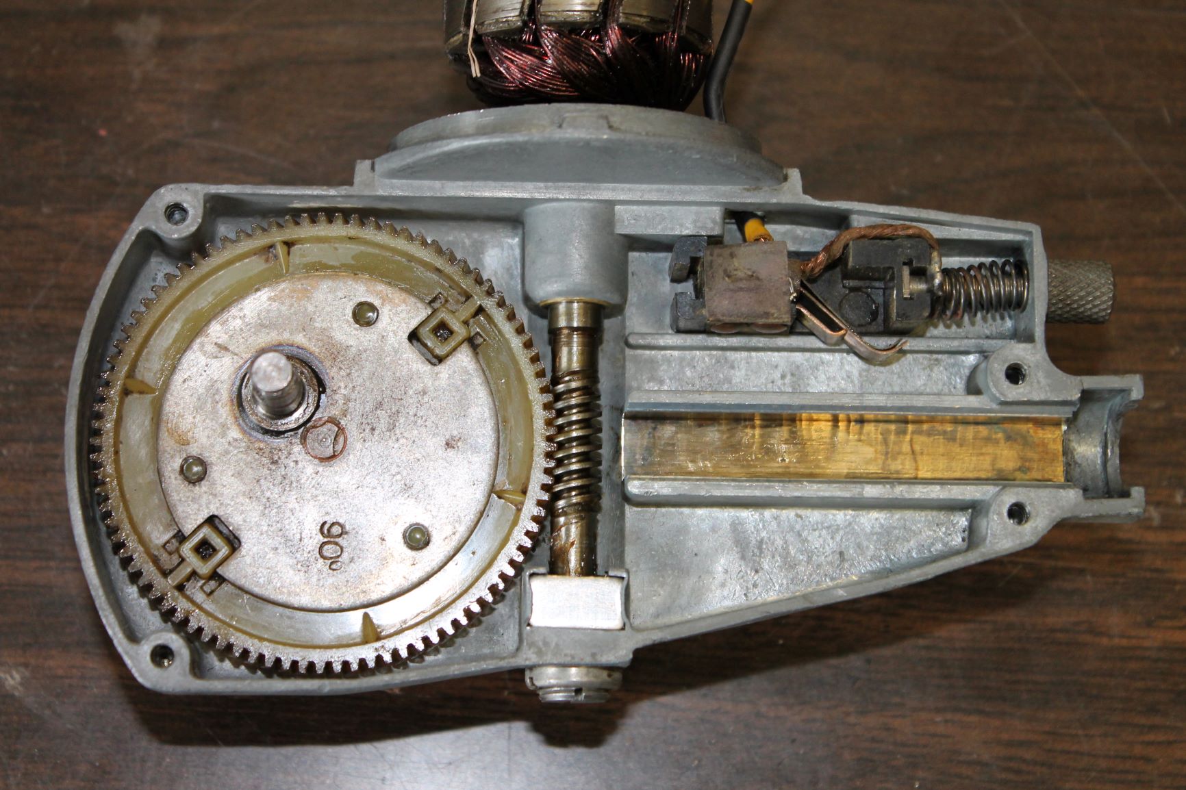
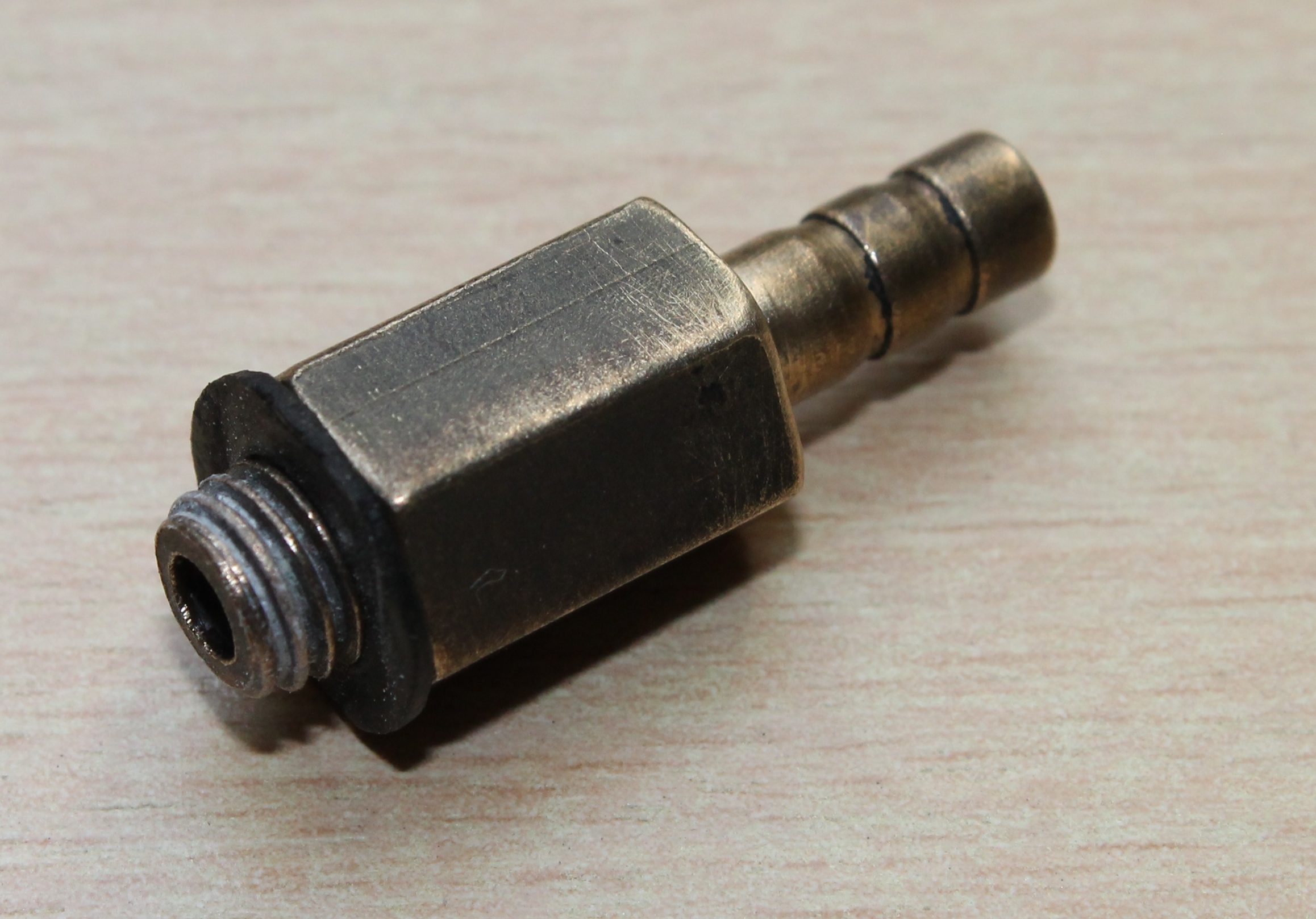
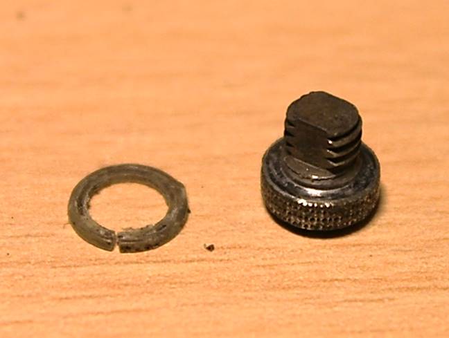
The adjustment mechanism of the park switch consists of a long screw with square head (that fits in the thermoset plastic housing of the switch), a long spring over the screw and a knurled nut on the outside of the gear box housing. Note the short earth wire with eyelet which is positioned over the screw between the spring and the plastic switch housing. Clean all these parts thoroughly or even add some tooth washers at both ends of the spring to secure a proper earth connection. After many years the spring may have lost some of its strength, meaning that the spring may not push the switch as far back as is sometimes required. It may help to pull and stretch the spring back to its original length or fit an appropriate replacement.
Installing the wiper motor in the car
It seems wise to first (bench) test the motor out of the car with a 12 Volt battery . Use the excellent schemes by Eric Capron presented on the Jag-lovers website (see chapter Introduction) for the basic connections. Test for all three positions (N, F and P) whether the gearwheel runs in the correct direction.
As the “striker” (that operates the park switch) is on the end of the wiper rack, it is not (yet) feasible to “bench” test the automatic park function, but if the switch contact is slightly depressed (with your finger for instance) the circuit is interrupted and the motor should stop immediately, if everything is wired correctly.
Installing the wiper motor in the car is a real challenge especially in case of the XK 140 FHC, as the motor is partly hidden underneath the LH wing (fender). For the OTS and DHC the position of the wiper motor is better accessable, but nevertheless the following information might be of use.
Placing the wiper rack, the crank, the components of the eccentric mechanism and finally the top cover (with 4 screws) is impossible with the motor in its final position (three holes for the rubber mounting). For the FHC it is easier to first place the motor away from the wing closer towards the engine, make all connections and place all parts first and only then postion the wiper motor in its final place. See the steps hereafter.
Use some grease on places where required (shafts, gearwheel, wiper rack head, eccentric mechanism, etc). It is recommended to pull the wiper rack a little out of the tubing (wiper arms removed from the spindles so they can turn freely!). Then place the crankpin in the wiper rack, taking care that the small bracket with the striker is on the side of the park switch. The other end of the crank fits over the pin on the gearwheel. First mount the special washer with the three “dents” on the crank (note the two flat sides of the pin), followed by the conical spring with a washer on top, and the circlip to secure the spring. This circlip is very difficult to place in particular in case of the FHC. I found it helpful to use a (self made) tool to press the spring and washer down while sliding the circlip in place. (See drawing).
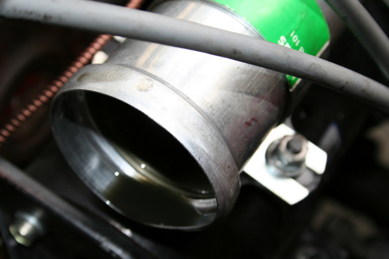
Then the wiper motor can be put in its final location by first pushing the wiper rack back in the tubing and installing the large tubing nut. Don’t forget to install the three nuts (and lockwashers) from the inside of the car to secure the wiper motor bracket studs.


![clip_image002[4]](https://www.bobine.nl/jaguar/wp-content/uploads/2014/05/clip_image0024.gif "clip_image002[4]")
![clip_image002[6]](https://www.bobine.nl/jaguar/wp-content/uploads/2014/05/clip_image0026.gif "clip_image002[6]")


![clip_image002[4]](https://www.bobine.nl/jaguar/wp-content/uploads/2014/01/clip_image0024.jpg "clip_image002[4]")