Category Archives: 15. Optional extras
Radiomobile radios for Jaguars (1948 to1961)
1 Reply
Radiomobile radios for Jaguar’s (1948 – 1961)
(Click pictures to enlarge)
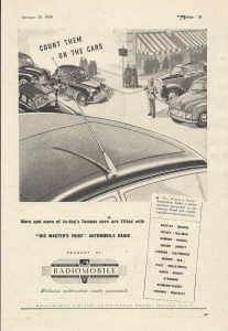
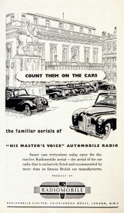
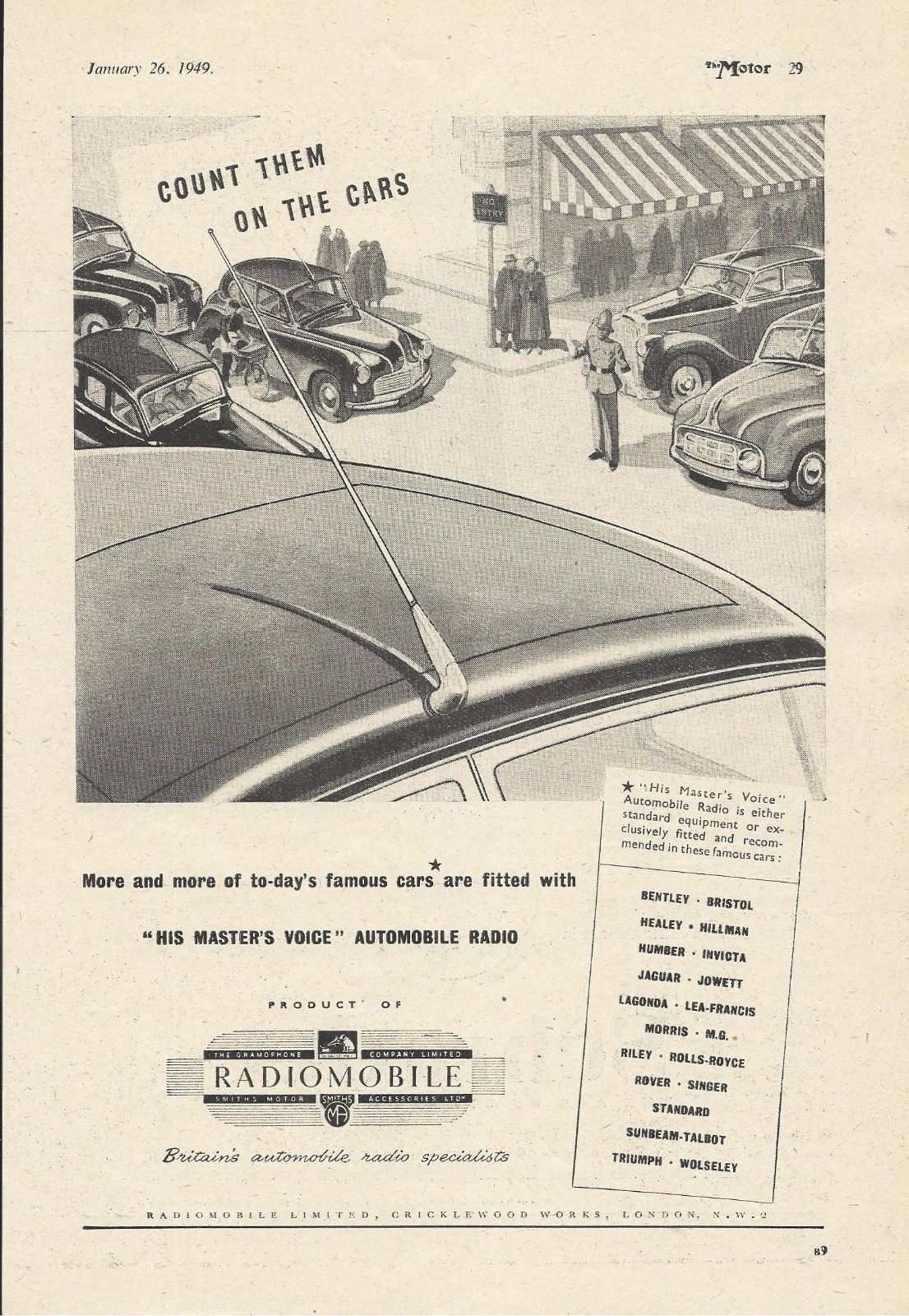
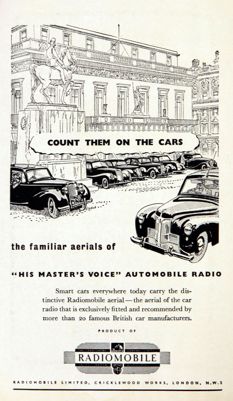
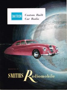
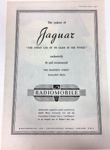
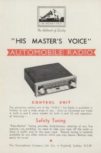
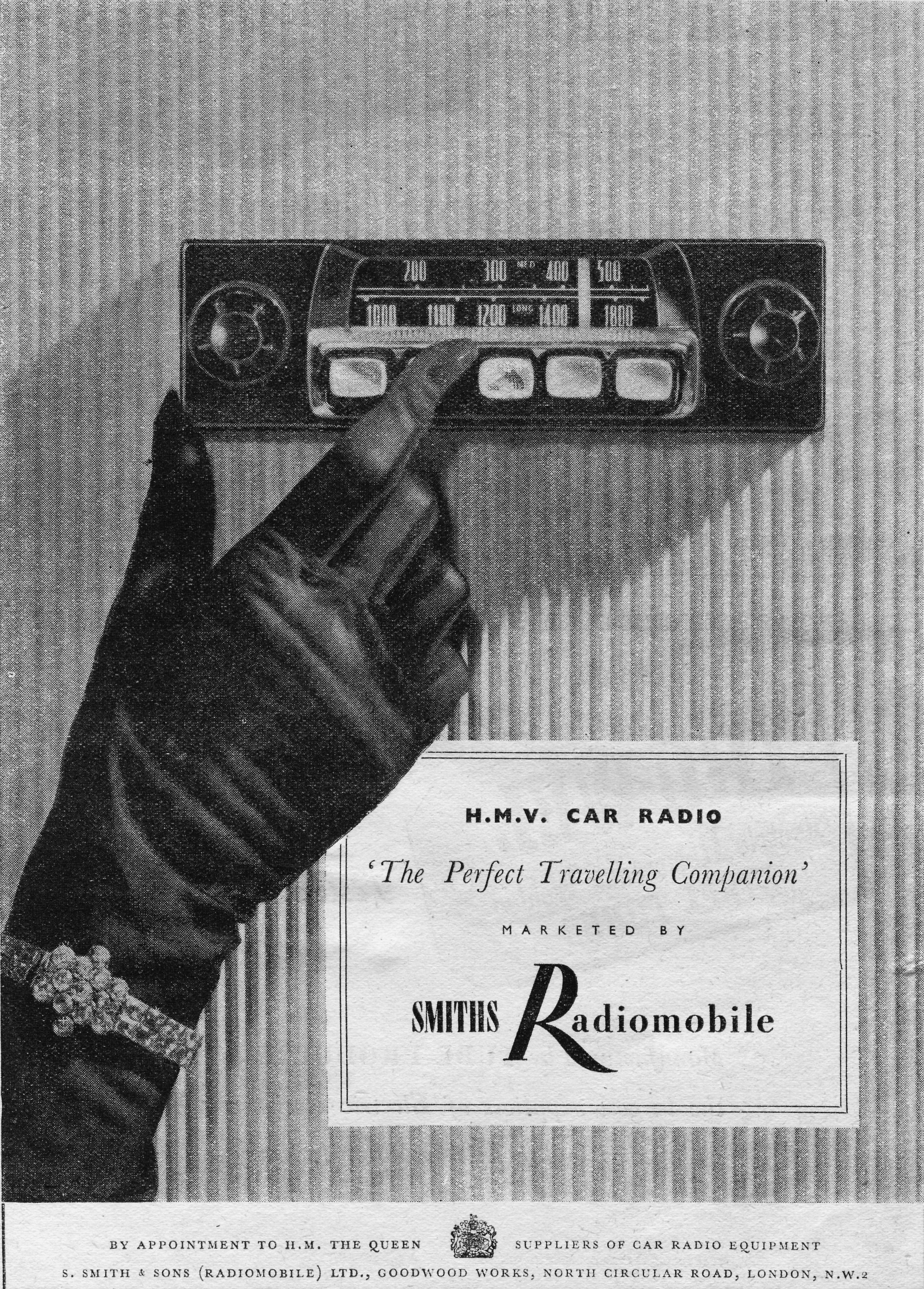
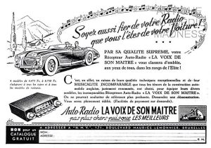
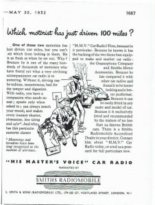 Early advertisements from 1949 to 1952

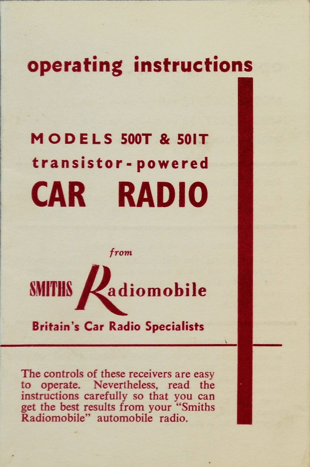
1. Introduction
After the war, Jaguar offered Radiomobile car radio systems as an “Optional Extra”. This article gives the history of the Radiomobile company and describes the radio systems fitted on Jaguar XK’s. As this survey started in the “pre-semiconductor” era, radio equipment used valves requiring a separate high voltage supply (over 200V!) placed in a box that was normally larger in size than the receiver unit itself. From about 1958 the first “transistorised” car radios appeared and miniaturization of equipment was about to start. We have to understand that these first transistor radios were in fact “hybrids” using a combination of valves and semi-conductors using a “semi-conductor” rectifier system and later some transistors.
We follow the development of the radios as used for the Jaguar XK 120, 140 and 150 over a period from 1949 till about 1961, but it is evident that the content also applies to contemporary Jaguar Saloon models.
 The new official Radiomobile logo (left) showed the two parent companies HMV and Smiths Motor Accessories. The HMV logo (right) was shown on many Radiomobile models.
1.1 The Radiomobile company
Electric and Musical Industries (EMI) had been established in 1931 in the UK as the result of a merger between The Gramophone Company and The Columbia Graphophone Company. Next to recording and playing equipment, also radar and television were the outcome of extensive research activities within EMI. Radio manufacturing became one of their key businesses.
In 1945 EMI and Smiths Motor Accessories Ltd. established a new company named S. Smith and Sons Radiomobile Ltd. (with offices at Great Portland Street, London W1) essentially to sell car radios, initially manufactured and developed by The Gramophone Company, part of the EMI group.
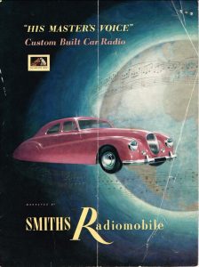
 Compare the 1953 brochures for UK (left) and USA (right): HMV name and logo removed due the rights of RCA in the US. Pictures Roger Payne


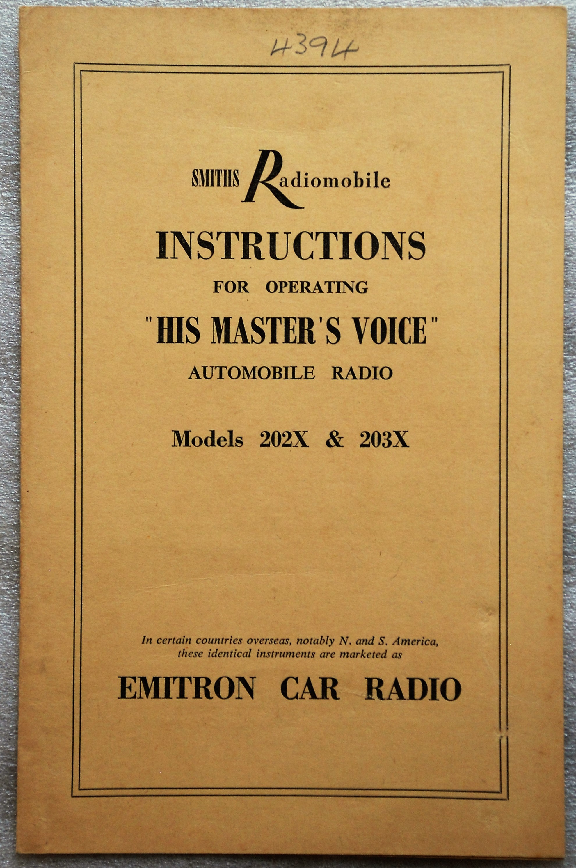
It was the intention of Radiomobile to use the His Master’s Voice brand name and call their radios HMV Car Radios and many radios therefore show the HMV name and/or emblem.
However, RCA in the USA still had the rights on the brand name His Master’s Voice for North and South America after they sold their share in EMI in 1935. It was thus not possible for Radiomobile to use the HMV brand name in the USA. Radiomobile radios fitted by Jaguar during production as an “Optional Extra” on cars destined for the USA were probably still branded as such with sometimes the HMV logo on the push-buttons. If a Radiomobile radio was fitted as an aftermarket product in the USA, these units were sold under the brand EMITRON. This brand name was owned and used by EMI for radio (component) exports to North & South America; EMITRON was also the brand name for radio valves and other electrical components manufactured by EMI and sold in the USA.
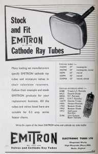 EMITRON as brand name for radio components

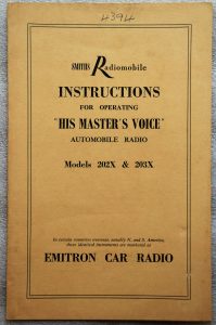
The official Smiths statement in their catalogues and brochures regarding this issue was: “In certain countries overseas, notably N. and S. America, these identical instruments are marketed as EMITRON CAR RADIO”. However, it seems that with the 1955 introduced 200 series the Emitron name had been dropped and all US destined versions were from now on Radiomobile branded, whereas in Europe (including UK) the two names (Radiomobile and His Master’s Voice) were used next to each other: the His Master’s Voice versions for the “high end” models only. The HMV brand name was eventually dropped in 1962 with the introduction of the 600 series, which only existed as a Radiomobile version throughout the world.
1.2 A survey of Radiomobile types from 1948 to 1961 as fitted on Jaguars
After the war the newly established Radiomobile company started the development and manufacturing of car radios. The following survey of 12 Volt Radiomobile car radios (using radio valves) should be seen as guidance only, as the precise dates of introduction of the various versions are often unknown, and radios still in stock may have been used in the Jaguar production of successor models. The application of models listed in Bold have been confirmed as “Optional Extras” in one or more Jaguar Spare Parts Catalogues.
- 1946 – 1951 100 Long & Medium Wave for Europe
- 1946 – 1951 101 Long & Medium Wave for Europe (no Tone Control)
- 1948 – 1951 4012 Medium Wave for N. & S. America and S. Europe
- 1948 – 1951 4014 Medium Wave for Australia & New Zealand
- 1949 – 1951 4050 Long & Medium & Short Wave for Rest of World
- 1951 – 1955 4100 Long & Medium Wave for Europe
- 1951 – 1955 4102 Long & Medium Wave for World excl. Europe
- 1951 – 1954 4200 Long & Medium Wave for Europe
- 1951 – 1954 4202 Long & Medium Wave for World excl. Europe
- 1953 – 1955 4260 Long & Medium Wave for Europe
- 1953 – 1955 4262 Long & Medium Wave for World excl. Europe
- 1953 – 1955 4263 As 4262 but 6 Volts
- 1953 – 1955 4300 Long & Medium & Short Wave for World excl. N.A. and Europe
- 1955 – 1958 200 X Long & Medium Wave for Europe
- 1955 – 1958 202 X Medium Wave for World excl. Europe
- 1955 – 1956 220 X Medium Wave for Europe
- 1955 – 1958 230 R Medium & Short Wave for World excl. N.A. and Europe
- 1956 – 1958 20 X Long & Medium Wave for Europe
- 1956 – 1958 22 X Medium Wave for Europe
- 1959 – 1961 40T Long & Medium Wave for Europe
- 1959 – 1961 41T Long & Medium Wave for Europe; polarity switch
- 1959 – 1961 42T Medium Wave for World excl. Europe; polarity switch
- 1959 – 1961 42TC Medium Wave for World excl. Europe; polarity switch; tone control
- 1959 – 1961 400T Long & Medium Wave for Europe
- 1959 – 1961 401T Long & Medium Wave for Europe; polarity switch
- 1959 – 1961 402T Medium Wave for World excl. Europe; polarity switch
- 1960 – 1961 50T Long & Medium Wave for Europe
- 1960 – 1961 51T Long & Medium Wave for Europe; polarity switch
- 1960 – 1961 52T Medium Wave for World excl. Europe; polarity switch
- 1960 – 1961 52TC Medium Wave for World excl. Europe; polarity switch; tone control
- 1960 – 1961 500T Long & Medium Wave for Europe
- 1960 – 1961 501T Long & Medium Wave for Europe; polarity switch
- 1960 – 1961 502T Medium Wave for World excl. Europe; polarity switch
We occasionally see an original Jaguar with a Radiomobile radio that is not on the official list of “Optional Extras” as listed in the various SPC’s. Remember that Radiomobile radios were also supplied and installed by Jaguar dealers afterwards. We mention e.g. the Radiomobile Model 4100 on the XK 120 and the Model 20X models used on the XK 150, which both were of a simpler design and may have been installed by dealers to save cost. For the latter, these models have been even included in the “Smiths Radiomobile Installation Instructions” for the Jaguar XK150. We have therefore included the description of several Radiomobile radios not formally recommended by Jaguar in this article.
When a radio was fitted by the Jaguar factory, a Radiomobile Operating Instruction folder and the Radiomobile Warranty card were included which had the Jaguars body number written on it in pencil.
1.3 Manufacturing facilities
From the early Thirties onwards HMV radio production was centred at EMI’s Sheraton Works in Hayes, 15 miles to the west of London. Radiomobile production of (HMV) car radios started in the existing Smiths Cricklewood Works, London NW2, a vast industrial site built in the 1920’s and continuously extended in the decades thereafter, housing various Smiths industrial activities including “Motor Accessories”. However, there are indications that the first HMV/Radiomobile car radios (100 series) have still been produced at Hayes.
The Cricklewood Works housed next to the Motor Accessories division three other Smiths activities: Industrial Instruments, Aircraft Instruments and the (well known) English Clocks production.
From about 1952 the production of car radios gradually moved to the new Smiths Goodwood Works, North Circular Road (Staples Corner) in London NW2, not far from the Cricklewood Works. The export division of Radiomobile stayed at Cricklewood, as we may conclude from various brochures.
2. Radio installations offered for the XK 120
2.1 Available “optional extras”
The following radios of the above listing were available for the XK 120 either as an “Optional Extras” over the period 1949–1954 or as a “dealer option”. The “Optional Extras” as listed by Jaguar have been indicated in Bold letters.
- Model 100 with Long and Medium Wave and Tone Control
- Model 101 with Long and Medium Wave, without Tone Control
- Model 4012 with Medium Wave for North and South America
- Model 4014 with Medium Wave for Australia and New Zealand
- Model 4050 with Medium and Short Wave
- Model 4100 with Long and Medium Wave
- Model 4102 with Medium Wave
- Model 4200 with Long and Medium Wave
- Model 4202 with Medium Wave
- Model 4300 with Long, Medium and Short Wave
Note that the 100 and 4000 series both had a “single unit” construction consisting of a receiver (also called controller), a loudspeaker and a power supply (or amplifier) although the latter could be detached. Later generations starting with the 4100 / 4200 / 4300 series, were of the “3 unit” construction” (or also called the “Electrical Link” construction by Radiomobile): receiver in/under the dashboard and both speaker and amplifier remotely positioned either in the front or the rear of the car all connected (“linked”) via electrical cables.
2.2 Model 100 (1948 – 1951)
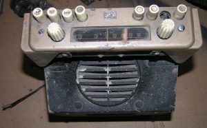
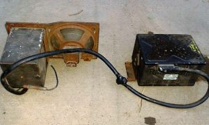
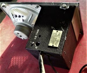
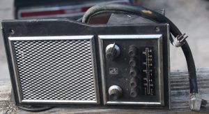
The first Radiomobile car radio was named Model 100 (manufactured from 1946-1951) and Jaguar initially used it from 1946 to 1948 in the 1½, 2½ and 3½ Litre Saloons. The Model 100 was only installed (as an option) on the OTS version of the XK 120. This Medium and Long Wave receiver was of the “single unit” construction. It received Jaguar part number C.4600. At the back of the receiver an amplifier unit was mounted (part number C.4601; Radiomobile code unknown) and connected via an external cable. The power output of this radio was 3.5 Watts and the 5” loudspeaker had an impedance of 5 Ohms. Normally the 100 was delivered in black (example shown below) but other colours for the front (escutcheon) were possible.
 Model 100 with its typical “single unit” construction, but the Amplifier at the back could be detached

Radiomobile supplied various colour combinations to the car industry to match e.g. the dashboard design. Radiomobile provided Bentley even with a wooden facia and a different scale. Note that the Jaguar versions for the 100 series were black (front and knobs) while other car manufacturers may have opted for other colours, knobs and scales.

 Bentley with wooden front Grey front and white knobs Beige front and white knobs


Radiomobile started to export these models throughout Europe in the early 1950’s.
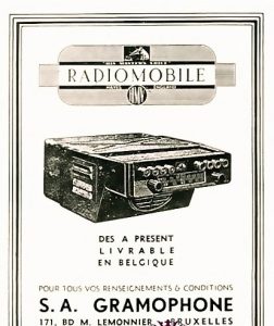 October 1948 Radiomobile advertisement for Jaguar Export: Belgian advertisement of RM 100


Model 101 was identical to the 100 but was supplied without Tone control and pre-set push buttons. This version was not in the Jaguar “Optional Extras” programme, but may have been installed by Jaguar dealers.
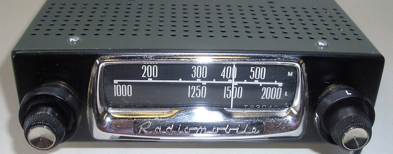
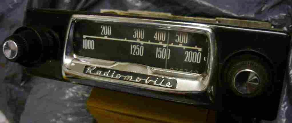
 Model 101 without Tone Control
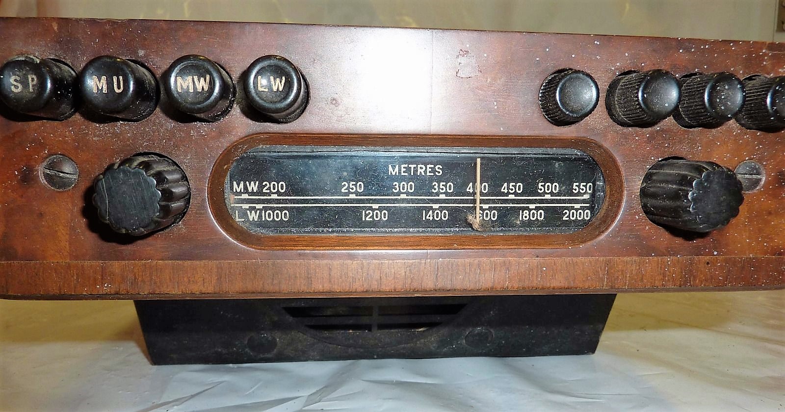
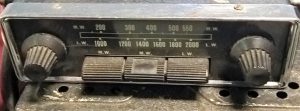
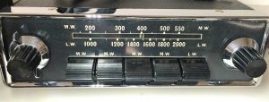
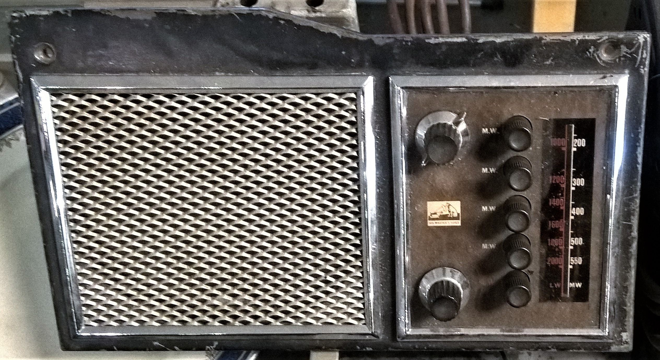
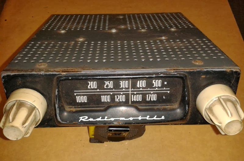
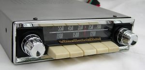
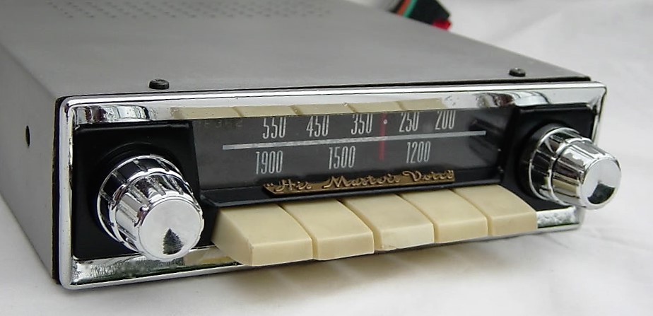
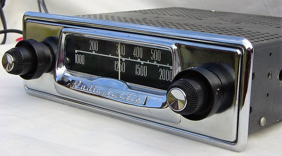
The 100 series were used in most European countries. Medium Wave radios in 1950’s Europe had a scale running from 200 to 550 metres and a Long Wave scale from 1000 to 2000 metres.
2.3 Model 4012 & 4014 (1948 – 1951)
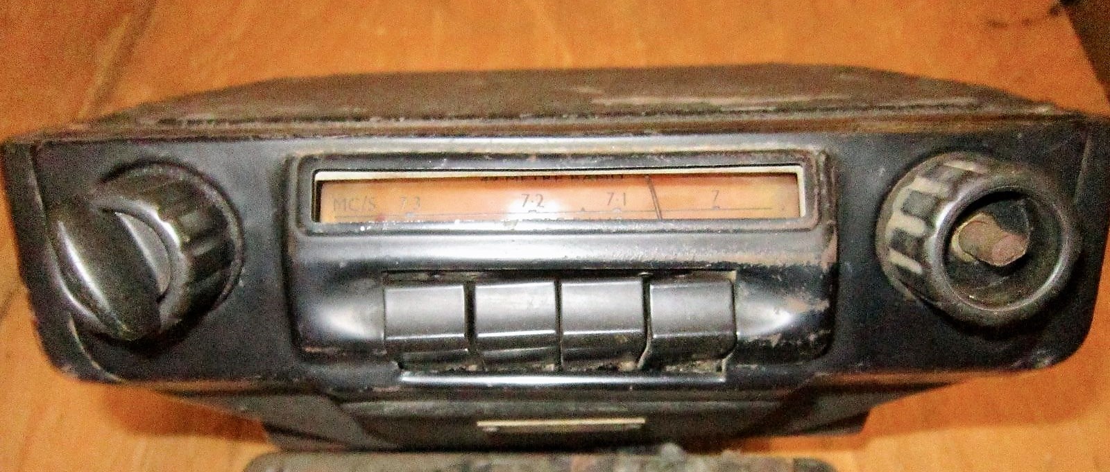
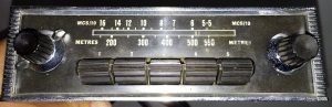
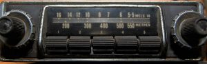
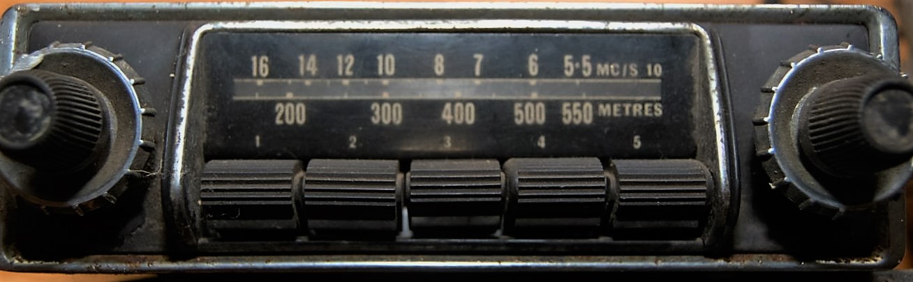
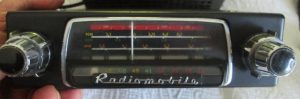
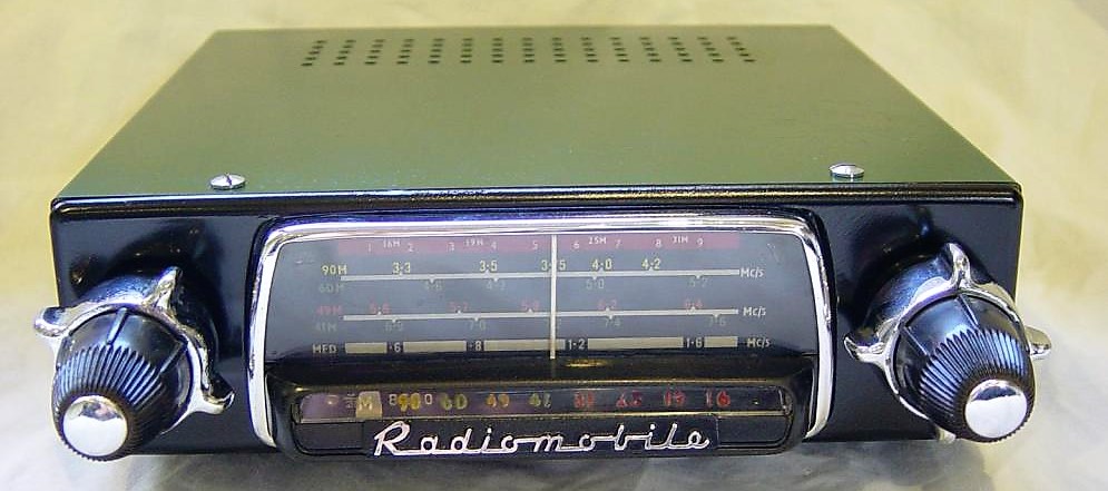
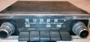
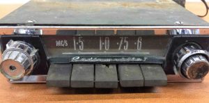
The Model 4012 with Medium Wave was used on the OTS version of the XK 120 in North and South America and some Southern European countries. Whereas in Europe the Medium Wave frequency spectrum had been defined starting from 531 kHz to 1600 kHz, in North America the upper limit run up to 1700 kHz. The radio on the photo below has the MW scale in MHz/10 (instead of metres), running from 16 to 6 so it may still have been a European version. The 4012 used the same power unit as the Model 100 radio and had Jaguar part number C.4608.
 Radiomobile 4012 with MW only
The Model 4014 (Jaguar part number C.4609) with Medium Wave was only used in Australia and New Zealand. In Australia MW radio broadcast allocation was from about 1700 kHz to 535 kHz. Note that radios sold in Australia normally had a special dial face per state with local radio station-codes printed on it.
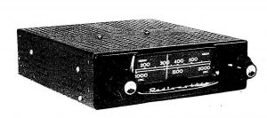
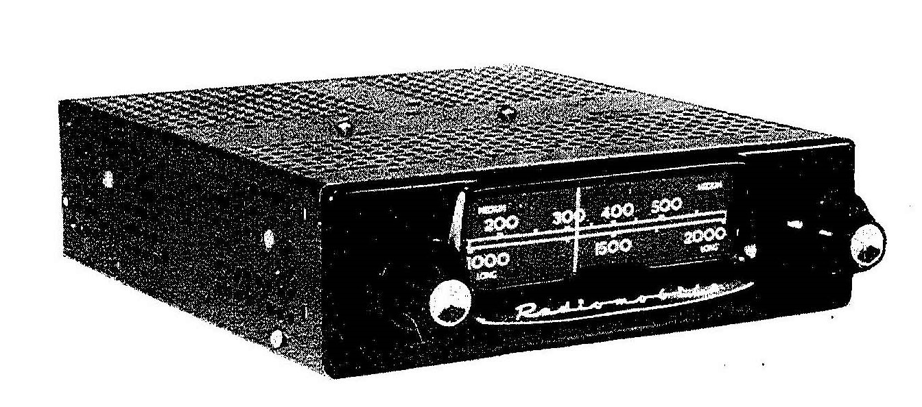
2.4 Model 4050 (1949 – 1951)
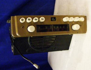
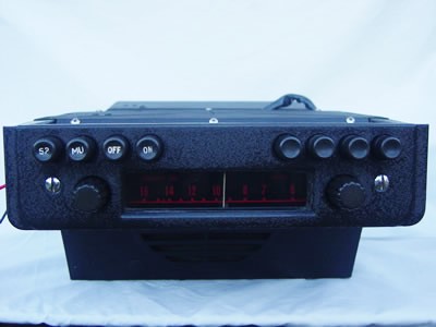
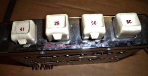
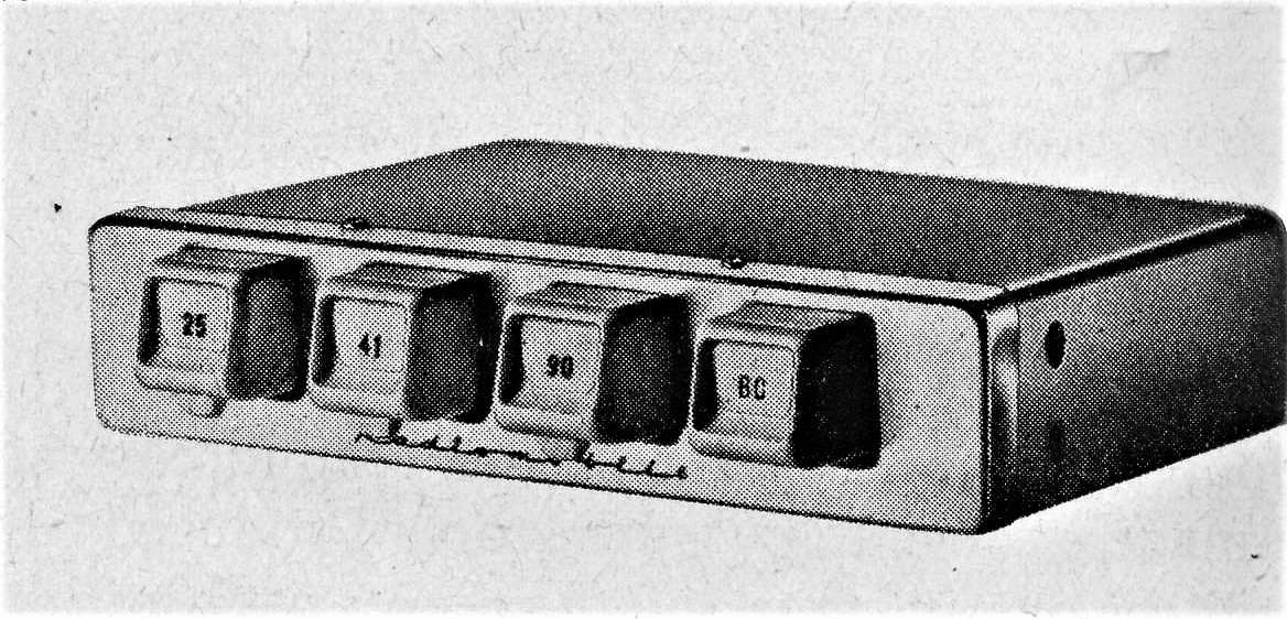
In the autumn of 1949 Radiomobile introduced its first car radio with Short Wave, in addition to Medium Wave. There were 7 Short Wave bands, each with a separate indication on a drum-type tuning scale.
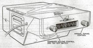
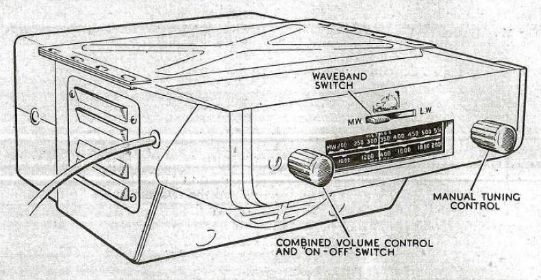
Although part of the “single unit” construction range (like the Model 100) the front of the 4050 was clearly different. It had 4 push buttons (to pre-select Medium Wave stations) positioned below the scale. The “Tone-Control” was done by one turning knob with 4 positions instead of the two tone-control push buttons of the Model 100 version. Apparently the 4050 had the possibility to install a remote speaker.
Model 4050 (Jaguar part number C.4610) was destined for many countries but not for the main markets such as Northern America and Europe and only used on the OTS model of the XK120 (and other contemporary Saloons). Note that the 4012, 4014 and 4050 have sequential Jaguar part numbers.

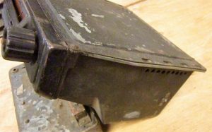 The rare Model 4050 model with 4 push buttons Side view of receiver

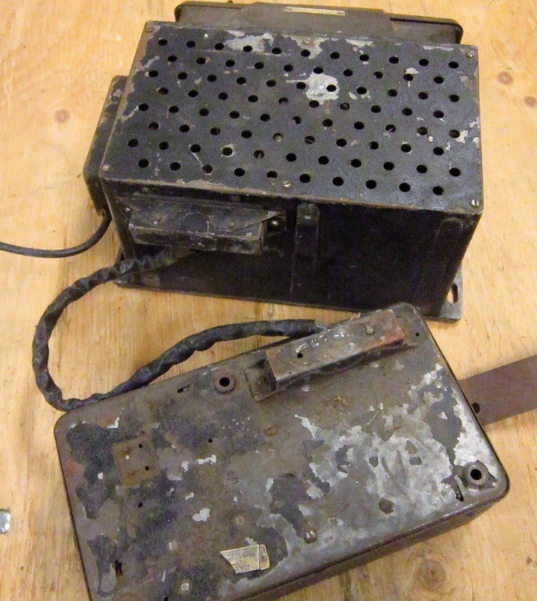
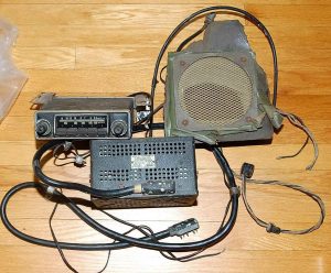
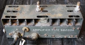
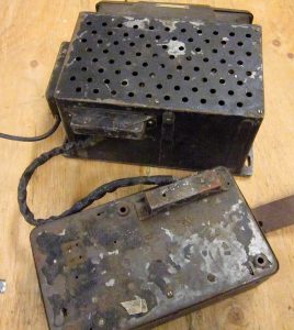 Complete set with receiver (top) and amplifier (bottom)
2.5 Installing the 100 and the 4000 series
If an optional radio had been ordered, Jaguar removed the map drawer of the DHC or FHC version and the radio tuner was installed in its place using special brackets. On the earlier XK 120 DHC/FHC models the wood panel opening had to be widened but cars produced after 31st December 1951 were made with the correct width for the radio receiver: 2 x 7 inch (51 x 178 mm) typically. Remember that the aforementioned versions for the XK 120 OTS were all of the “single unit” construction.
Radiomobile provided instruction booklets for the installation of car radios. For the 1951 successor models (see next chapter) specific instructions are available for the XK 120 models. Instructions do exist for the “Jaguar Mark V 1950-1951 Saloon and Coupe models“, published in May 1951, possibly covering the RM100 and 4000 series. In addition, there is one for “Jaguar Mark VII 1951 models“, published June 1951. (Information: Roger Payne).
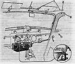

Fitting a Model 100 under the dashboard of an early Saloon(left) and an Austin 12/16 (right) where the amplifier unit has been decoupled and is positioned above the receiver. Note: roof aerial for both cars!
2.6 The 4100 series (1951 – 1955)
Although not part of the “Optional Extras” list of Jaguar, the 4100 series can still be found on Jaguars as it was around 25% “less costly” than the 4200 series and (apparently) offered by Jaguar dealers. It was produced in parallel to the 4200 / 4260 models and may therefore have been used on early XK 140’s as well. Radiomobile referred to the series as having “High Sensitivity” whereas the 4200 and 4300 series had “Super Sensitivity”.
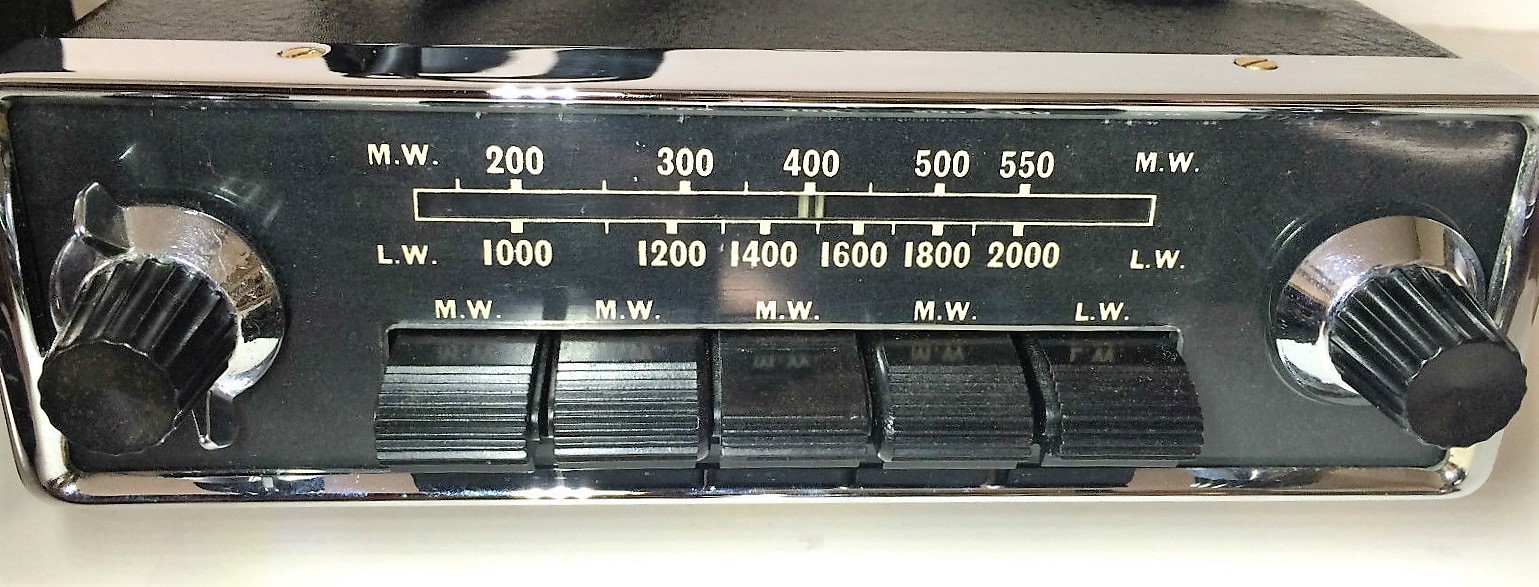
The Model 4100 had LW and MW reception, but only 3 push-buttons instead of the 5 buttons of the 4200 series. It used the same Amplifier Unit as used for the 4200 and 4260 series: only the low power 46028A version was recommended for this receiver. For more information, see paragraph 2.9.
Another version in the 4100 series was the Model 4102, similar to above but with MW only. US Jaguars may have had this particular version installed (branded as Emitron 4102) as LW radio wasn’t required in the USA.
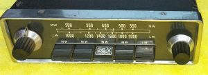
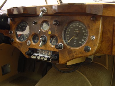
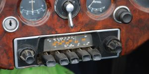
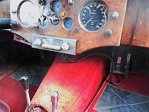 Radiomobile Model 4100 in black. The HMV logo is missing on centre button. Model 4100 in an XK 120.


2.7 Model 4200 & 4202 (1951 – 1954)
In July 1951, an improved version of the Radiomobile 100 and 4000 series became available: the 4200 series. This range was used from 1951 till about 1954. Models that have been offered on the XK 120 are the Model 4200 and Model 4202, introduced on the FHC models in 1951. At the same time the OTS got this radio option replacing the older types and it was also available on the DHC from 1953 onwards.
Model 4200 (with Jaguar part number C.5363) was a Long and Medium Wave receiver, in fact replacing the Model 100 version. It was the first of the “3-unit construction” replacing the “single unit” of the 100 and 4000 series. It had 5 push buttons: 4 for pre-selected MW stations and 1 for selecting the LW band. The face was black with a chromed rim and knobs available in various choices. This “standard” version is shown here below.
 Two examples of Model HMV 4200

The total power output of the radio system could be increased by opting for a “heavier” Amplifier. Radiomobile offered 2 versions: A-type and B-type of which the latter version was recommended and used by Jaguar. The complete car radio is therefore sometimes referred to as Model 4200B.
Model 4202 (Jaguar part number C.5370) was a simpler version of Model 4200 with Medium Wave only. Note that the scale is in Metres and MCS/10. Compare the 4202 front below with that of the 4200 shown above. This version was only available in 1952-1953. The Emitron 4202 version for America was manufactured in a dedicated Jaguar version with the text “EMITRON JAGUAR CUSTOM” instead of the scale indication in Metres (which seems logical for the USA). See also “Original Jaguar XK” by Philip Porter, page 65 of the 2003 edition.
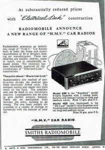
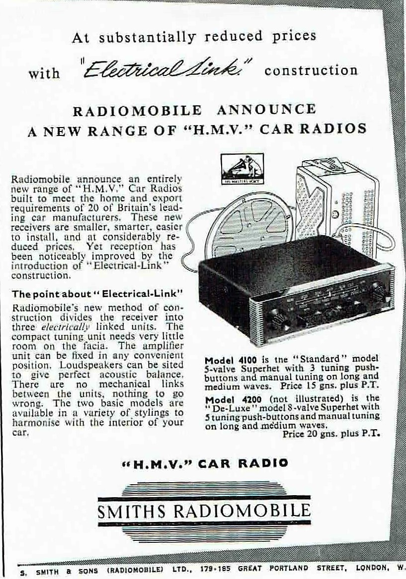
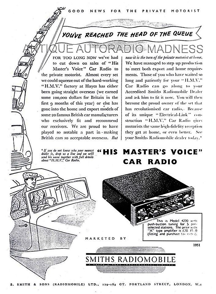
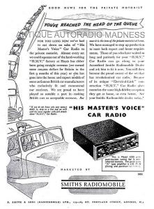 Smiths Radiomobile 1951 and 1952 advertisements introducing the first radios of a “3-unit” construction


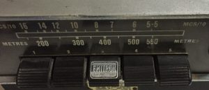 Model HMV 4202 in black Different front Model Emitron 4202
2.8 Radiomobile Model 4220 & 4222
Radiomobile also made ‘brand specific models” on basis of the 4200 series. Model 4220 is such an example, specially made for the Rover P4. The receiver part was positioned vertically and the loudspeaker was placed next to the receiver positioned behind gauze, while the (standard) remote amplifier was connected via a cable with connector plugs. The 4220 series has been derived from the 4200 series,
There were (at least) two versions: Model 4220 with MW and LW and Model 4222 with MW only. Both used the Amplifiers of the 4200 series (see 2.10)
 Typical arrangement of the 4220 series
 Model 4220 with MW & LW


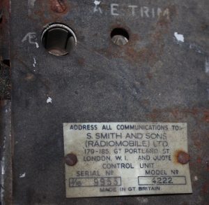 Model 4222 with MW only


2.9 Radiomobile Model 4300 with Long, Medium and Short Wave reception (1954 – 1955)
Although listed for the XK 120 in the Spare Parts Catalogue this radio was in fact more used on the XK 140 and therefore further detailed in chapter 3.
2.10 Amplifier units for the 4200 series
The 4200 series radios had a separate, remote Amplifier unit. There were two different versions of the Amplifier unit:
- Medium output version Type A with nominal 2.5 and maximum 3 Watt output for one loudspeaker
- High output version Type B with nominal 6 and maximum 7 Watt output, suitable for one or two loudspeakers.
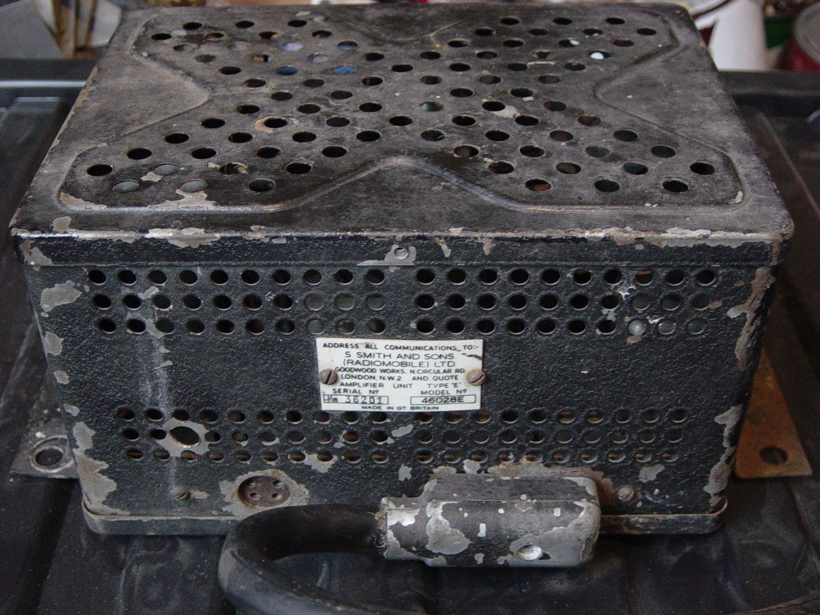
Radiomobile numbers are 46028A and 46028B respectively. There is also a Type E amplifier (coded 46028E) of which the exact application is unclear. Note that Jaguar only used the 46028B version with their part number C.5364.
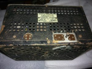
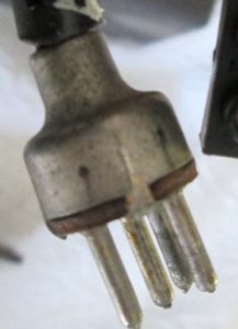
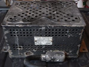 An 8 pin connector cable was used for 46028 Amplifier units.
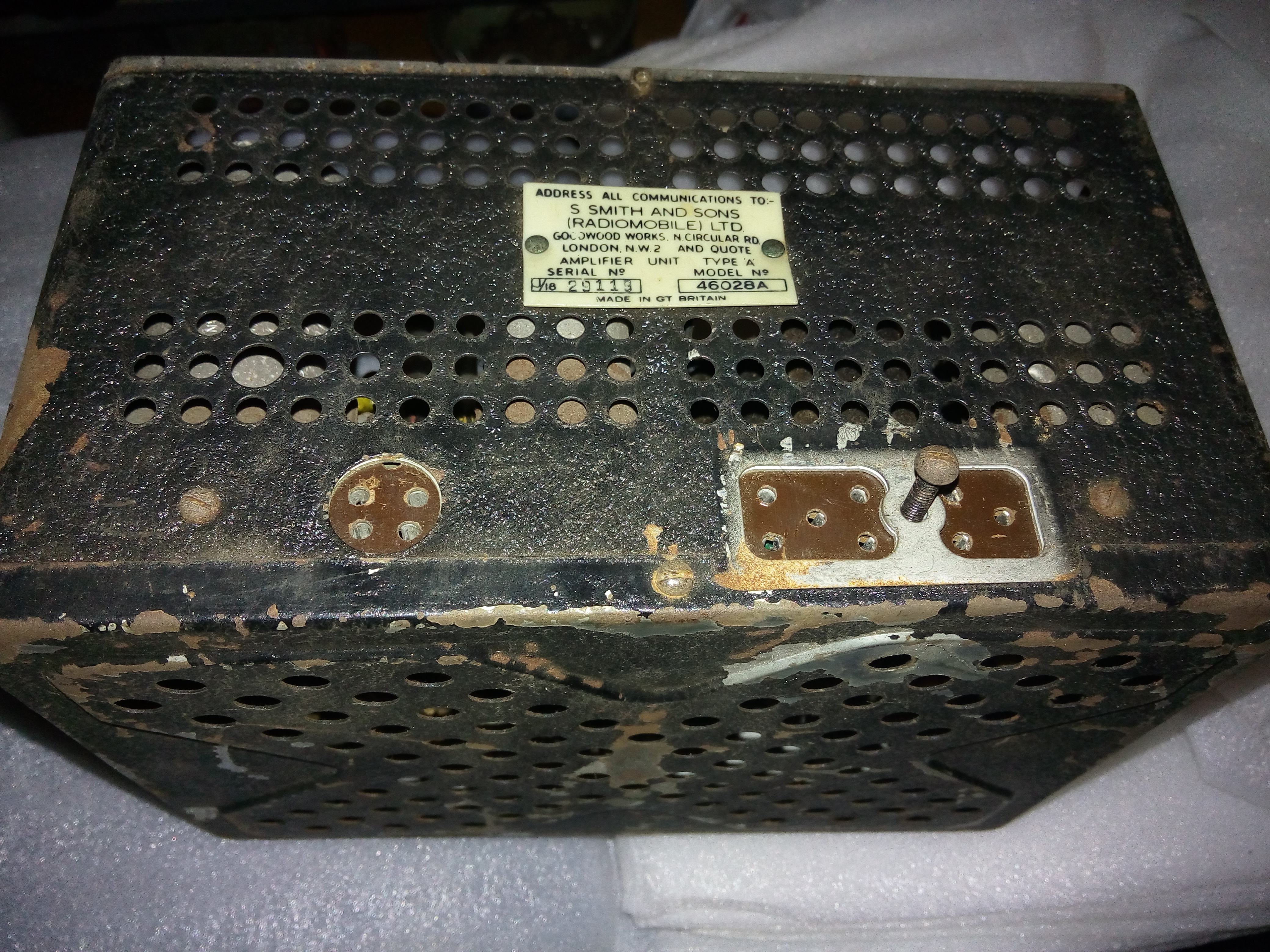
The first generation Amplifier Units had an 8-pin connector system for the cable from Receiver to Amplifier. This system was used for all “3 unit constructions” up to 1955. As we will see in Chapter 3, later generations “3 unit constructions” used a 5-pin connector system and the two generations are therefore not interchangeable! The loudspeaker connection of the first generation used a 4-pin connector and cable; the second generation had a 3-pin system.
2.11 Installing the 4200 series
A small 8-page booklet was published by Radiomobile in January 1952 giving detailed “Installation Instructions for His Masters Voice Automobile Radio Models 4200-4202 Series Smiths Radiomobile“. An instruction booklet exists specifically for the “Jaguar XK 120 Sports 1951 and 1952 Models“. Remember that the XK120 FHC had only been introduced around July 1951.
As mentioned before, early XK 120’s required widening of the drawer opening in the wooden dashboard to mount the Receiver unit. Cars produced after 31st December 1951 have the correct opening dimensions.
The 4200 series were the first of the “3-unit construction” generations and rather different from the previous 100 and 4000 series.
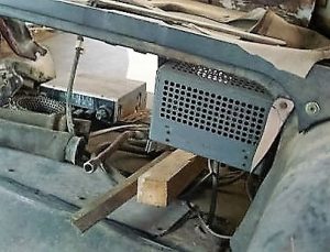
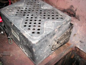 Original 1954 amplifier installation between the Batteries


Note the early Radiomobile mounting bracket with single slit. (Photo’s Rob Reilly)
The Receiver (or Controller) was positioned in pace of the drawer for the DHC/FHC models and below the instrument panel on the OTS version using special mounting brackets (see picture below). As we will see there are three different brackets used for Amplifier mounting between 1951 and 1958:
- Bracket with single slot per side. Radiomobile code unknown.
- Bracket with double slots per side. Radiomobile code RMO3451/BA and/or RMH93508. Jaguar C.11797
- Brackets with no slots for Transistor Amplifiers. Radiomobile code RMO3320/K
The DHC/FHC versions had the Amplifier (or Power unit) placed between the two 6 Volt batteries (positioned behind the seats) using the standard Radiomobile bracket supplied with the unit. The Amplifier unit has 3 sets of screw holes and can be attached at 3 different positions: wall mounted, shelf mounted or under the instrument panel.
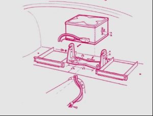 Early mounting bracket with single slits, positioned between batteries (Picture Roger Payne)

A long cable (with 8 pin connectors at both ends) runs from the amplifier to the receiver. The routing of the Amplifier cable is as follows: from the Amplifier Unit (mounted between the batteries) first horizontally to the front of the car at the left side of the transmission tunnel, secured by a “P” clip halfway the tunnel. The cable continues forward following the firewall upwards to the rear of the Receiver. The complete cable is hidden under carpets. See picture above right.
The OTS model often had the Amplifier mounted directly in front of the Radio Control up against the bulkhead, using the standard bracket provided with the unit. The Amplifier cable was much shorter then.
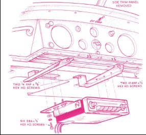
 Special brackets for XK 120 OTS model. Loudspeaker plug with 4 pins on earlier Amplifiers
Cars built after 31 December 1951 had mounting holes pre-drilled and fitted with rubber blanking plugs if no radio installed by factory. The loudspeaker was located behind the seats. Another cable (with one 4-pin connector) connected the speaker with the Amplifier.
Although there are 4 pins on the plug, only 2 wires are used for connecting a loudspeaker. For the connection, we have to make a distinction between Amplifiers of Type A and Type B.
- For Type A amplifiers a speaker with impedance between 3 and 5 Ohms is connected to pins 1 and 2.
- For Type B amplifiers a speaker (or a combination of 2 speakers in parallel) with impedance of 2 to 3 Ohms should be connected to pins 1 and 3. For a (combined) speaker impedance of 4 to 5 Ohms pins 1 and 2 are used.
2.12 Price levels of 4100 and 4200 radio series
The Radiomobile brochure of August 1953 provides insight on the UK price levels of “aftermarket” radio sets per car model excluding installation cost. For the XK 120 Jaguar recommended Model 4200B with a total “kit” price of almost £41 (inclusive of purchase tax). As a reference: a complete XK 120 could be obtained for an amount around £1600 meaning the radio was at least 2.5% of the total cost. The simpler Model 4100 version had a kit price about £10 (about 25%) less than the 4200 series, which may also be the reason this model was rather popular with Jaguar customers.
The 1953 US price list shows two different radios: one for $115 (probably the Emitron 4102 with A type amplifier) and the other for $164 (probably Emitron 4202 model with B type amplifier). A complete XK 120 was between $4000 and $4600 depending on model and executions. The cost for the optional radio was thus between 2.5 and 3.5 % in the USA.
3. Radio installations offered for the XK140
3.1 Available “optional extras”
Whereas the “Salesman’s Data Book” for the XK 120 didn’t mention any radio as Optional Extras, the version for the XK 140 listed three different radio options:
1. Model 4260 with Long and Medium wave
2. Model 4262 with Medium wave only
3. Model 4300 with Long, Medium and Short wave reception.
 Page from Salesman’s data book: HMV 4260/4262/4300 (own photo)
The XK 140 Salesman’s data book had been edited late 1954 on the occasion of the XK 140 introduction as announced on 13th October 1954. Some of these radio models had been replaced late 1954 or early 1955 by versions listed below and we know that many XK 140’s had these later models, but a few 1954 and early 1955 XK 140 models may have these older types. It may also have happened that later XK 120’s had one of the above-mentioned radios installed. Apparently, the 4200 series never received Jaguar part numbers: none of the relevant SPC’s lists these radios. This is rather remarkable, as Jaguar even published UK retail prices for 1954.
In fact, none of the XK140 SPC’s listed any radio available as Optional Extras. There is sufficient hard evidence, however, that the 200 series have been applied on the XK 140 and Jaguar part numbers have been listed in other SPC’s.
- Model 200X with Long and Medium wave
- Model 202X with Medium wave only
- Model 230R with Medium and Short wave reception
Like the 4200 series of the later XK 120, the new HMV Radiomobile radios used on the XK 140 had a receiver, an amplifier unit and a loudspeaker as well as a (long) cable between receiver and amplifier and smaller leads to the loudspeaker.
3.2 Model 4260 with Long and Medium wave (1954 – 1955)
The Model 4260 was a LW & MW receiver basically identical to its prececessor model Model 4200 but the design had been upgraded: the flat front and dial of the 4200 series had been replaced by a chromed rim around the scale and push-buttons. Jaguar still used the black knob and button versions for the XK 140 models, although there are indications that the Mk VII (M) versions may have had cream knobs and buttons.

 Two examples of HMV Model 4260 with cream or black knobs and push-buttons

3.3 Model 4262 model with MW only (1954 – 1955)
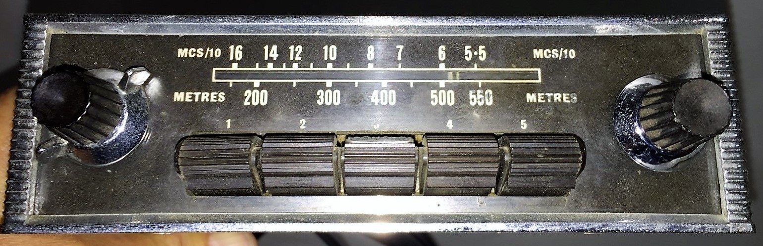
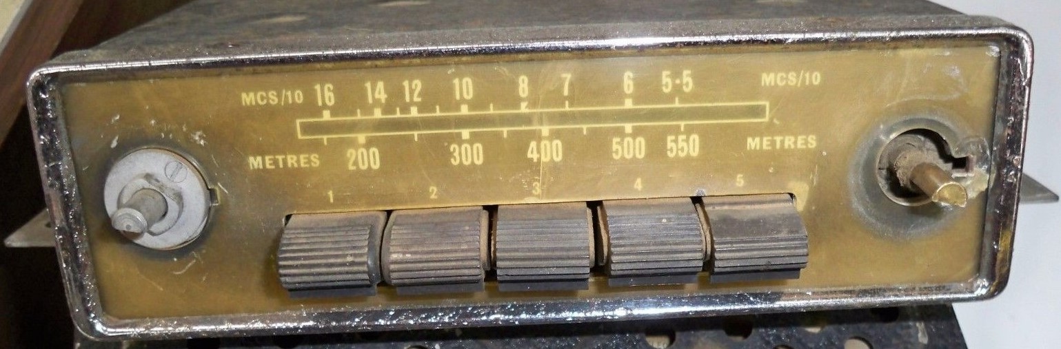
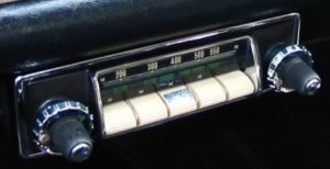
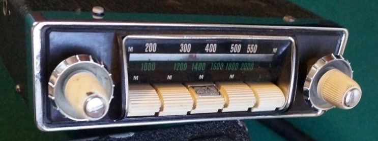
This is a medium wave only radio, with 5 pre-set buttons. All knobs and buttons in black as (most likely) applied for the XK 140 models. The Medium Wave dial showed Metres and MC/S/10 (or better MHz/10) to get the same impression as the two lines of the Model 4260 receiver with one scale for MW and another for LW. Most “MW only” Radiomobile receivers use the same method for their dials.
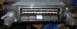
 Model 4262 with black knobs and push-buttons
As stated above, the Model 4262 of the Mark VIIM probabaly had cream push buttons and knobs, as can be seen in the photo below.
 Model 4262 in a Jaguar Mk VII Complete system Model 4262


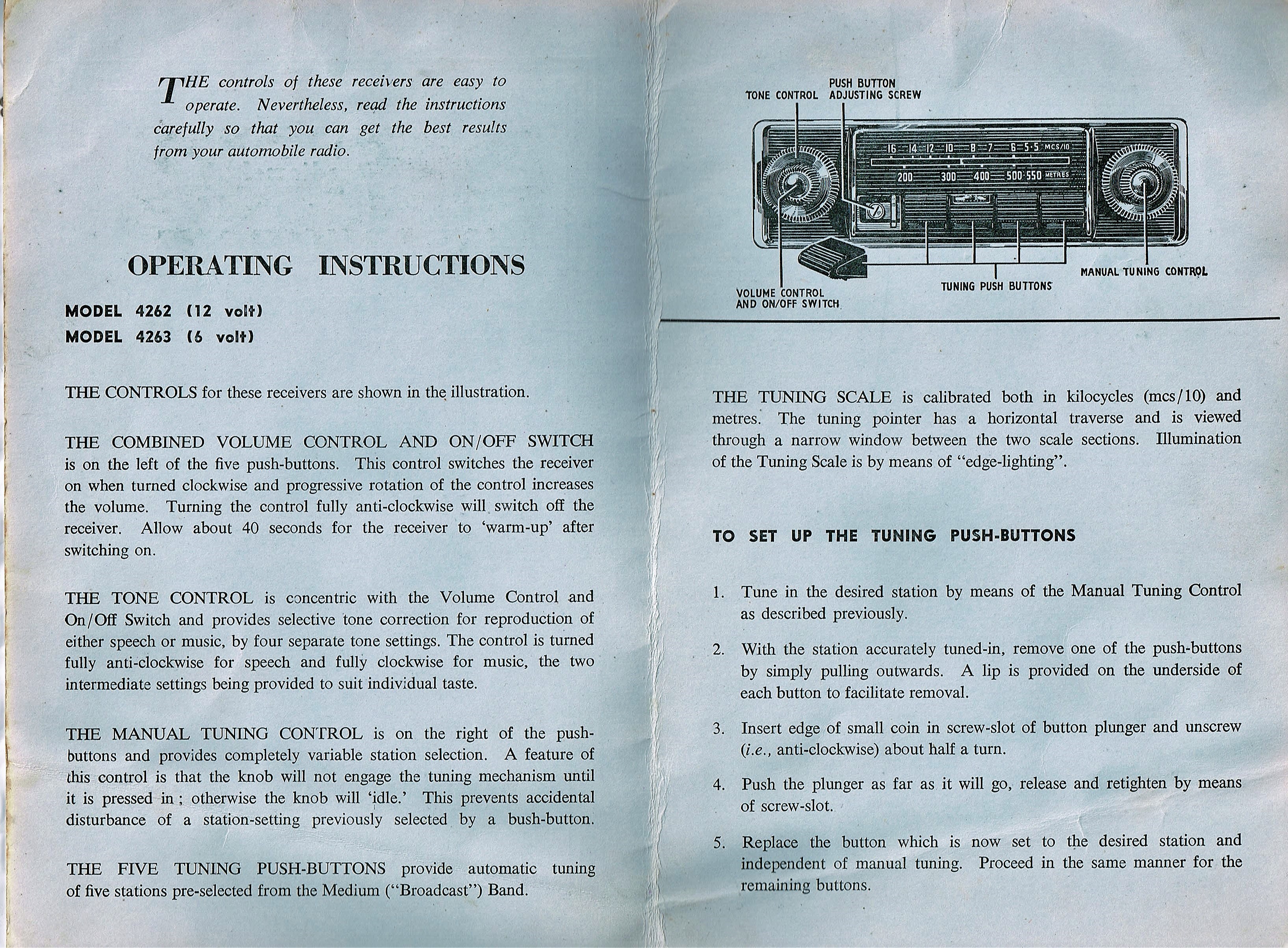
Note that Model 4262 had a specific way of choosing the “pre-sets”, using a screw located behind the front of a push button that had to be removed. See Instructions below.
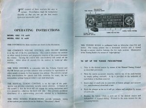 Instructions for Model 4262 dated February 1954 (Courtesy Roger Payne)

3.4 Model 4300 with Long, Medium and Short Wave reception (1954 – 1955)
The Model 4300 was the “high end” model of the 4260 series with Long, Medium and Short Wave reception and it superseded the Model 4050. Although technically related to the Model 4260 and 4262, this version was continued after the 1955 introduction of the Model 200X and 202X (replacing the Model 4260 and 4262).
 Model 4300 in black

3.5 Amplifier units
Two types have been used for the 4260 and 4300 series in the XK 140: Medium Output Type A with a 2.5 Watt output and the High Output Type B model with 6 Watt maximum output. This is a continuation of the Amplifier Units as used for the 4200 series with the 8 pin connector system. Further information: see paragraph 2.9.
3.6 Installation of the 4260 and 4300 series in the XK 140
All radio’s mentioned above were of the “3 unit construction” consisting of a receiver (or controller), an amplifier (or power unit), connected via a thick cable with special 8-pin plugs at both ends, and a loudspeaker. The radio receiver part of the XK 140 was always mounted under the dashboard: for the DHC and FHC instead of the drawer, probably using special brackets replacing the original drawer brackets and slides.
The OTS version had the large separate amplifier (or power unit) mounted high under the dashboard on passenger side as was the speaker (facing down).
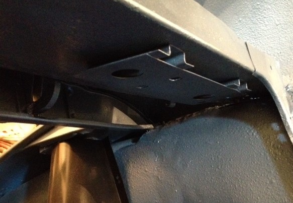
 Later brackets have two slits for horizontal mounting of the Amplifier (Picture provided by Roger Payne)
For the DHC and FHC the amplifier unit was mounted on a steel bracket RMO 3451/BA fixed under the parcel shelf at the LH side of the car.
In case of the DHC the speaker is mounted under the glove box, just as it was for the OTS versions. For the FHC the speaker was mounted in vertical elongated holes forward of the wing vent openings in the side panels. These black bitumen card trim panels actually had a perforated section that could be removed for the loudspeaker. Once the piece was pushed out, perforated aluminium was riveted over the hole on the rear of the panel. The possibility to have speakers on either side probably relates to the different driver positions in case of RHD or LHD cars, although the 7 Watt “High Output” amplifiers could also have two speakers installed.
In case the amplifier unit of the original Smiths Radiomobile is mounted under the parcel shelf in the boot, the (heavy) connecting cable runs under the floor to the radio receiver.
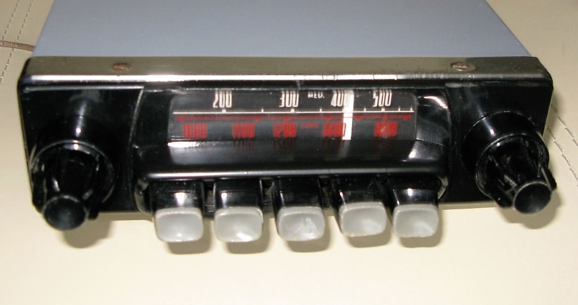
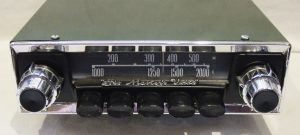
3.7 Model 200X with Long and Medium wave (1955-1957)
The new 200 series, introduced in January 1955, were the successor of the 4260 series and had a more “modern” design with a new HMV logo, but still with 5 push-buttons.
 Introduction of the new Model 200X
The 200 series consisted of two different basic versions indicated by the letter corresponding with the Amplifier used: XB or RB. The Model 200X (as shown below) was combined with the XB power unit.
 Model 200X in an XK 140
The receiver units have the same “looks” and only the type plate will tell whether it’s a X or R version. For the 200 series receivers, the 4 buttons acted as MW pre-sets and the 5th for choosing LW stations (no pre-sets).
Jaguar used a specific receiver version with Radiomobile code RMH200X/VP and Jaguar part number C.11791. Radiomobile offered various choices for push buttons and turning knobs: full black and full white( cream), but also black push buttons with white fronts were an option. And Radiomobile also provided a choice of scales in white/white figures or white/red figures.Some radios had a chrome rim around the front.
Jaguar listed the RMH200X/VP version whereby the letters VP indicate the factory code for dial and knobs/buttons execution. There is ample proof that Jaguar factory-installed radios for the XK’s had fully black knobs and black push buttons with white fronts, but also a few complete black push-buttons have been observed.
 Model 200X radio with white MW and LW scale Model 200X with white scale for MW and red for LW
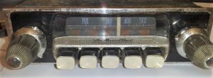 Non-Jaguar 200X radio version with correct push buttons and “His Master’s Voice” on button cover but different knobs and chrome rim.

Note the (plastic) cover over the push buttons; this part is “snapped” to the dial plate with only two little plastic hooks and is therefore often missing after 60 years! Some (European?) versions have “His Master’s Voice” printed on the top of this cover.
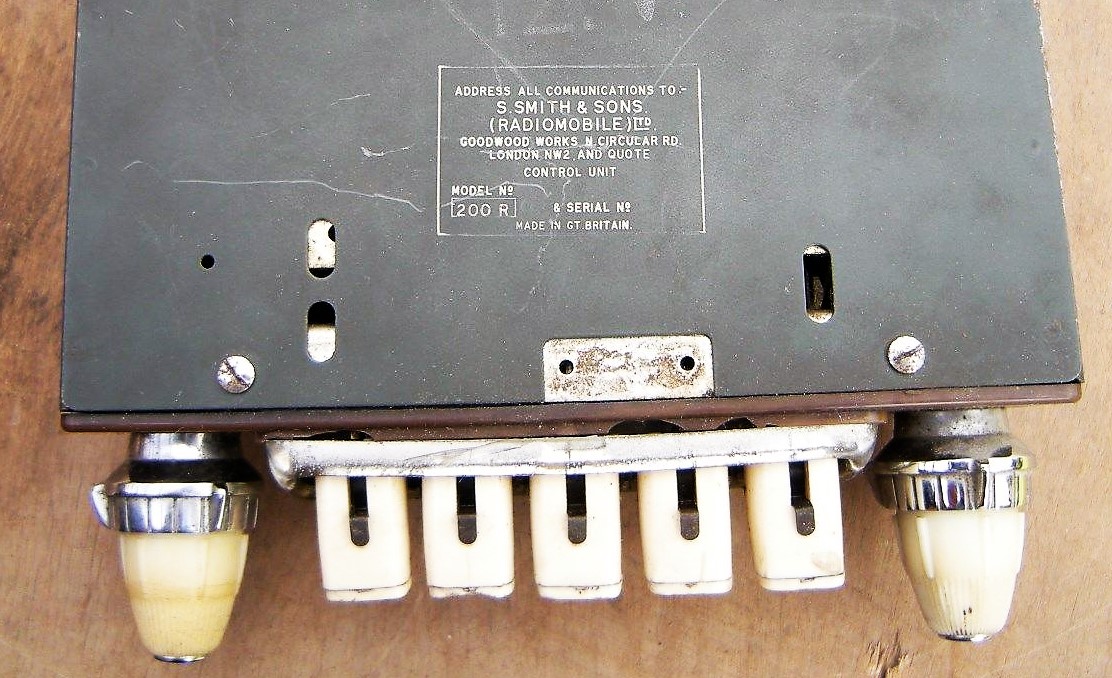
In parallel to the Model 200X there was also a Model 200R to be combined with the more powerful RB amplifier unit. See photos below.

 Front of Model 200R is identical to 200X, To be combined with more powerful RB amplifier unit
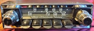
3.8 Model 202X with Medium wave only (1955-1957)
The Model 202X was a popular, simpler version of the 200X with Medium Wave reception only, which was especially sold in the USA. The photos below show versions with cream fronts on the (black) push-buttons which was (as stated before) the case for the majority of factory-installed Jaguar XK 140 radios. All 5 buttons now acted as pre-sets for MW stations.
In line with the above, there also was a Model 202R version to be combined with the more powerfull RB amplifier unit. The Jaguar part number for this receiver was C.11792.
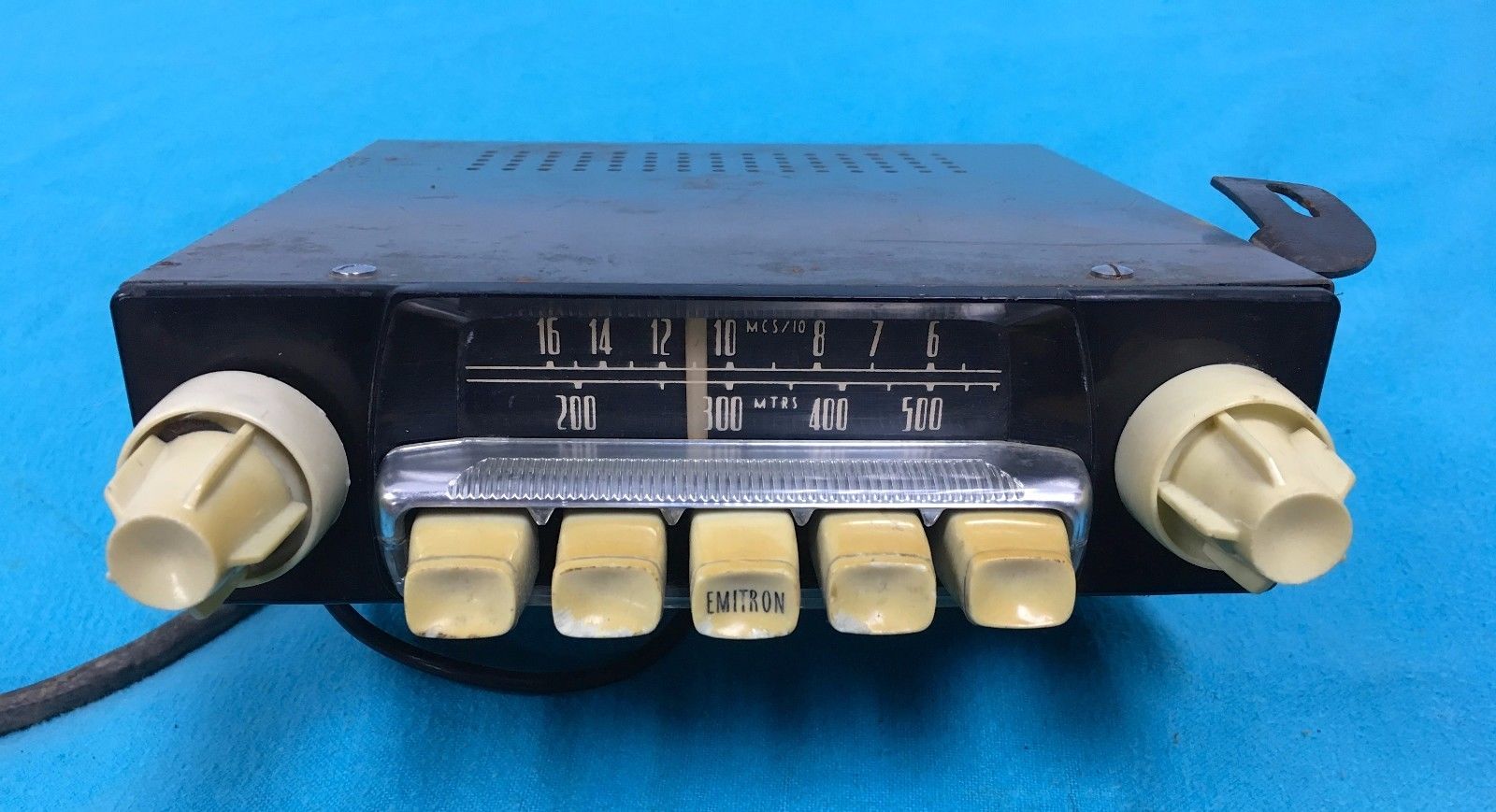
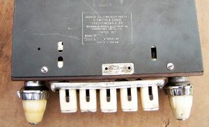
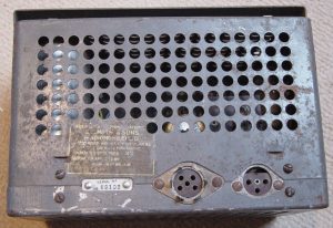
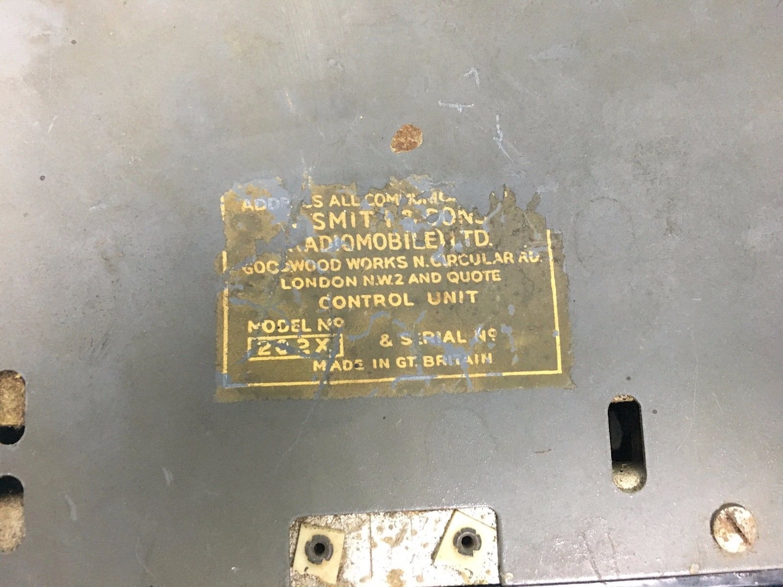 Note that versions for the USA were still Emitron branded/printed for the earlier described reasons. See photos above: note label showing model 202X made by Radiomobile.


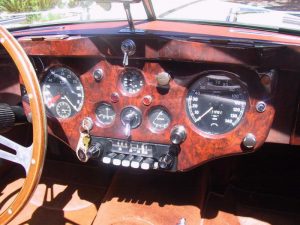
 Five examples of XK 140’s with Model 202X


 Model 202X in Mk VII
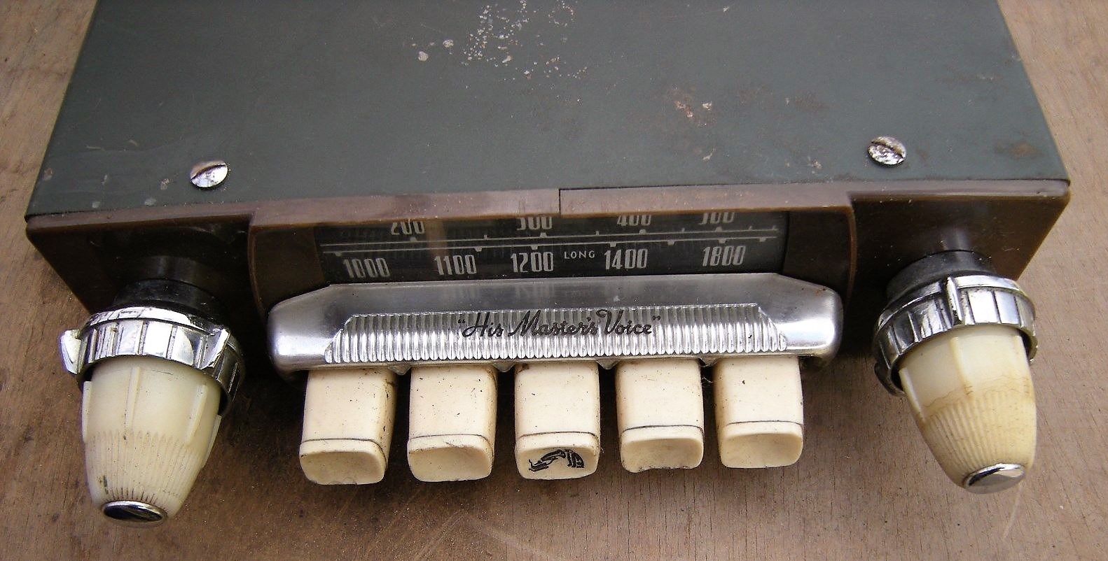
 Special version for Australia with specific stations per state on the scale. Black fronts of push buttons but missing cover (Photo: Roger Payne)

The photo above shows an original HMV (Radiomobile) radio fitted in a late 1954 DHC sold new in Australia. Note the HMV logo on the centre push button. Radiomobile provided special scales per state (or combinations thereof) in Australia to indicate local stations.
 Operating Instructions 200 series radios incl. Emitron in USA.
 Also sold on the Continent: 1955 Belgian ad

3.9 Other 200 series radios
The 200 series was an extensive range with many different models. Again, although not “Optional Extras”, some of these versions may have ended up in a Jaguar XK via dealers especially in the former “Commonwealth” countries. A short survey:
- Model 201X 6 or 12 Volts switchable version of Model 200X.
- Model 203X 6 or 12 Volts switchable version of Model 202X.
- Model 212X 6 or 12 Volts switchable version of Model 200X with adjustable polarity.
- Model 213X 6 or 12 Volts switchable version of Model 202X with adjustable polarity.
- Model 220X 12 Volts only, identical to Model 200X but economy model without push-buttons
- Model 221X 6 or 12 Volts, identical to Model 200X but economy model without push-buttons
Note that each of the above models required a particular Amplifier corresponding with the features of the radio: voltage, polarity and output power. E.g. the Model 220X (a type mentioned by Radiomobile as being correct for the XK 140; see also 3.13) was supplied with amplifier XE and Model 221X with amplifier XF. See paragraph 3.10.
3.10 Amplifier Units for the 200 series
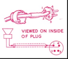
A new amplifier type had been introduced for the 200 series. In order to avoid that later amplifiers could be connected to earlier radios (and vice versa) the new generation had a 5-pin plug instead of the old 8-pin plug system. In addition the loudspeaker cable now had a 3-pin plug instead of the 4-pin system of the previous generation. The “X” range had two versions with a different power output. The new “R” range had an adjustable polarity switch and consisted of 4 types (only 12 Volts versions listed here).
The Radiomobile code for all amplifier units was Model 92450, but followed by the amplifier type e.g. /XB or /RB. Note that Jaguar recommended the more powerfull “B” units only: either 92450/XB or 92450/RB.
For the 200 series Jaguar used only the 92450/XB version with part number C.11796.
- XA 12 V; two valve standard amplifier for 1 speaker; positive to earth; maximum output 2W
- XB 12 V; three valve “De Luxe” amplifier for 2 speakers ; positive to earth; maximum output 5W
- XC 6 or 12 V switch; maximum output 2W
- XD 6 or 12 V switch; maximum output 5W
- XE 12 V; adjustable polarity; maximum output 2W
- XF 6 or 12 V switch; adjustable polarity; maximum output 5W
- RA 12 V; adjustable polarity; 2 valve; maximum output 2W
- RB 12 V; adjustable polarity; 3 valve; maximum output 5W
- RC 6 or 12 V switch; adjustable polarity; 2 valve; maximum output 2W
- RD 6 or 12 V switch; adjustable polarity; 3 valve; maximum output 5W
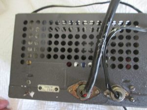 New (round) 5-pin connector type plugs on XB and RB power units. Speaker plug has 3 pins.


 Detail of 5-pin connector plug.

3.11 Model 230R with Medium and Short wave (1955 – 1960)
The Model 230R was a version that “survived” a number of Radiomobile radio generations as it was used for more than 5 years, offered both in the Jaguar XK 140 and XK 150. The model was still of the “3-unit construction” with a separate Amplifier of the RB type. It had a receiver for MW plus 8 SW bands: 90m, 60m, 49m, 41m, 31m, 25m, 19m, and 16m therefore suitable for a number of non-European and non-NA countries. Jaguar describes this version as the RMH 230R/VB, the suffixes indicating the execution of dial and knobs. Note that the 200X and 202X version had suffixes /VP or even /VP.26. Other Jaguar models apparently had different knobs and/or dials: as an example, the Mk2 version had RMH 230R/BCU. The exact meaning of these suffix codes are not known (yet).
 Model 230R was Radiomobile branded, not HMV

3.12 Amplifier Units for the 230 series
The RM 230R was supplied required the more powerful RB amplifier with code 92450/RB. This range of amplifiers consisted of an RA type with single output and the aforementioned RB version suitable for two speakers. See information in 3.10. Jaguar only used the 92450/RB version with part number C.11687.
3.13 Installation of the 200 and 230 series in XK 140’s
The original “Smith Radiomobile installation instruction for 200X, 202X, and 220X for the Jaguar XK 140” describes the radio installation which is in principal the same for OTS, DHC and FHC.
In case of XK 140 DHC and FHC models, the receiver is installed in place of the “drawer” in the instrument panel using special brackets replacing those to which the drawer slides have been mounted. For the OTS model the receiver is mounted with special brackets beneath the dashboard.
Jaguar had mounted a special steel bracket under the parcel shelf for the Amplifier (or Power Unit) during production, whereby the OTS and the FHC models shared the same bracket with Jaguar part number BD.9541: “Plate and Bracket assembly for mounting of Radio Power Pack“. The DHC had a different Jaguar part number for the bracket: BD.8926 “Plate inside Luggage Compartment for mounting of Radio Power Pack when required”.

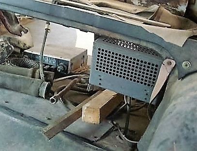
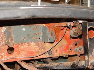
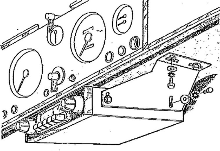
 Jaguar part number BD.9541 : “Plate and Bracket assembly for mounting of Radio Power Pack” in a XK 140 FHC.
The bracket provided by Radiomobile for the amplifier unit was fixed under the Parcel Shelf on the left side in front of the Petrol Filler. All XK 140’s had such a factory built mounting plate, no matter whether a radio had been ordered or not. The XK150 had a similar mounting plate at the left side of the boot (instead of the top).
Radiomobile used two different codes for the Amplifier Bracket: RMH 93508 and RMO 3451. The latter has Jaguar part number C.11797.
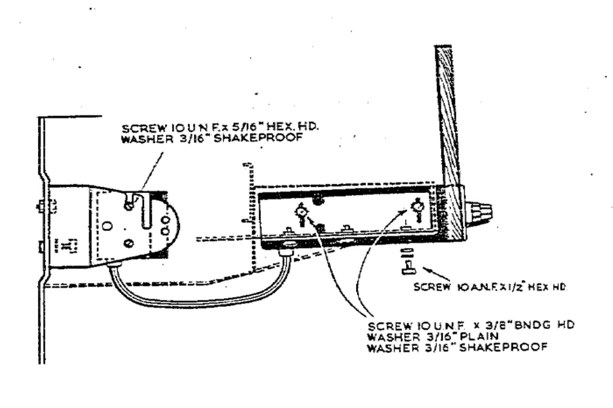
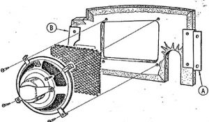
 Amplifier installation method for DHC & FHC models
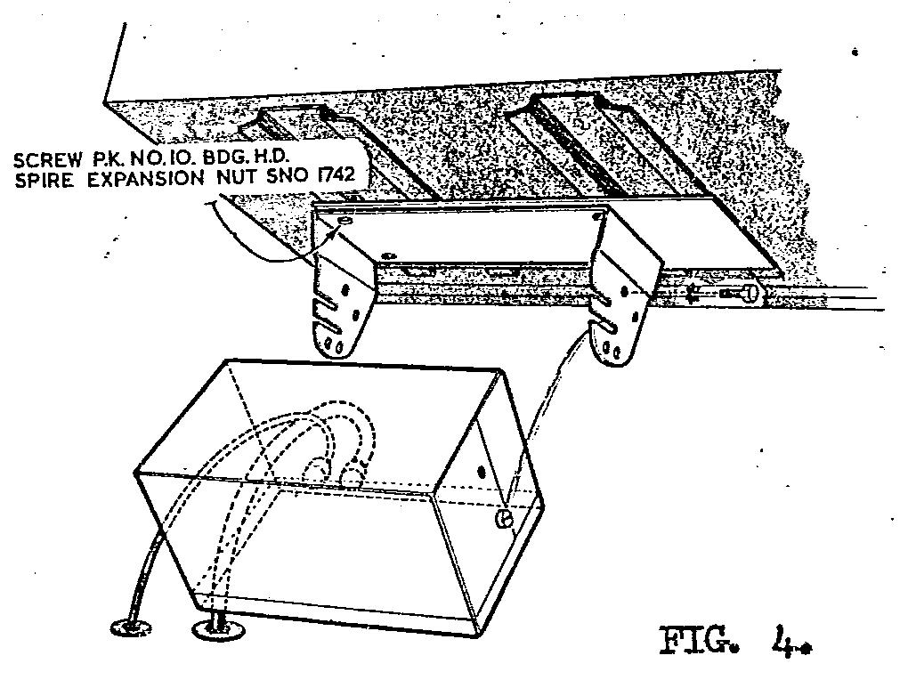
 Later Bracket RMH 93508 has two slots.

The loudspeaker is mounted in a pre-cut hole in the millboard that covers the footwell vent on the right side. This hole has an oval shape roughly 3” by 8” for the standard Radiomobile speaker. The left side had no pre-cut hole.
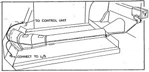 Cable routing XK 140 (and 150)
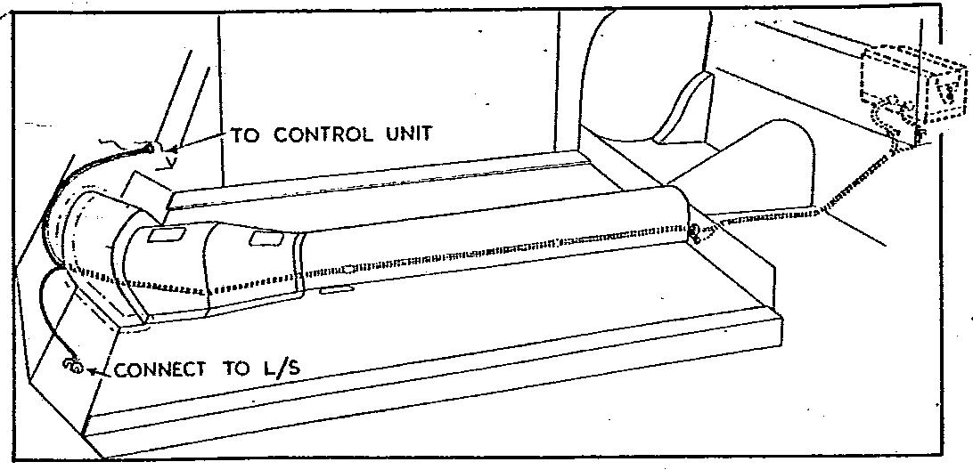
The cable with the two 5-pin connectors runs from the receiver to the amplifier (length 120”or 305 cm) and a second cable with one 3-pin connector (length 168” or 427 cm) runs from the amplifier unit to the loudspeaker in the front.
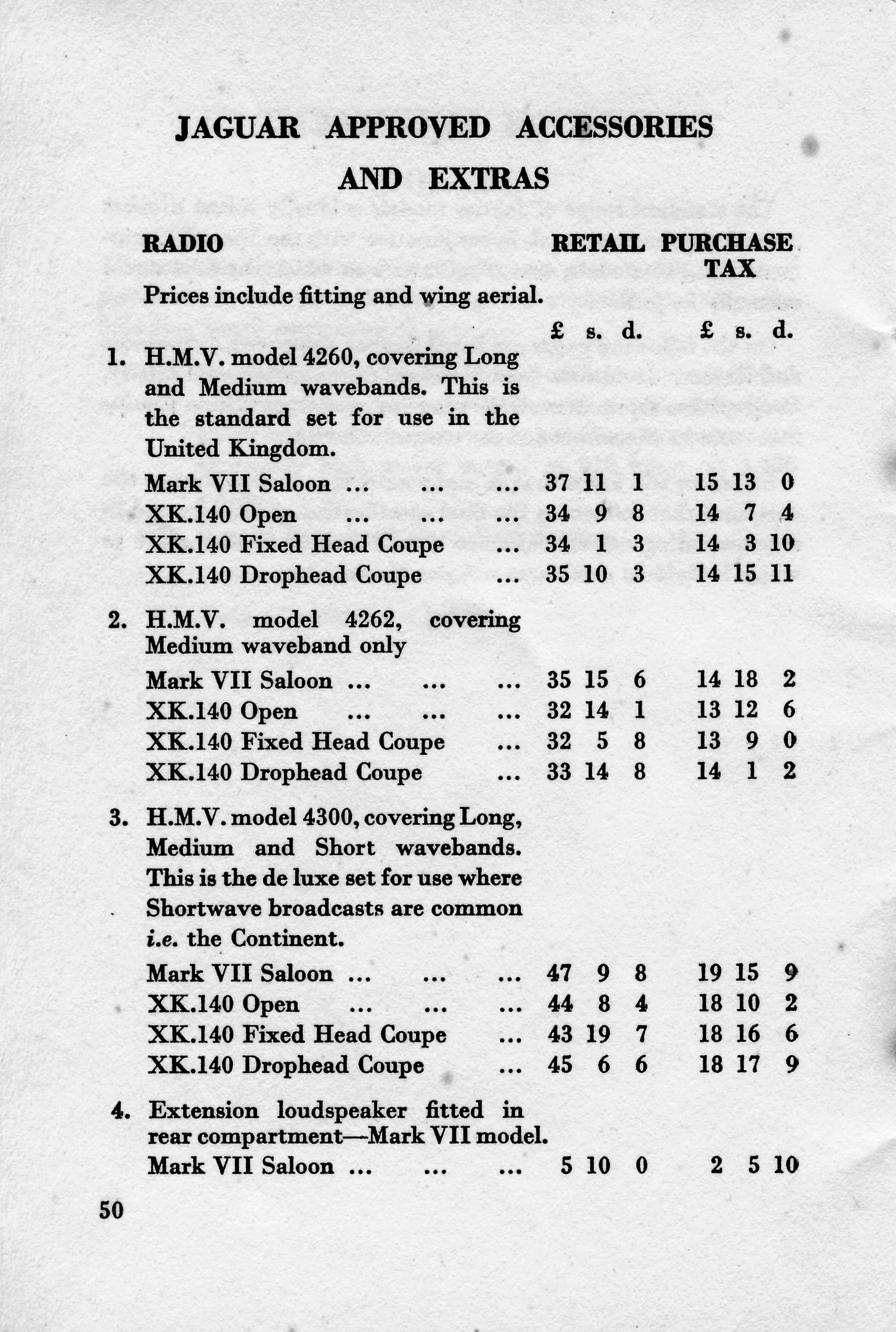
3.14 Typical price levels of 4260 and 4300 series radio systems
The Jaguar 1955 UK price list for the XK 140 shows retail prices around £33 for Model 4262 in the FHC up to over £45 for Model 4300 in the DHC (these prices include fitting, aerial and tax). The total UK price (October 1955) for an XK 140 varied between £1600 and £1860, the latter for the XK 140 FHC in Special Equipment (MC) form, which means the cost of a radio was between 2 and 2.5% of the car.
In the USA prices for the (standard) XK 140 versions had meanwhile been lowered and was now at a level of $3460 (OTS) to $3800 (DHC/FHC) with an additional $450 to pay for the MC version. No 1955 prices are known for the optional radios but we may assume that prices remained at the 1953 level of $115 to $164 or around 3.5% of the total car price.
4. Radio installations offered for the XK150
4.1 Available “optional extras”
It is well known that most Jaguar Spare Parts Catalogue (SPC’s) are not up to date as to the applied parts in production. The XK 150 Spare Parts Catalogue (J.29/1 1960/1966) is no exception and lists the following (1955 introduced) radios available as “Optional Extras”.
- Model 200 X with Long and Medium wave
- Model 202 X with Medium wave only
- Model 230 with Medium and Short wave reception
These radios have already been listed for the XK 140 in the previous chapter and described there in detail.
We first must take a closer look at the way Radiomobile structured their product portfolio. Before 1955 the programme was in composed of high end and low end versions within each new series of radios. From 1955/1956 onwards the portfolio was much more structured having two distinct levels:
- a “low end” Radiomobile branded “single unit” radio combining receiver and amplifier.
- a “high end” His Master’s Voice branded “3-unit” radio (receiver, amplifier and speaker).
Over the period 1955 till 1961 the Radiomobile “low end” single units have been coded 20, 40 and 50 series, whereas the “high end” His Master’s Voice radios were coded 200, 400 and 500 series. It looks like the US delivered “high end” radios gradually were all Radiomobile branded while in Europe the His Master’s Voice brand was continued. After 1961 the “high end/low end” policy continued for some years but the branding became Radiomobile only (starting with the 600-series launched in 1962). The “low end” series remained initially based on the design of the 200 series, without the push-buttons however. The design of the “high end” series moved towards a “De Luxe” version with the His Master’s Voice name prominently shown above the push-buttons.
The Radiomobile Installation Instructions for the XK 150 DHC & FHC of June 1957 mention Model 20X and Model 22X radios in addition to the 200 series. Other available Radiomobile versions have hardly been mentioned in Jaguar literature. However, all below mentioned radios may have been used in the XK 150 and therefore each version will be described hereafter.
For completeness, the Radiomobile Installation Instructions for the Mk VII, Mk VIII and Mk IX of January 1959 mention Model 40T, 41T, 42T, 400T, 401T and 402T as the available options. We may assume that the Mk VII has been mentioned in these instructions for retrofitting these radio types in existing cars, as production of the Mk VII had been stopped in 1956.
- 20 series
- Model 20X with Long and Medium wave
- Model 22X with Medium wave only
- 400 series
- Model 400T Long & Medium Wave
- Model 401T Long & Medium Wave; polarity switch
- Model 402T Medium Wave only; polarity switch
- 40 series
- Model 40T Long & Medium Wave
- Model 41T Long & Medium Wave; polarity switch
- Model 42T Medium Wave only; polarity switch
- Model 42TC Medium Wave; polarity switch; tone control
- 500 series
- Model 500T Long & Medium Wave
- Model 501T Long & Medium Wave; polarity switch
- Model 502T Medium Wave only; polarity switch
- Model 530T Medium & Short Wave; polarity switch
- 50 series
- Model 50T Long & Medium Wave
- Model 51T Long & Medium Wave; polarity switch
- Model 52T Medium Wave only; polarity switch
- Model 52TC Medium Wave only; polarity switch; tone control
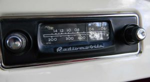
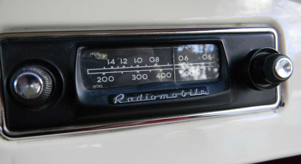
4.2 Radiomobile 20 series (1956 – 1958)
The “20 series”, introduced June 1956, marks the beginning of the era of miniaturization, having a compact “single unit” construction. Although it still contains (3) valves it lacks a separate amplifier unit of the previous generations. For the first time this Radiomobile model had a Selenium Rectifier replacing the vacuum tubes that had been used sofar.
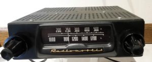
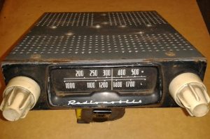 Model 20X in black (left) and with cream knobs (right)

Model 20X is a MW and LW receiver suitable for both “plus” and “minus” to ground. This was the period in which all car manufacturers gradually changed over from positive ground to negative ground and this new model was suitable for both.
As the photo above clearly shows, the 20 series is closely related to the 200 series: the same front lay-out and knobs have been used, however without the push-buttons, necessitating the introduction of a new injection moulded front. The Radiomobile brand name is prominently shown below the scale, which had been started with Model 230. The HMV name or logo is no longer used on these “low end” models. Again variations in colour and shape of knobs were available from the factory.
Model 22X is identical to the 20X version, apart from the fact that this is a MW only radio. Note that there was also a Model 30X which was however a “short-wave converter” to be used in combination with any radio to facilitate SW reception using 8 bands.
Radiomobile also offered Model 30X series, but this was merely a SW converter to be connected to a non-SW radio.
 Model 30X was a SW converter

4.3 His Master’s Voice 400 series (1958 – 1960)
The new 400 series replaced the 200 series by the end of 1958 and still had the “3 unit construction”. Whereas the receiver unit had 5 valves, the amplifier was now fully “transistorised”, replacing the radio valves of the past. As stated before, the His Master’s Voice name is prominently shown on these “high end” versions. The new 400 series consisted of three models: Models 400T, 401T and 402T.
- Model 400T had LW and MW reception with 5 preset push-buttons and had positive earth.
- Model 401T was in fact identical to the 400T version, but had a polarity switch.
 Model 400T

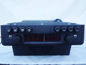
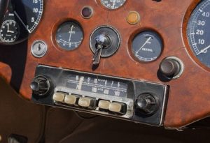
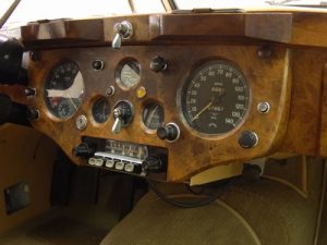
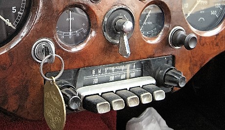
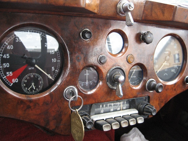
Model 402T also had the polarity switch of the 401T model but was Medium Wave only. Note that on the photo below of a Model 402T, the scale is only showing MC/S (or MHz) values for US customers. Metres are normally used in Europe as we can see on the Model 400T photo above. Note that the 402T shows the Radiomobile brand instead of His Master’s Voice. It looks like the US delivered radios now were all branded Radiomobile while the European (including UK) delivered versions were still His Master’s Voice. The question remains what had happended to the Emitron brand in the late Fifties?
 Radiomobile Model 402T. Here shown in a 1961 XK 150. No His Masters Voice for US customers! Photo: rmsothebys.com


Note that some XK 140’s have been observed fitted with the Model 402X; this must be a later installation.
4.4 Radiomobile 40 series (1958 – 1960)
The 40 series (introduced late 1958 or early 1959) was the successor of the 20 series. Whereas the 20 series had a “X” suffix the 40 series had a “T” suffix for “Transistor”. The 40 series was almost identical to the 20 series but had 4 valves (instead of 3) and an amplifier with a single “power transistor” having a maximum output of 1.75 W, all packed within a single unit. The speakers should have an impedance of 3 Ohms or 1.75 Ohms, depending on the contacts chosen in the (3 pin) speaker connector.
 Model 40T with MW and LW
 Model 42T with MW only
Model 40T had LW and MW reception; no push-buttons. It was delivered suitable for positive earth. Model 41T was identical but had reversable polarity. Model 42T (photo above) also had the reversable polarity but this was a MW only radio. Finally there was the identical Model 42TC which had “Tone Control” in addition.

Underside of 40 series; note Polarity Plug Socket (RH top corner)
4.5 His Master’s Voice 500 series (mid 1959 – mid 1961)
Introduced around 1960, the 500T series was the successor of the 400T series. The amplifier units remained identical for the two series. The 500 series also offered four models: Model 500T, 501T, 502T and 530T. The 500 series had “oval” instead of “square” push buttons. It was replaced by the 600T series in September 1961.
This model is listed in the Mk IX Spare Parts Catalogue, but we know it was also available for the XK150 in the 1960’s. Only the RMH.500TB and the RMH.502TB have been listed by Jaguar with Jaguar part numbers 8265 and 8264 resp. Note that the B behind the T suffix of the receiver refers to the amplifier type that is used in combination with this receiver: here the RMH.98200B with Jaguar part number 8267. See more info in 4.7. Note that the 500 series was also used in very early E-types, succeeded by the 600 series from mid 1961.
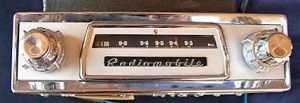
 Model 500T with black knobs and “oval shaped” push-buttons

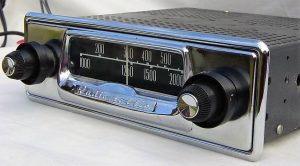
 Model 501T is identical to 500T but has polarity switch (not yet required for Jaguars of this period)

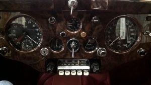
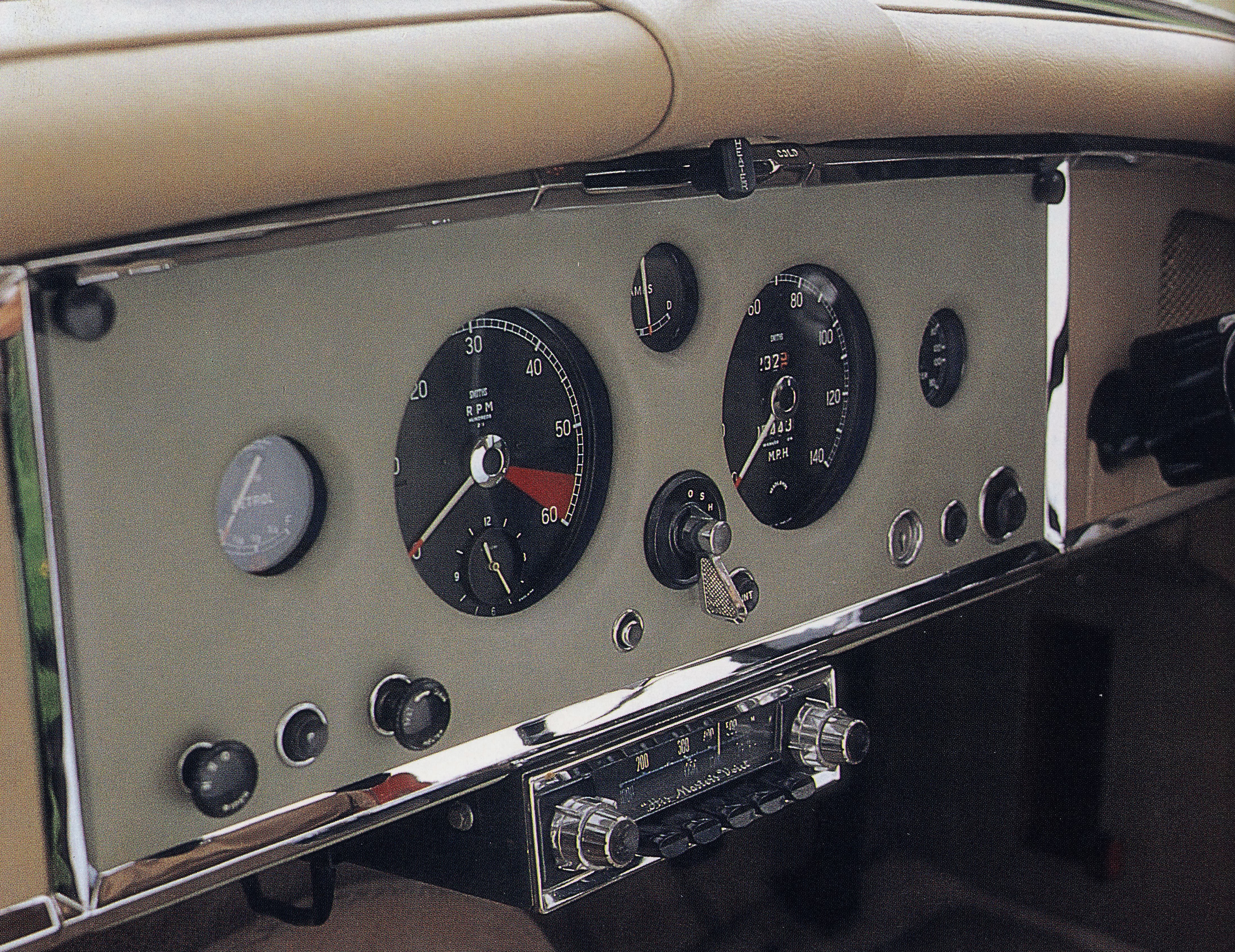
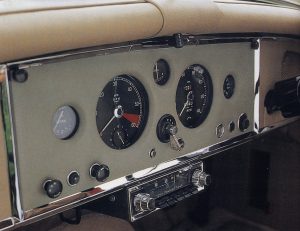 Model 500T in XK 150. Note the speaker grille mounted in the dashboard above the steering wheel Photo: Duncan Wherret, Jaguar XK 120/140/150
Model 500T (positive earth polarity only), was nearly identical to its predecessor Model 400T. In line with the 400 series portfolio, Model 501T was identical to Model 500T but had a polarity switch, whereas Model 502T had MW only (and a polarity switch).
 Operating instructions for 500T and 600T. Latter shows various available models as per 500T series.
Note: 600T is “Radiomobile” and no longer HMV. Photo Roger Payne
The 1961 Jaguar Mark X SPC lists yet another 500 series model: Model 530T. This is a Medium & Short Wave radio that has been coded similarly as Model 230 of the older 200 series. Although we only see one dial the whole inner scale rotates when the wavelength knob is turned. The following scales are shown: MW, 90M, 60M, 49M, 41M, 31M, 25M, 19M, and 16M. Unlike the other 500 series models the 530T model has no push buttons and is also in that respect a successor of Model 230.
Jaguar lists this version as 530TB/VA with part number C.22931 and C.24489. This model is also used on “S” series and various E-types of the Series 1.
 Model 530T with MW & SW

4.6 Radiomobile 50 series (1960 – 1962)
The 40 series was rather short lived as the 50 series replaced the (introduced late 1958) 40 series in 1960. Same model programme as for the 40 series with respectively Model 50T, 51T, 52T and 52TC. The 50 series had 4 valves and 2 transistors, just like the 40 series.
Model 50T is a MW and LW receiver without polarity switch (positive earth only). Note the RH turn knob for band choice with L and M. Model 51T is identical to the 50T however had a polarity switch.
Model 52T and 52TC are identical to the 51T but have Medium Wave only; Model 52TC has in addition “Tone Control”. Note that the scale of Model 52T is in MC/S (or MHz) as we have seen on Model 402T.
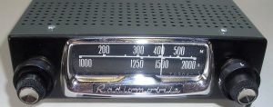 Model 50T
 Model 51T with polarity switch
4.7 Amplifier units for the 400 and 500 series.
Two Amplifier units are used: the A or B Type with 1 respectively 2 transistors. Jaguar opted for the B type amplifier with code 98200B both for the 400 and 500 series with Jaguar part number 8267.
There was also a 98200K amplifier which had an additional heat sink, probably for tropical applications.
Various brackets exist for installing these Amplifiers. The bracket below has Radiomobile code RMO 3320K. Note the large transistor(s) and aluminium cooling fins.
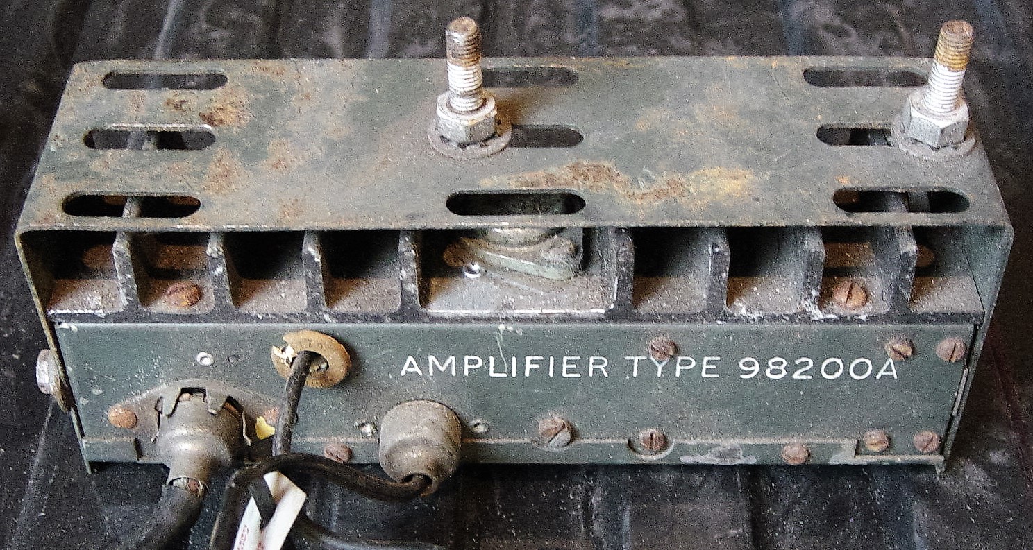
 98200A; not recommended by Jaguar
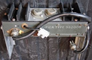 98200B as used by Jaguar

4.8 Installation of the 200, 400 and 500 series as well as 20, 40 and 50 series in the XK 150
Note that the installation of the above models in the XK 150 is identical to the method described for the 200 series in the XK 140, but only using the special mounting brackets of the XK 140 OTS as the XK 150 has no wooden instrument panel. In case of Automatic versions (with the selector handle under the dashboard), extra long brackets were used to lower the receiver installation (see photos below).

 Special brackets for RM 20, 200, 202 and 230 in XK 150 Loudspeaker fitting in XK 150 dashboard

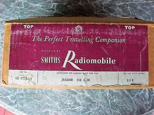
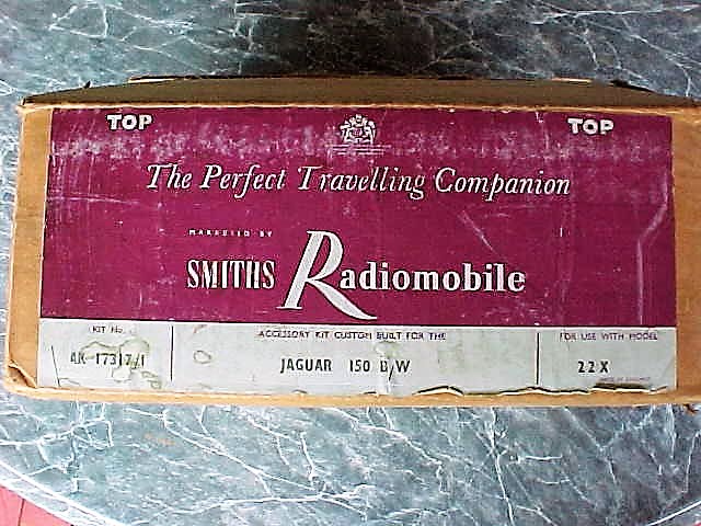
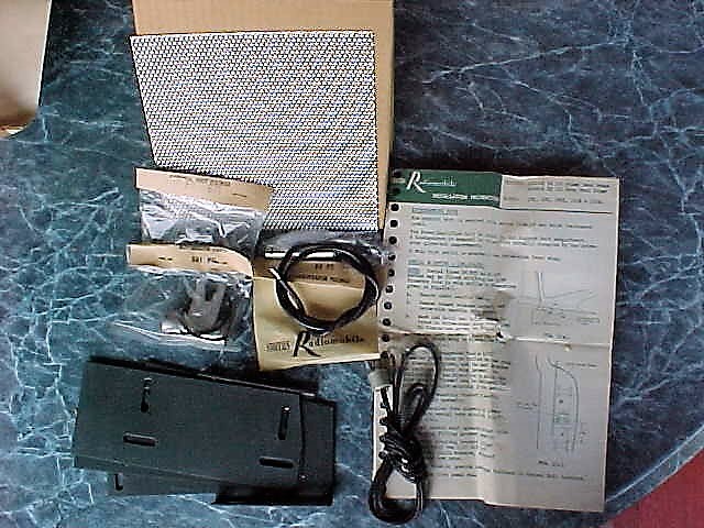
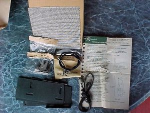 Original Smiths Radiomobile accessory kit for installation of Model 22X in XK 150 with Automatic (BW)
4.5 Typical price levels of the 20 series radio systems
The XK 150 FHC sold for around £ 1950 in the UK by Spring 1958 (in standard form), while an Optional radio was listed from £35 upwards. We notice in general that radio prices dropped as a percentage of the total cost of the car below 2%. This trend continues after the introduction of the new XK 150S when we relate the cost of optional radios to a selling price £2065 in 1958.
US selling prices for the XK 150 and XK 150 S had increased by 1958 to a level of $4550 and $5150 (respectively) for standard versions. Radio price levels (apparently) had dropped to a level around the $ 100 mark meaning the cost of an optional radio had come down to around 2% of the car price. This may also have been influenced by the introduction of “transistor” radios, gradually replacing the valve type of radio.
5. Observations and conclusions
The period 1948 to 1961 was an interesting one as we witnessed the change-over from the “vacuum radio tube” technology towards the new “semi-conductor” era. This is not only reflected in miniaturization of equipment, but also by a steady increasing performance with respect to quality of reception and sound, as well as output power for the loudspeakers.
The first Radiomobile products, starting 1946, were “individual developments” lacking an overall product portfolio approach, which is not surprising for a newly established company. These first Model 100 radios (but also the 4000 and 4200 series) received continuously new updates and derivatives were added “as the need arose”. Within this range, new low-end versions were created by simply offering less features. This also included adaptions to geographical differences, like offering “MW only” versions (e.g. no LW for USA).
By 1955 Radiomobile management introduced a new comprehensive product portfolio concept with typically two ranges: a low-end and a high-end range having each a different “platform”. This portfolio was consistently further developed into the Sixties, whereby the logic of product codes remained the same, contributing to a better and immediate market acceptance of new versions when introduced.
It is interesting to see how Radiomobile dealt with the situation regarding the “His Master’s Voice” rights in North (and South) America. The company’s initial intention was to use the HMV name and logo throughout their portfolio, which became also clear from various magazine and newspaper advertisements using the slogan: “The new HMV Car radio by Radiomobile”. However, due to the existing RCA rights in North and South America, the policy using the HMV brand and logo had to be abanded in the USA: their most important export market! The Emitron brand, chosen as a substitute, did not have the same market impact and also lead to “double branding” for most of their products.
Via an intermediate period of having HMV branding for the high-end range and Radiomobile for the low-end versions (with exception for the USA where around 1955/1956 Emitron had been replaced by Radiomobile for high-end radios as well), the company finally felt strong enough to completely omit the HMV brand in favour of using Radiomobile for all versions all over the world.
Pre-EEC national homologation of vehicle lighting
Approval marks for (continental) Europe
In 1976 the new European Regulation76/761/EEC on “motor-vehicle headlamps which function as main-beam and/or dipped-beam headlamps and to incandescent electric filament lamps for such headlamps” became mandatory for all EEC member states. This replaced the various national regulations in action so far. A survey of known earlier national regulations in Europe is found hereafter.
European countries (except GB) required a headlamp that fulfilled certain legal requirements regarding a “sharp cut-off” dipped beam in combination with a high light output.
France
The French Ministerial Decree of 8th October 1929 formulated a new regulation for car lighting, becoming effective per 1st May 1930. According this decree all cars shall have lighting equipment that should be able to:
- Light the road over 100 metres (indicated with the letter A)
- To suppress any blinding, without ceasing to light the road, when encountering other road users (indicate with the letter B)
All headlights developed to fulfil the above requirements will be investigated by a committee of the Ministry of Public Works (Travaux Public) to receive a conformity mark mentioning e.g. Agréé AB (Certified AB). All headlights mentioning Agréé AB are followed by the letters TP (Travaux Public) and the number of the certification of the homologation (№ 123) issued by the committee.
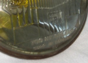 Lucas lamp with French mark Agréé AB-TP No 457

Source: Optique des projecteurs d’automobiles; Editions de la Revue d’Optique théorique et instrumentale 1930.
Netherlands “The myth of the NL mark”
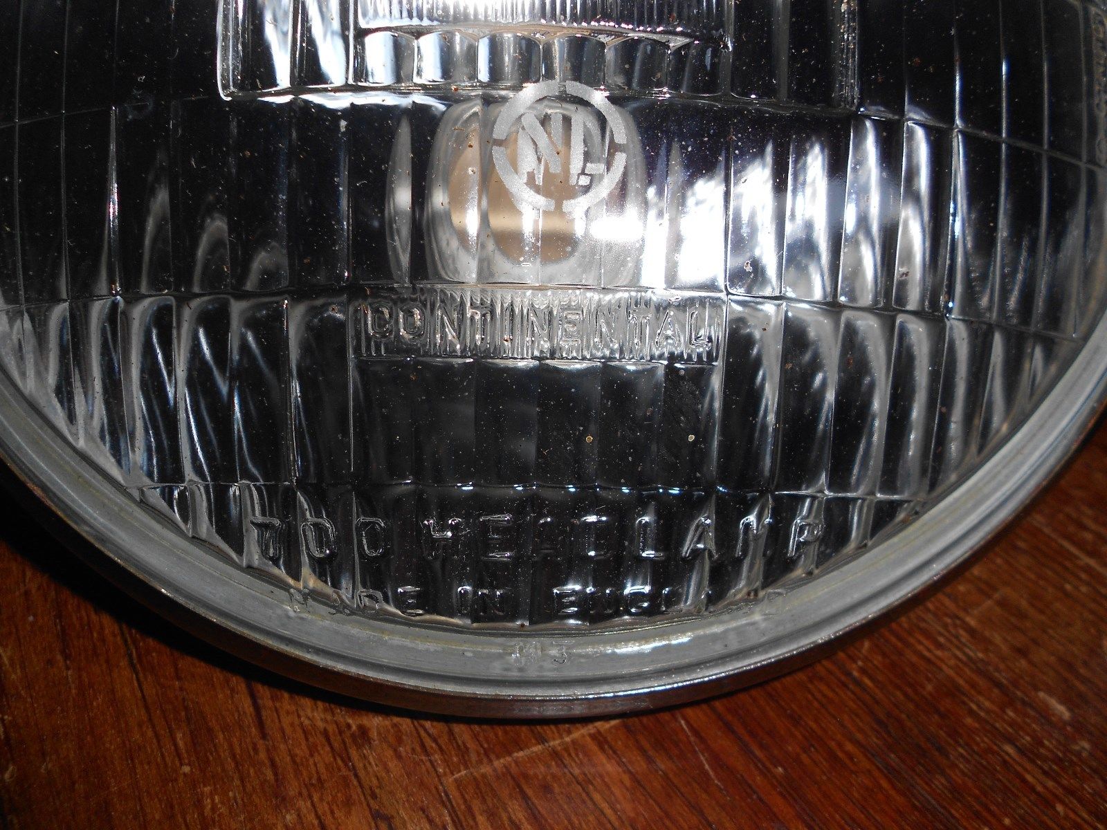
Per January 1st, 1954 a new law had been introduced in the Netherlands that all lighting (and bulbs) of all vehicles on the road should have a “state approval mark” in order to increase road safety. The requirements had been laid down in this law and testing requirements had been assigned to (and consequently drafted by) the Dutch electrical testing Institute KEMA. The “state approval mark” should be clearly visible on the relevant part. From that moment onwards all approved vehicle lighting (from bicycle rear-lamps to car headlamps) carried the NL mark.
All stories (often referred to in GB or USA) about NL meaning “not legal” or “near left” are incorrect: it merely was a type approval for the Dutch market required to sell cars in Holland.
KEMA was (and is) a leading European (ISO certified) laboratory in the area of electrical safety and the KEMA approval mark is still found today on many electrical products.
 Lucas 700 Continental 553940 with NL mark
Germany
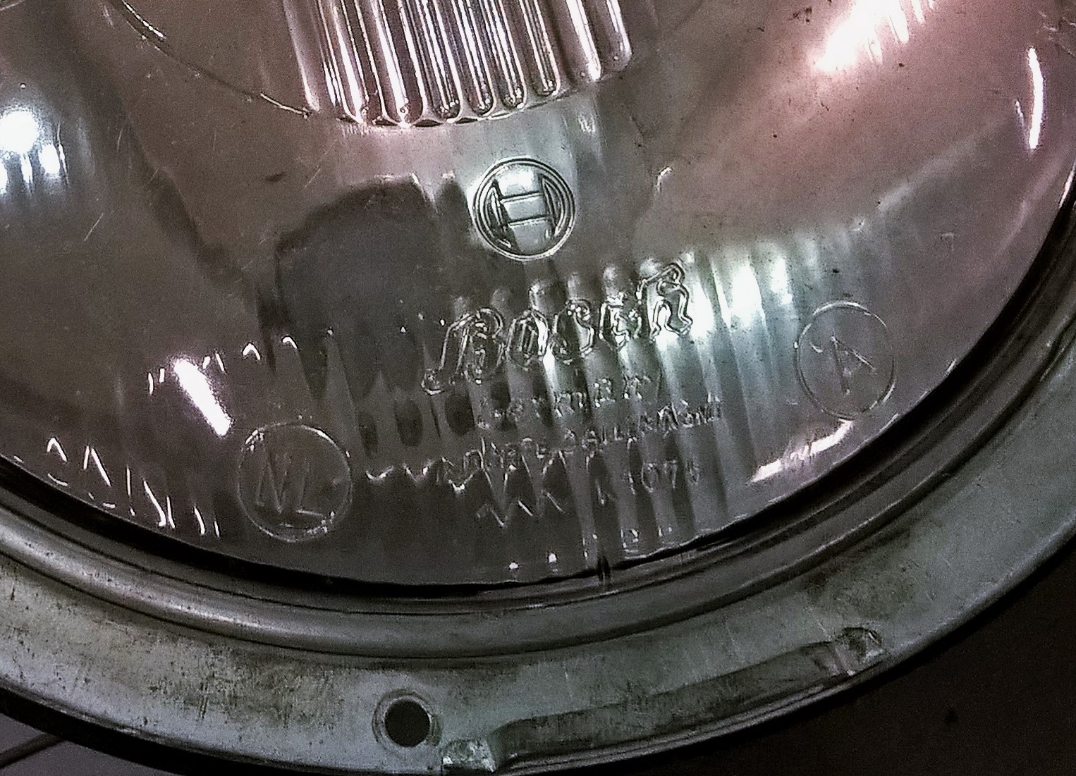
According the „Straßenverkehrs-Zulassungs-Ordnung“ StVZO (Road Traffic Approval Regulation) lighting components on vehicles (generators, headlights, rear lights, reflectors) have to be made according an officially approved construction. The first Regulation dates from 13th November 1937. To show conformity, the German Transport Ministry (KBA) in Flensburg provides an approval mark on manufacturers request. It consists of a wave line with the letter K followed by the testing number.
Example: K 12345
The approval mark is placed on every approved light-technical element of the vehicle. The approval mark is obtained if components meet the applicable Technical Requirements (German: Technischen Anforderungen TA). This TA consisted of Annexes to § XXIIa of the German StVZO. Vehicle lighting without an approval mark shall not become commercially available nor sold; doing so is considered a felony.
Testing is not performed by the German KBA, but by the Licht Technical Institute of the Karlsruhe University, which is also shown in the letter „K” in the approval mark. The German KBA in turn checks the conformity to requirements, initiating regular tests of randomly obtained products from the production line.
 Bosch headlamp with K, NL and A approval mark
Today certain elements of this regulation is still applicable to Bicycles, whereas EEC/EU regulations have taken over other transport segments.
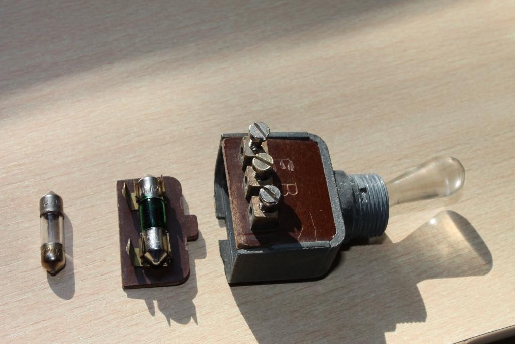
Conversion Trico switch PS-33A to PS-4A
Conversion Trico switch PS-33A (3 positions) to Trico PS-4A (2 positions)
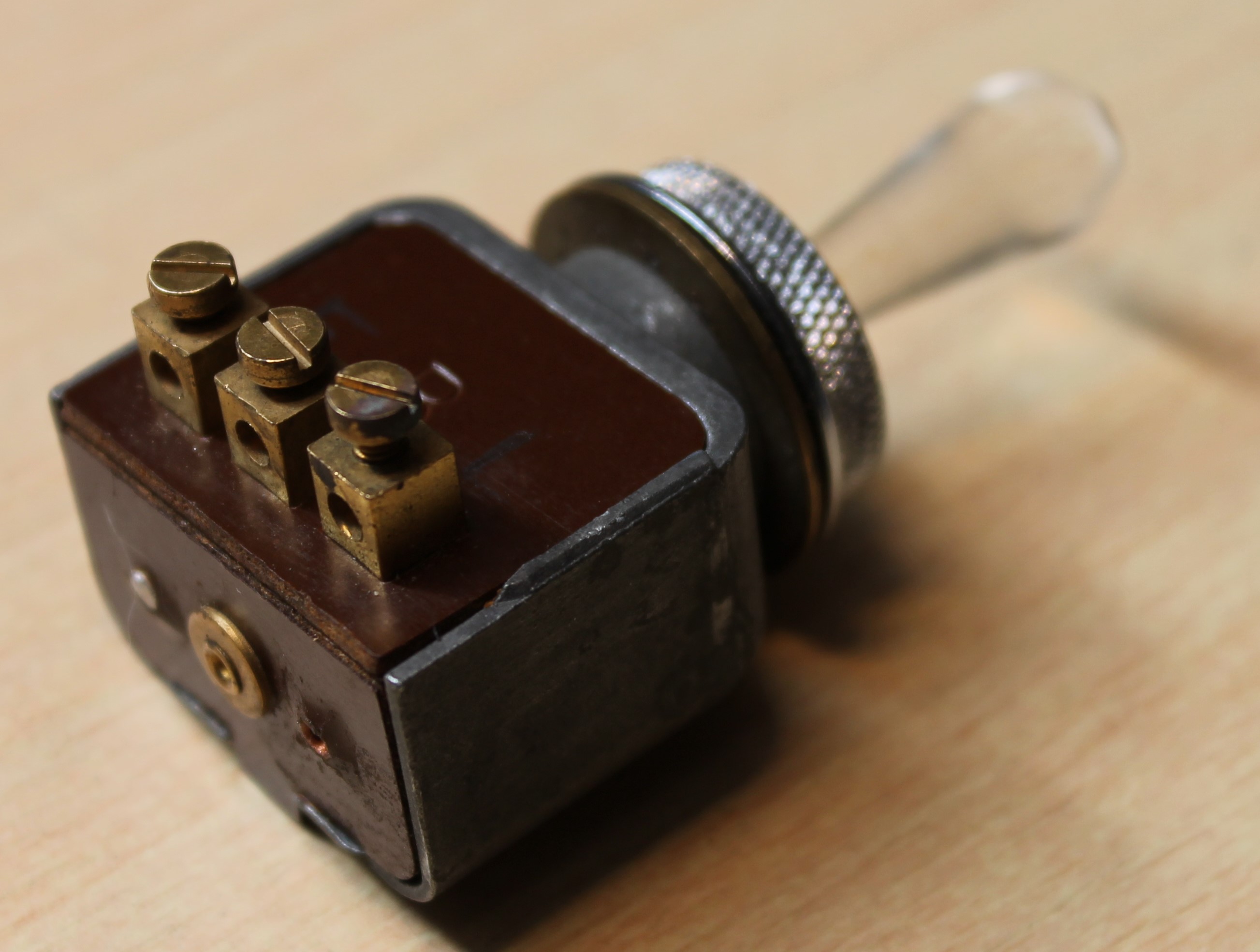
Trico manufactured different switches for automotive applications. Although they look very similar, there is a distinct difference in their functionality.
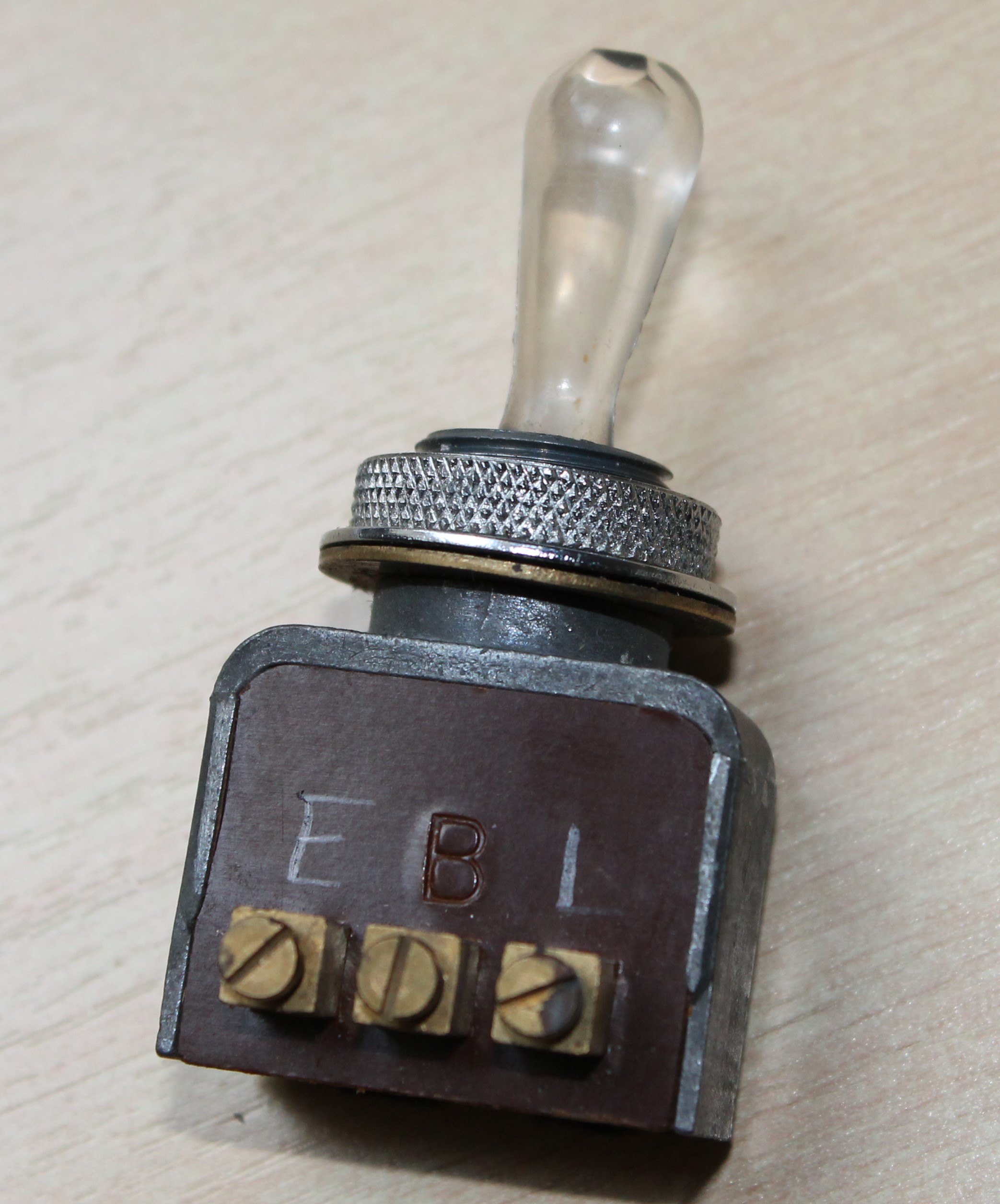
The Trico PS-33A switch was used as a direction indicator switch with 3 positions: left, off and right. This switch was used by a number of British car manufacturers and can sometimes still be found in NOS condition.
Jaguar used the Trico PS-4A switch as an overdrive switch from 1955 till the early Sixties. It is a two-position switch (on/off) but in fact largely identical to the aforementioned PS-33A as the internals of the switch are common.
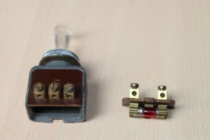 Trico PS-33A

The difference is that the warning light inside the switch has internal connections in case of the PS-4A, whereas the PS-33A has additional connectors on the bottom plate (which carries the warning light) but the correct internal connections for the warning light are missing. The way Trico made a two position switch from a three position is simply done by blocking the third position by using a rubber buffer that prevents the handle to move.
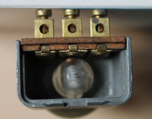
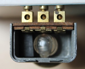 A rubber buffer is placed in the housing of the PS-33A to convert it to a 2-position switch


The PS-33A has only the letter B (for battery) positioned as an indication for the centre one of the three connectors on the phenolic back plate. It is easier to mark the other two contacts with E (for earth) and L (for “load” which in case of Jaguar is the solenoid of the overdrive).
 Marks for E and L in addition to the existing B
The conversions requires two modifications of the PS-33A switch:
1. After the bottom cover has been carefully removed it is possible to slide down the back wall of the switch. Beware of the ball that will jump out because of the spring behind it (see photo below right). A (semi-hard) rubber buffer of 12.7 x 10 x 7.0 mm is now placed (and preferably glued) in the aluminium housing at the side where the mark E has been put. This is done to block the third position. The 7.0 mm dimension is important and should be correct in order to allow the handle to rest in the centre position but not reach the third position.

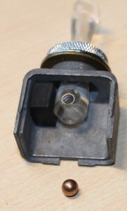 Rubber positioned

2. The warning light inside the PS-33A switch has two contacts. As the PS-4A has internal electrical connections, for the conversion external electrical connections have to be made to contacts E and L. The third contact B has an internal connection in case of the PS-33A but will not be used. There are two possibilities for making the electrical connections:
a. Simply connect the existing LH contact on the bottom plate to the E terminal of the back plate and the RH contact to the L terminal.
b. In case one would the PS-33A switch to look more like the PS-4A on the outside, then first remove the bottom plate and slide away the back plate (see photo above right). It is possible to (carefully!) remove the existing brass terminals on the bottom plate by pulling them out of the rivited brass connection. Then take two thin wires and solder them to the lamp contacts at each end of the bulb and connect one to the E and the other to the L connector on the inside of the switch.
 Internal connection made by soldering

The photo below shows the final result of the conversion (left) and an original PS-4A (right) for comparison.
Trico washer-pump malfunctioning and repair
Introduction
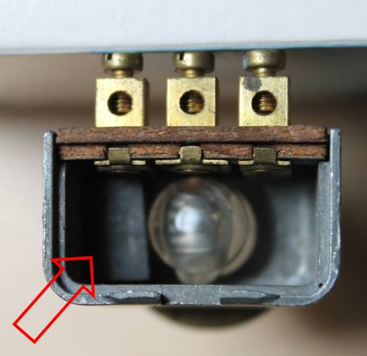
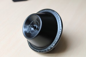
The vacuum operated Trico washer pump units are basically all identical, although the vacuum and washer fluid connections may differ. The pump unit of the XK 120/140 is placed on top of the glass reservoir whereas the pump unit of the XK 150 is placed within the glass reservoir.

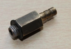
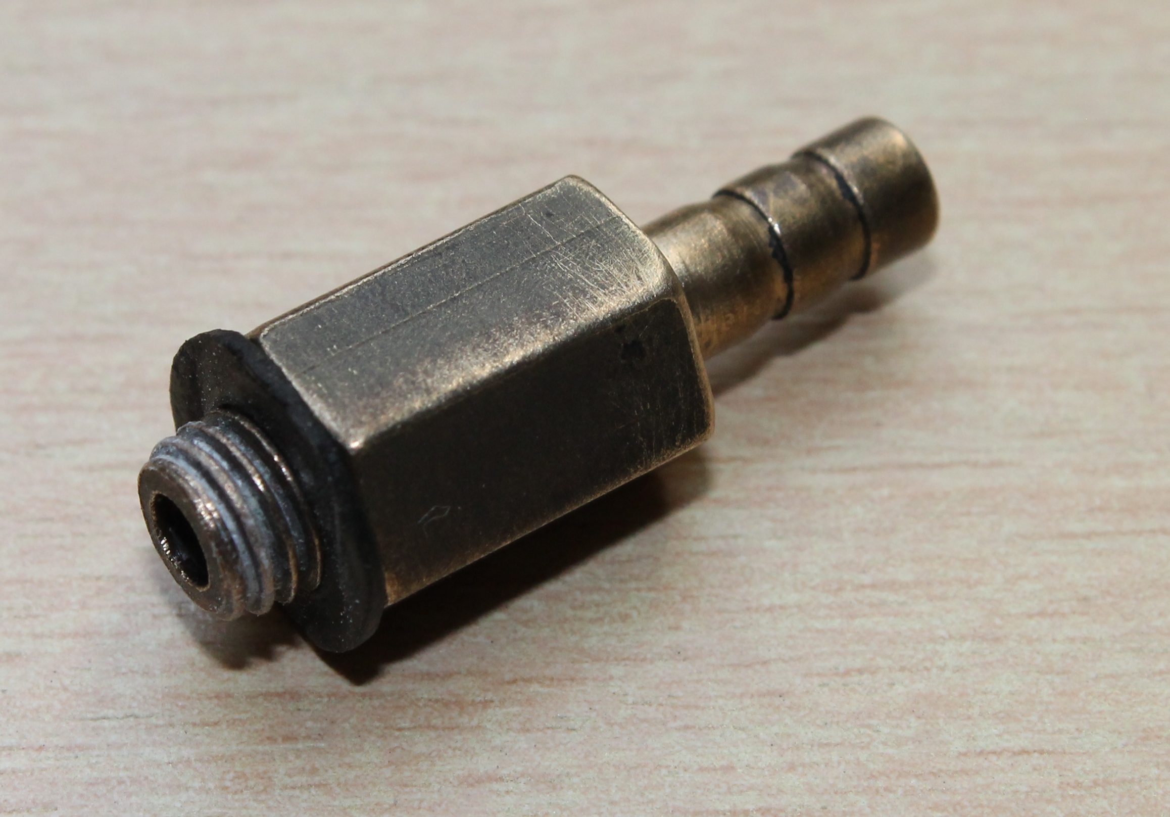
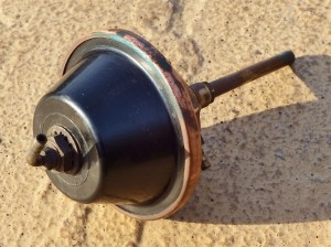 Pump XK 120 & 140: bottom fixation nut Pump unit XK 150 (& Mk 1) with fixation nut at the top

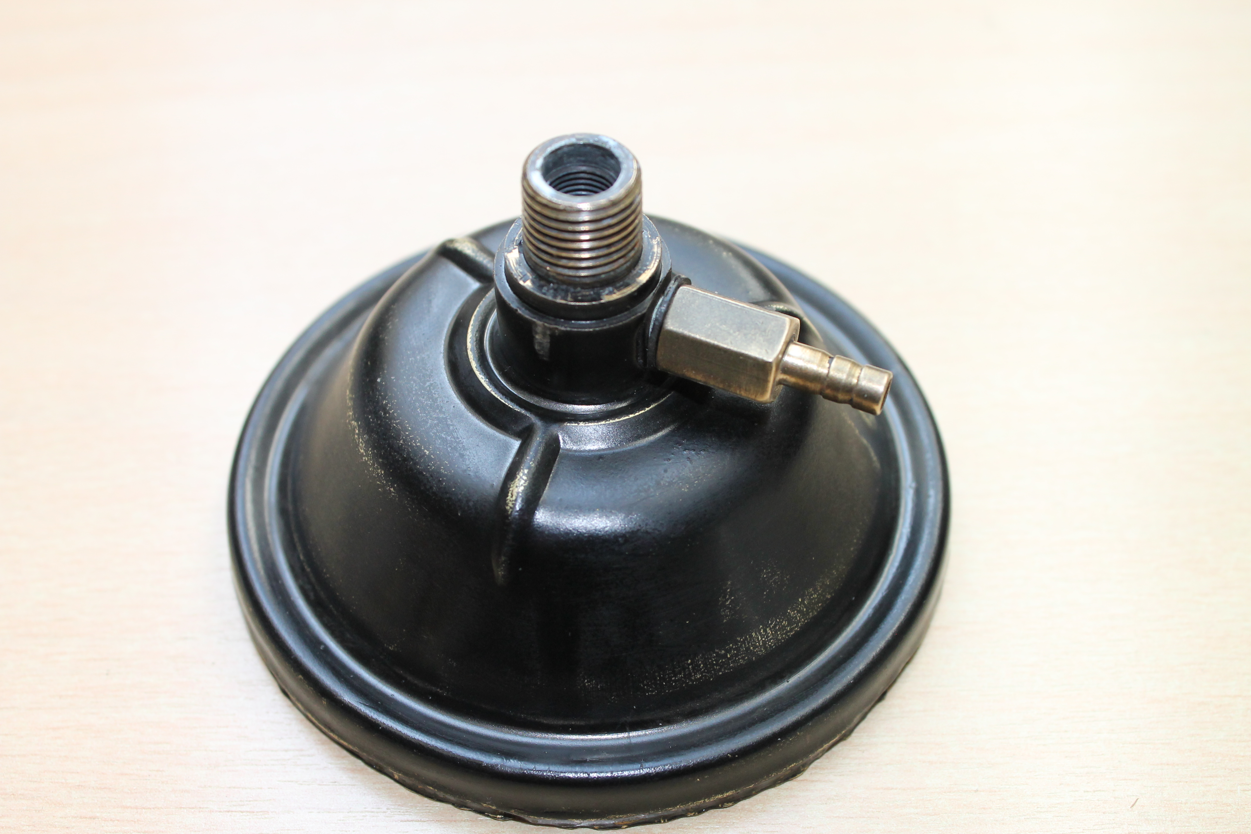
The pump of the XK 120 and XK 140 (Jaguar Part Nº C.5473/3 or Trico Part Nº X.82540) have a brass lower dome half (photo below left) and an upper half made of high pressure die-cast aluminium (photo below right). The XK 150 version basically has the same pump unit (Jaguar Part Nº C.10127/3) but with a different vacuum connection (on top) of the aluminium housing (see photo above right).
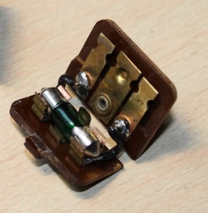
Over the years the rubber diaphragm will deteriorate, start leaking and eventually completely disintegrate: the pump has stopped working. See two examples below in different stages of disintegration.
Replacement rubber diaphragms are not available (yet?), but some have been manufactured on a small scale. Assuming a replacement diaphragm is there, it is possible to repair such a Trico pump under the condition that the other components can be reused.
Construction
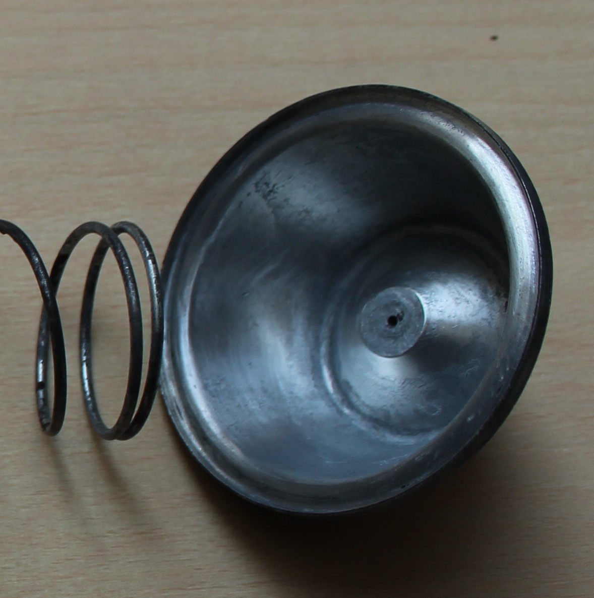
The two dome halves hold the rubber diaphragm (here shown in white but normally black). The diaphragm is pressed downwards in the brass part by a large spring. The rubber diaphragm has a brass “seat” to centre the spring at one side and a phenolic plate at the other side (see “exploded view” below).
This phenolic plate is pressed down by the large spring and in turn operates a small spring arm at the bottom of the brass lower dome-half when no vacuum is present. This small spring secures that the check valve in the suction tube is open and can suck washer fluid from the glass reservoir into the dome.
 Small arm operating check valve Second check valve in hose to washer jets

This check valve closes the “strainer” tube when vacuum is present above the diaphragm and prevents that water will flow back in the glass reservoir; this check valve consists of a steel ball and a spring . A second check valve is in the hose through which washer-fluid is pumped towards the washer jets. It is screwed in the side of the lower dome half and sealed with a fibre washer.
Repair step by step
It is possible (with a lot of patience) to open the rolled brass rim with a small screw driver. Try not to open the brass rim too quickly as otherwise the brass may tear or brake: take a small section and bend it open a liitle bit and then use a pair of pliers to bend the brass further to 90 degrees. Remember that there is a large spring inside, so keep both dome halves firmly together in your hand. The rubber diaphragm may have “glued” to the brass dome half and it may be required to separate the rubber from the brass using a screwdriver or chissel. Remove all parts as shown in the “exploded view”.
Clean all components and check for damage. Normally there is some corrosion on the inside of the dome that can be removed easily. Especially check whether the two surfaces that will hold the diaphragm are clean and smooth in order to obtain a perfect seal once the two dome halves have been “squeezed” together.
Place the components in the order as shown in the “exploded view” and note that the spring is rather long. Quite some pressure is therefore required to overcome the spring force and bring the two dome halves together.
It may be easier to make a special tool to hold the two dome halves under pressure while the edges are bent back to obtain a reliable mechanical seal.

 Simple tool to keep the dome halves together Finished product

Carefully bent the brass rim back to a flat position, trying not to use excessive force from e.g. a steel hammer since this would stretch the brass (instead of shrink it). We may assume that Trico used special equipment to roll back the brass rim and we should try to come as close as we can to this mechanical operation (with simple hand tools). It is possible to obtain a good seal, although signs of the operation will remain visible (photo above right).
End result
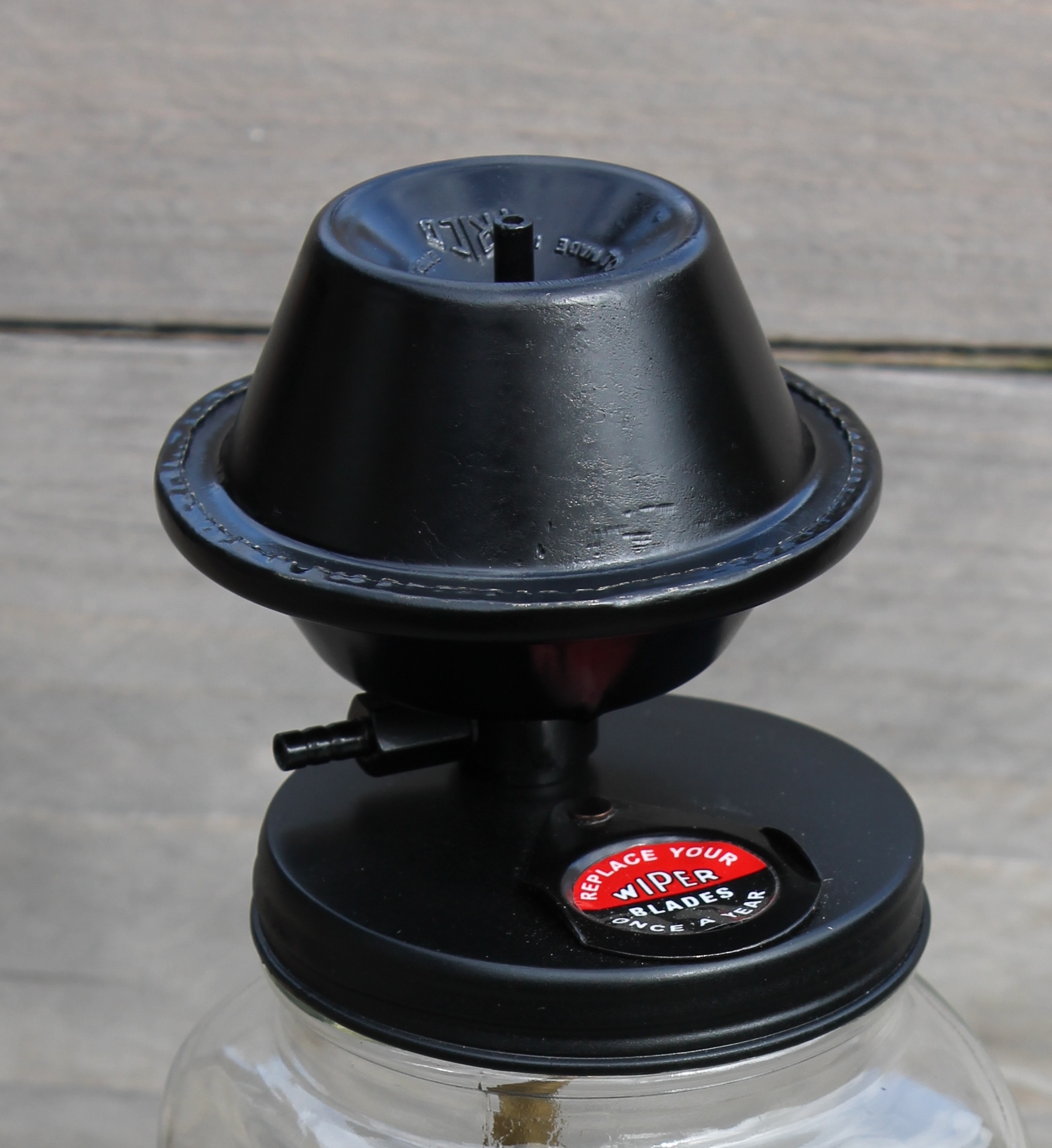
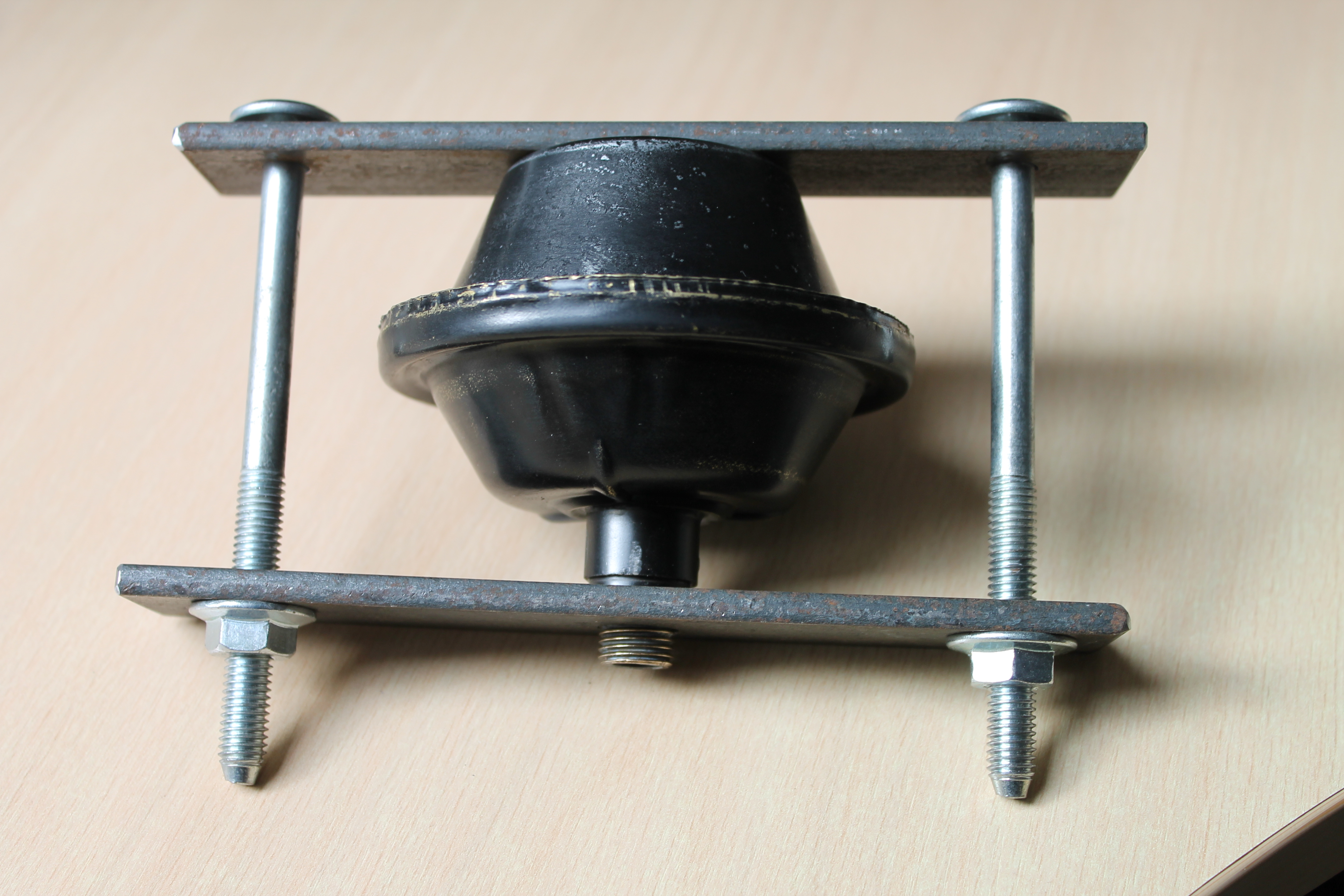
It is very rewarding to see a 60 year old defective washer pump fully operational again. Complete washer pumps are available nowadays but they are rather expensive and may deviate from the original Trico design of the 1950’s: the XK 150 upper dome is sometimes also used for the XK 120/140 versions. Shown here is the “repaired” XK 140 FHC washer unit with the square bottle.
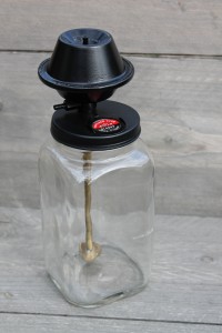 Original XK 140 FHC Trico washer unit: fully functional

Derrington steering wheels 1950’s
Derrington steering wheels for 1950’s Jaguars
This article attempts to summarise (in a structured way) information published on the subject of Derrington steering wheels, gathered from various sources.
Chapter 1 The Derrington company
V.W. Derrington Ltd. has been established around 1919 in New Malden, Surrey, England (about 12 miles south-east of London) initially tuning motor cycles of that era. By 1926 they moved to nearby Kingston and became successful in developing and supplying tuning components like manifolds, exhaust pipes, cylinder heads, and other mechanical improvements for automobiles as well as luggage carriers. From 1933 onwards Derrington advertised with steering wheels as part of their business activities.
Victor William Derrington had been a (motorcycle and automobile) race driver himself for many years, allowing him to exploit his racing experience for developing tuning equipment.
After WW2 there were two “fast runners” made at the Derrington works at London Road in Kingston: Derrington luggage racks and Derrington wooden steering wheels available for many models of the 1950’s and 1960’s. According to “Motor Sport” magazine of December 1959, Derrington employed at that moment eight people full time in the production of steering wheels.
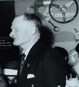 Vic Derrington at the 1961 Racing Car Show; note steering wheel at display

Note that over 60% of Derringtons production was exported, the majority to America. The steering wheels were especially popular in the States and several hundreds have been exported every year from about 1953 onwards. Orders for the USA could only be supplied through their West and East Coast agents: Vilem B. Haan in Los Angeles (CA) and Wilco of Rochester (NY).
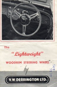 Front of a 1960 brochure

Chapter 2 The “Derrington wheel” and similar wheels
Although Derrington made steering wheels with various spoke configurations, the company became famous for one particular model that we now call the “Derrington wheel”. The specification of (and additional information on) the “Derrington wheel” is provided in Chapter 3.
As production volume increased, Derrington started to outsource some of the steering wheel activities. By the end of the 1950’s another steering wheel manufacturing company Moto-Lita was capable of providing “Derrington” steering wheels, however it is believed that Moto-Lita made wheels in those days were not of the same high quality as Derrington manufactured wheels.
We may assume that Derrington gradually moved away from steering wheel production, fully concentrating on their successful tuning activities. Probably in the late 60’s Derrington completely ceased their steering wheel production activities and Moto-Lita continued the manufacturing of the typical “Derrington wheel” however always characterised by their standard nine hole centre mounting (see Chapter 4).
A similar wheel was offered by the Donald Healey company for their (Austin-Healey) sports cars, which may lead to confusion. This wheel is therefore further described in Chapter 5.
Finally, the name Derrington is often linked to a Jaguar woodrim steering wheel that was available as an option for the Mk 2. However, this was not the “Derrington wheel” but a different model as is described in Chapter 6.
This brings us to the following timeline for the Derrington (style) wheel:
- 1953/54 onwards: the “Derrington wheel” manufactured by Derrington in 15, 16 and 17” diameter
- 1955 onwards: Donald Healey manufactured “Derrington style” steering wheels
- 1959/60 onwards: Moto-Lita manufactured wheels for Derrington (and Donald Healey)
- 1960 onwards: Jaguar Mk 2 Derrington steering wheels (different style with non slotted spokes)
Chapter 3 The “Derrington wheel” specification
Around 1953/1954 Derrington started the manufacture and delivery of the “Derrington wheel”. The design itself shows some resemblance to an earlier Italian manufactured Nardi model with three slotted spokes, however not with the characteristically 3 x 120° even spacing of the Derrington wheel.
Derrington had a patent applied for the making of wooden steering wheels on October 18, 1954 and granted on October 5, 1955.
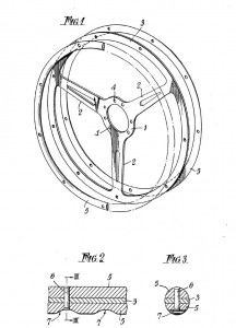 Original patent application of October 18, 1954

Specification and characteristics of the original “Derrington wheel”:
- three (slotted) “Birmabright” aluminium spokes with even (3 x 120°) spacing
- flat (non-dished) version
- eight-hole centre mounting with 8 flat CSK slotted screws and nuts (BSF 3/16 – 32 ?)
- laminated rim from mahogany and either obeechi or white sycamore
- (nine or) twelve rivets in the laminated rim
The “Derrington wheel” was standard delivered in 16″ diameter, but 15″ and 17″ versions were available to special order. There are also examples of original Derrington manufactured wheels that had a 9 hole centre mounting.
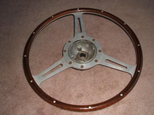
 Original Derrington 16” wheel with 8 screw mounting and 12 rivets.
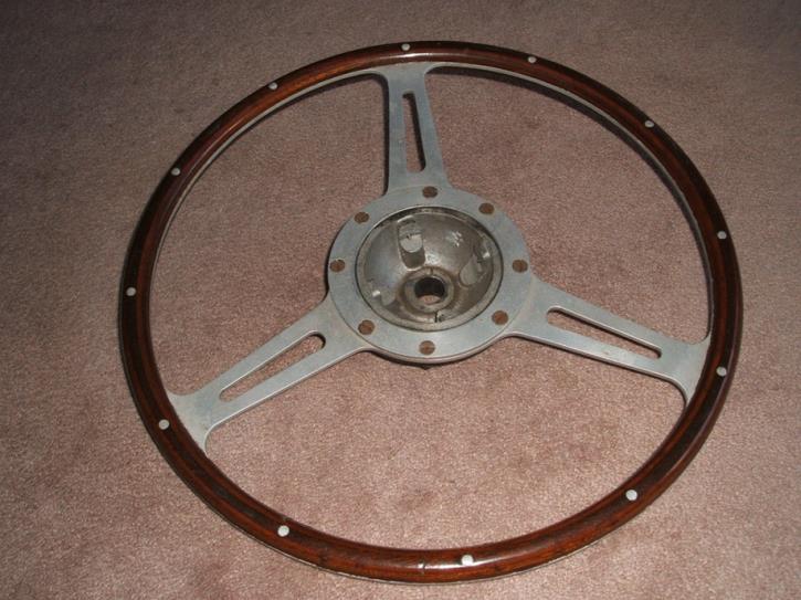
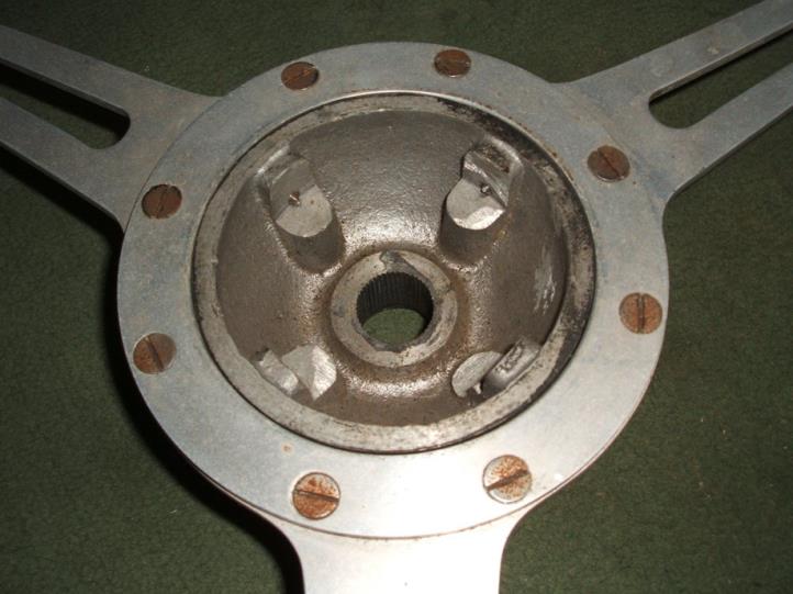
The frames of the wheels were cut from Birmabright (an alloy of aluminium and magnesium with 7% magnesium and 1% manganese; also known as BS NS4, American 5251 and ISO AlMg2), and the laminated wooden rims were riveted to the frame. The laminated woodrim consisted of African Obechi wood and Mahogany. The boss (or hub) is cast from aluminium (mostly LM6) and machined to fit each particular model.
There have been many discussions over the past decades, whether this Derrington wheel was a genuine Jaguar factory option or not. Although apparently more was possible at Jaguars (including a “Bluemels wood rim steering wheel”) than one would understand from the “optional extras” 1958 list, the general opinion is that wooden steering wheels were not available as a factory option, until around 1960 when Jaguar offered a wooden steering wheel for the Mk2 (part number C.25198), but we know that this is actually not the even spaced “Derrington wheel”. Part number C.25198 is mentioned in spare parts bulletins and parts catalogues as well.
We also know that the “Derrington wheel” was rather popular in the 1950’s and was advertised in many car magazines, including those in the USA. Reference is made of the June 1960 issue of Sports Car Illustrated containing ads for the “Well Known Derrington Racing Steering Wheel”. We referred already to the two US Derrington importers, which indicates that Derrington wheels were freely available in the USA. So therefore we may assume that a (large?) number of XK’s may have received an aftermarket Derrington wheel in the 1950’s. Whether or not there was any “active support” from Jaguar USA in supplying these steering wheels remains unclear. Dealers however may have recommended these Derrington wheels themselves in order to increase sales.
 Early Derrington wheel with 8 screw mounting.
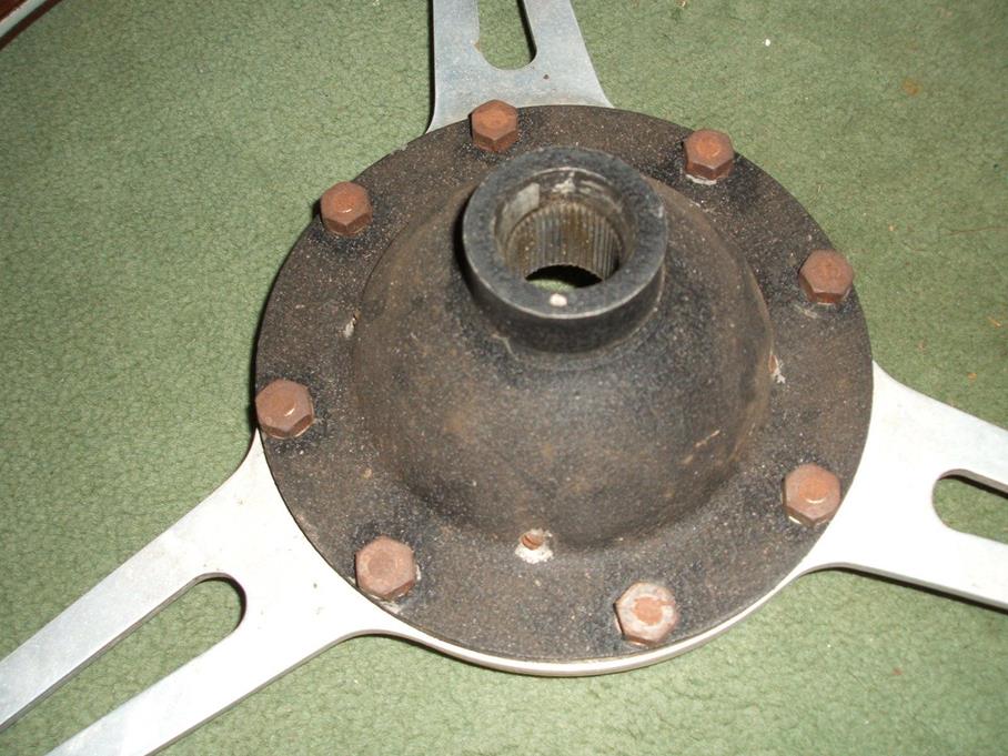
The Derrington brochure (shown below, probably dated 1960) not only lists the prices in Pound Sterling but also in US Dollar, which further supports the active marketing policy of Derrington in the USA. Also note the text in the brochure that “practically the entire output for the past few years having been exported”. This may further clarify the presence of Derrington wheels on US Jaguar XK 120, 140 and 150 in the 1950’s.
The list with (only European) car brands and types in the Derrington brochure is long and all Jaguar versions from the period 1950 to 1960 have been listed.
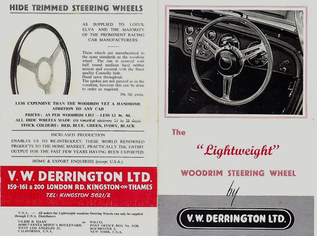
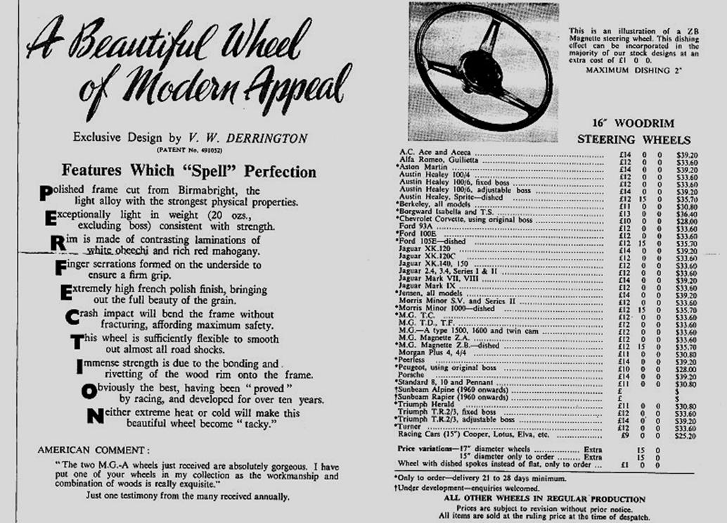
Chapter 4 Moto-Lita manufactured wheels for Derrington (~ 1960 onwards)
Around 1959 Moto-Lita started making steering wheels for Derrington including the famous “Derrington wheel”. Some say that Moto-Lita made wheels of that era were not of the same high quality as Derrington manufactured wheels. Moto-Lita continued the use of 12 rivets but it is unclear whether Moto-Lita was requested to continue the use of 8 bolt centre mounting or that these wheels immediately switched over to the 9 bolt centre mounting boss/hub as already made by Moto-Lita.

Above is a photo of a 1960’s Derrington wheel made by Moto-Lita. Diameter is 16 inches. It uses the Moto-Lita style hub with 9 screws. Moto-Lita still manufactures the “Derrington wheel” today and adheres to the original design although with 9 bolt centre mounting (see photo below).
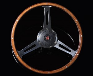 Modern Moto-Lita “Derrington wheel”
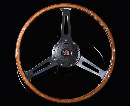
Chapter 5 Donald Healey manufactured “Derrington style” steering wheels (~ 1955 onwards)
The story goes that Donald Healey aimed at in-house production of 16” woodrim steering wheels for the Austin Healey 100 series. The designs were made by Gerry Coker and the first models were manufactured in-house. There were in fact two designs: one with drilled and one with slotted spokes. The latter has a very close resemblance to the “Derrington wheel” with even spaced spokes.
These first versions (also used on the AH 100 Le Mans cars) were made of six separate solid wood segments (not laminated) fixed to the aluminium frame by 4 rivets for each of the 6 per segments (so 24 rivets in total). They had a 9 bolt centre mounting (like Moto-Lita).
 Original AH 100 Le Mans “segmented” wheel with 9 screws and 24 rivets in “Derrington” style
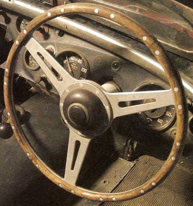
The AH 100M could be delivered with the slotted spoke version as a factory option. These wheels were no longer made by Donald Healey but manufactured by the Coventry Timber Bending Co. Ltd . The Coventry Timber Bending Company was a manufacturer of “laminated and solid wood work for cars and boats”. The company had been established in 1938 by their directors: H. E. Newsum and L. G. Hains. They started activities at Swallow Road, Holbrook Lane in Coventry, but later moved to new premises about 5 miles to the east, at Bodmin Road, Walsgrave, also in Coventry. In 1954 they also produced the D-Type Jaguar steering wheel and from 1961 produced the E-Type steering wheel as well. In 1984 the company became Insolvent and was wound up.
The Coventry Timber Bending Co. manufactured “Derrington style” woodrims were made of beech and had only six rivets to fix the wood. The aluminium frame was initially riveted (not bolted) to the boss.
(See for more info: Autocar of December 2, 1962)
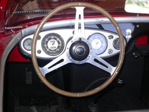 Strong resemblance, but not Derrington!
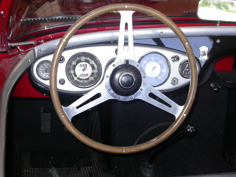
The steering wheel with drilled spokes became the standard wheel on the 100S production cars.
Around 1960 Moto-Lita began to supply “Derrington” style steering wheels to Healey, which now had 18 rivets instead of 24 for the in-house manufactured versions or instead of 6 as made by Coventry Timber Bending. These Moto-Lita steering wheels were Healey badged (or stickered).
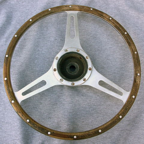
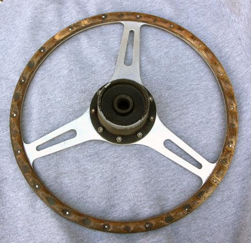
Most likely the above photos show the later Moto-Lita made “Derrington wheels” supplied to Donald Healey with 9 screw mounting and 18 rivets! The 6 segment solid wood method has been replaced by a laminated circular construction.
Chapter 6 Jaguar Mk 2 Derrington steering wheels (different style with non-slotted spokes)
Jaguar, possibly aware of the lively interest in woodrim steering wheels, offered a special 17-inch lightweight, wood-rim steering wheel manufactured by Derrington. It seems that this version was manufactured at the explicit request of Jaguar for use to special order on Mk 2 cars.
![]()
The Birmabright spokes had been polished and the woodrim of contrasting laminations of white obeechi and rich red mahogany were clear lacquered to bring out the grain. The Jaguar wheel was priced at £12 and it takes the standard Jaguar Mk 2 half horn-ring.
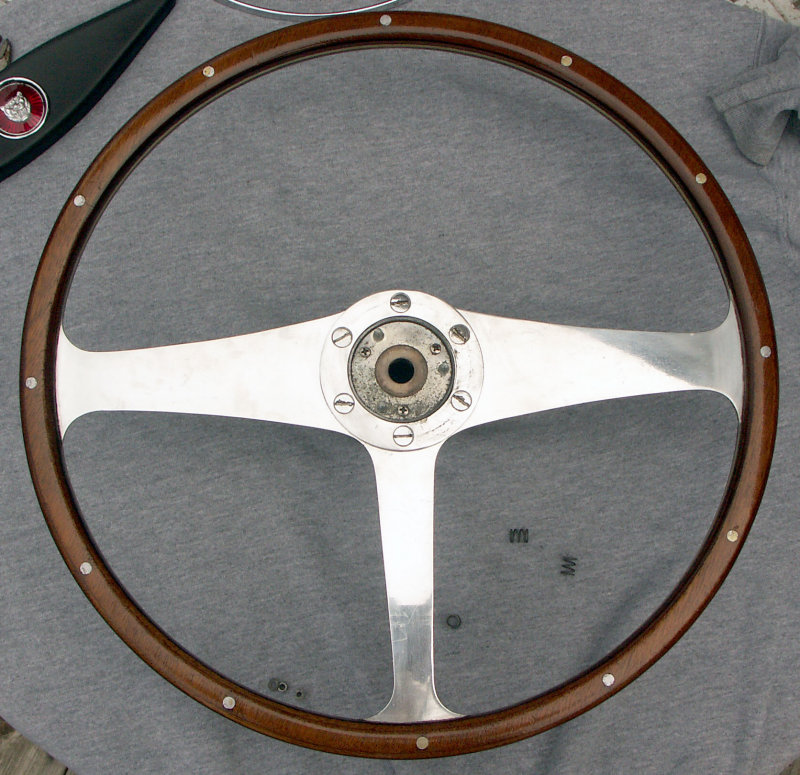

Lucas wing mirrors on Jaguar (’45 to ’70)
Potential suppliers of wing (fender) mirrors
Known for their electrical equipment, Lucas also had a large range of rear view mirrors in their programme from the 1930s onwards. It is therefore logical that Jaguar first had a look at the Lucas mirror portfolio. Next to Lucas there were a large number of other (pre-war) mirror manufacturers like Wingard, Magnatex (TEX), Raydyot, Desmo, and many others. We have to note that in the 1940s and 1950s there were many countries without a legal obligation to have exterior mirrors and therefore these mirrors were only offered as an “optional extra” or even to be purchased by the owner as an aftermarket product. In (some states of) the USA, however, it was necessary to have one exterior mirror mounted at the driver side.
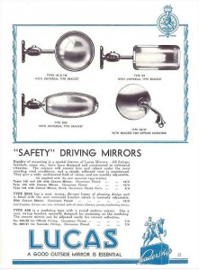 1937 Lucas catalogue; note that Lucas 406 mirror dates from 1937

Wing (fender) mirrors for Jaguars: the 406 series with convex glass.
“First generation” Lucas 406
In the mid-Thirties Lucas introduced the “Lucas 406 exterior mirror for mud-wing mounting” which was available as Nearside and Offside version. The 1939 Lucas Catalogue 400B refers to an outer diameter of 4 3/16 inch or 106 mm and lists the following part numbers:
406/29-OS 580.733 406/41-NS 580.736
The Lucas 406 series exterior mirror is mounted with a single bolt (5/16” BSF) through the front wing. It has a chromium plated round mirror head, and was available with convex glass only. The mirror head is adjustable and is secured by a clamp using 3 screws. This implies that all Jaguars manufactured before the mid sixties could have convex mirrors only. Flat glass mirrors are a later addition or replacement.
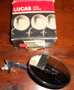 Original 406/29 convex glass mirror and box

The Jaguar Mark V parts catalogue lists the Lucas 406 mirror 580733/A for RHD and 580736/A for LHD. Apparently only one side was supposed to get a mirror installed on the wing above the front wheel. We also find the description (supporting this) that some Jaguars only had an “O/S mirror” (off side or passenger side).
The RH(D) mirror Lucas part number 580733 is known as Lucas model 406/29: this a chromium plated 4¼” round exterior mirror with mounting Bracket 620783. Similarly, LH(D) mirror Lucas part number 580736 is Lucas model 406/41 and is fully identical apart from the Bracket, now part number 620784: the two brackets are “handed”. Note that the indication /29 and /41 relate to the type of Bracket used; this number is also found on the base of the brackets.
The Jaguar XK120 didn’t have the (factory) option to order exterior (wing) mirrors, but there are sufficient photos around to proof that the Lucas 406 mirror was used on the XK120. The most famous is possibly NUB120 which had the first generation Lucas 406/29 and 406/41 from 1950 onwards.
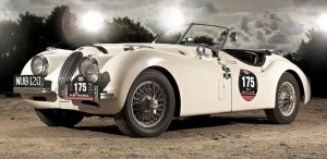 NUB 120 with early Lucas 406 mirror

Please note that on NUB 120:
- The mirrors have been switched: the RH mirror is now on the LH side, possibly in an attempt to keep the mirrors within the maximum width of the car.
- The mirrors have been placed much closer to the driver and not on the top of the wing above the front wheels as later XKs normally have.
“Second generation” Lucas 406
Early 1953 Lucas introduced an improved version of the 406 series, which was indicated by adding suffixes to the Model number and by a new part number:
- Model 406/29 became 406/1/29A with new Lucas part number 062587.
- Model 406/41 became 406/1/41A with new Lucas part number 062590.
Note that the mounting Bracket (or stem) did not change with the new version and remained 620783 for RH and 620784 for LH.
As mentioned before all 406 mirrors originally had convex mirror glass, meaning the viewing angle was larger but the reflected image itself smaller. Later a flat glass version was added to the range.
The Lucas “Advance Information” catalogue for 1955 jaguar Cars (issued February 1955) mentiones these newer 406 mirrors (Lucas 062587 and 062590) for the Jaguar Mk VII, but “Export only”. The corresponding Jaguar part number is C9091 (with a rubber pad C9904 for the fitting). As stated, initially only as an option for (export) Mk VIIs but later as standard fitment for the Jaguar Mk VIIM.
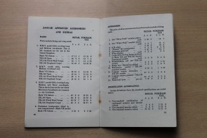 “Salesman’s Data Book” XK 140 listing wing mirrors
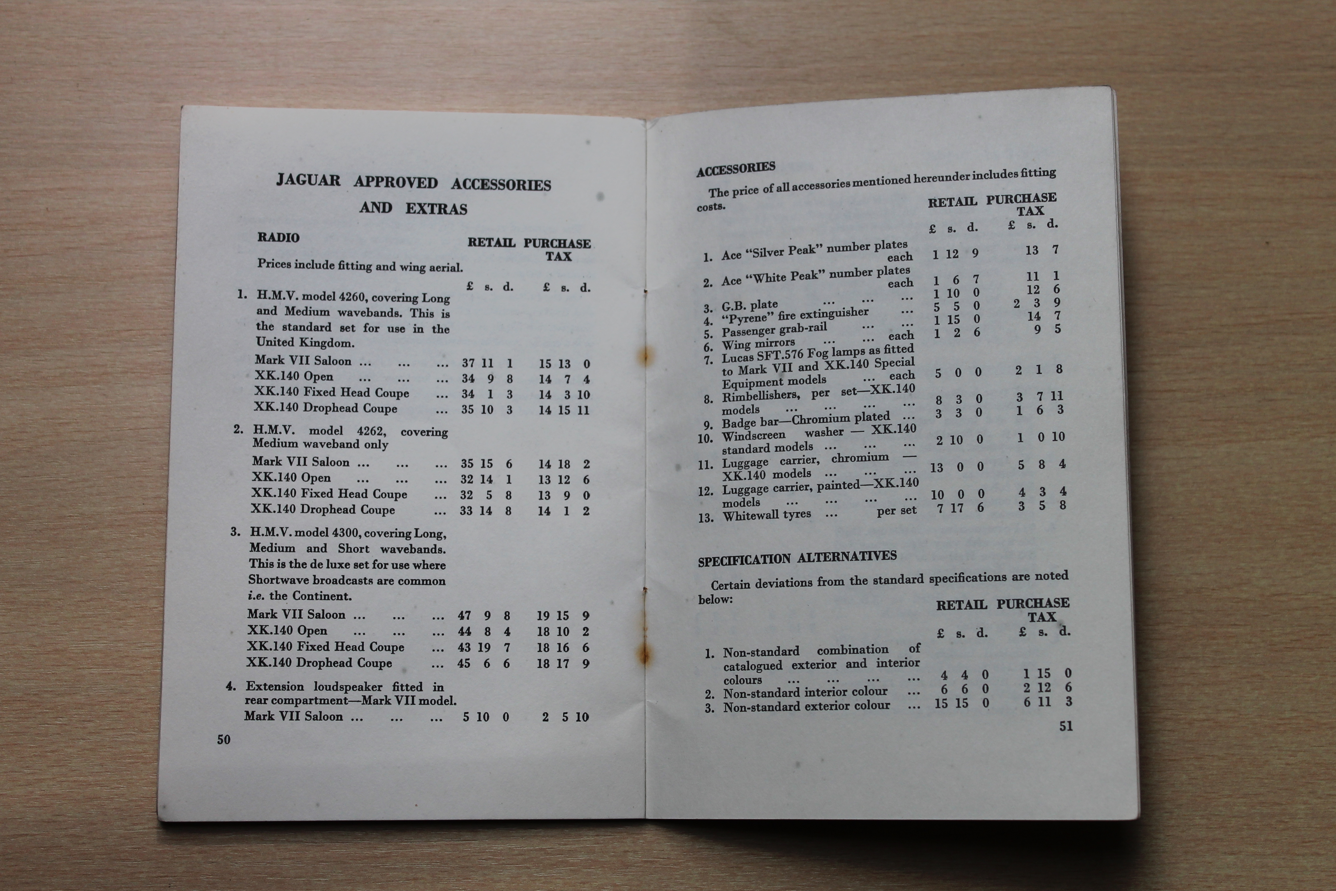
According the Spare Parts Catalogue the XK140 still didn’t have the (factory) option to order exterior (wing) mirrors. But the 1955 “Salesman’s Data Book” for the XK140 (and Mark VII M) clearly states that wing mirrors were available as “Jaguar Approved Accessories and Extras”. Also some photos from the mid 50s show XKs with either a single (driver side) or double wing mirrors. Dealers may have also ordered spare Mk VII wing mirrors (C9091) and holes were drilled to mount them.
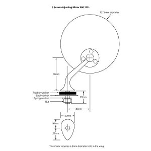 Lucas 406 mirror dimensions

Technical details of the Lucas 406 range (second generation 1953 onwards)
- Lucas wing mirror RH Model 406/1/29A Part number 062587
- Lucas wing mirror LH Model 406/1/41A Part number 062590
- Mirror head 406/1 Part number 62540A stamped on mounting flange
 Original 406/1 65240A three screw mirror head
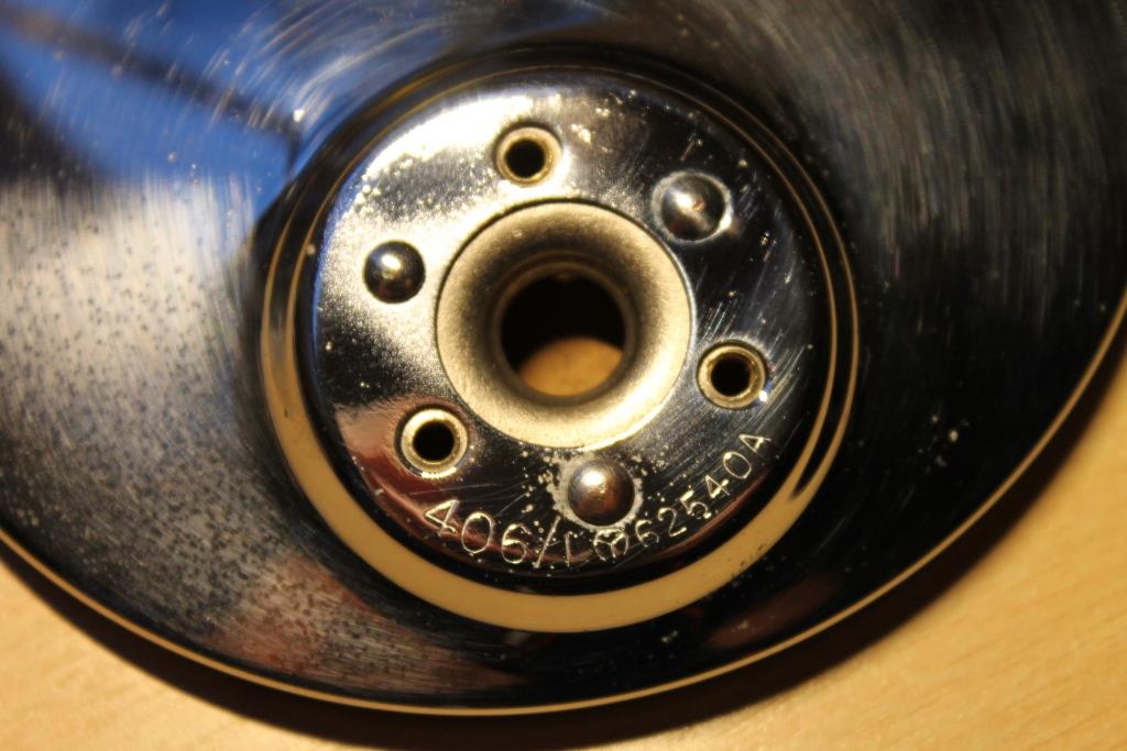
- Screw, ball clamping fixing Part number 655453 (3 pcs) RCSK slotted chromed 4BA x ½”
- Ball clamp (stamped “Lucas Made in England”) Part number 620786
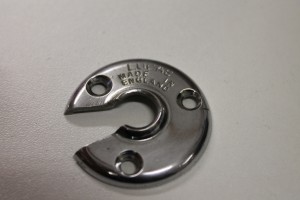 Original ball clamp

- Bracket assembly RH Part number 621740
- Bracket assembly LH Part number 621749
- Nut (BSF5/16 x 22), brass cadmium plated, fixing mirror to wing Part number 182519
- Washer shake proof for Nut 182519 Part number 188471
- Washer, plain, OD 1½ “, under wing Part number 580735
- Pad, rubber, base Part number 580734
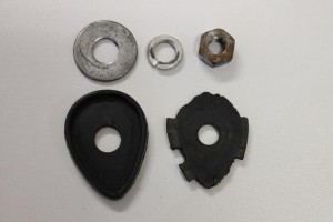 Text on original rubber pad: LEW 16

- Bracket RH Part number 620783
- Bracket LH Part number 620784
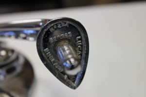
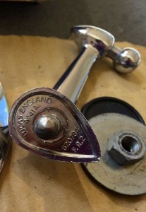 Note the Bracket models numbers 29A and 41A next to the part numbers casted in the base.
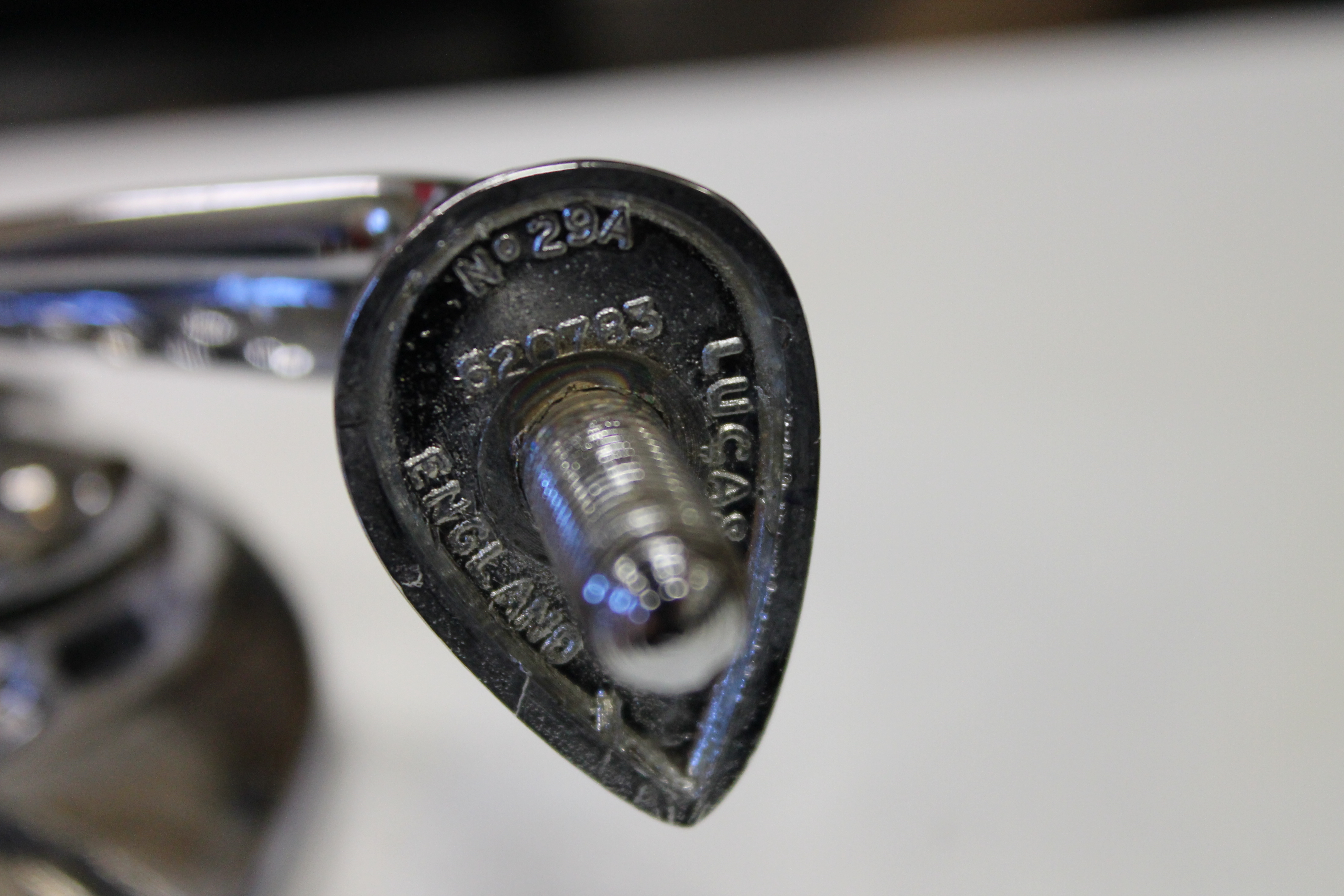
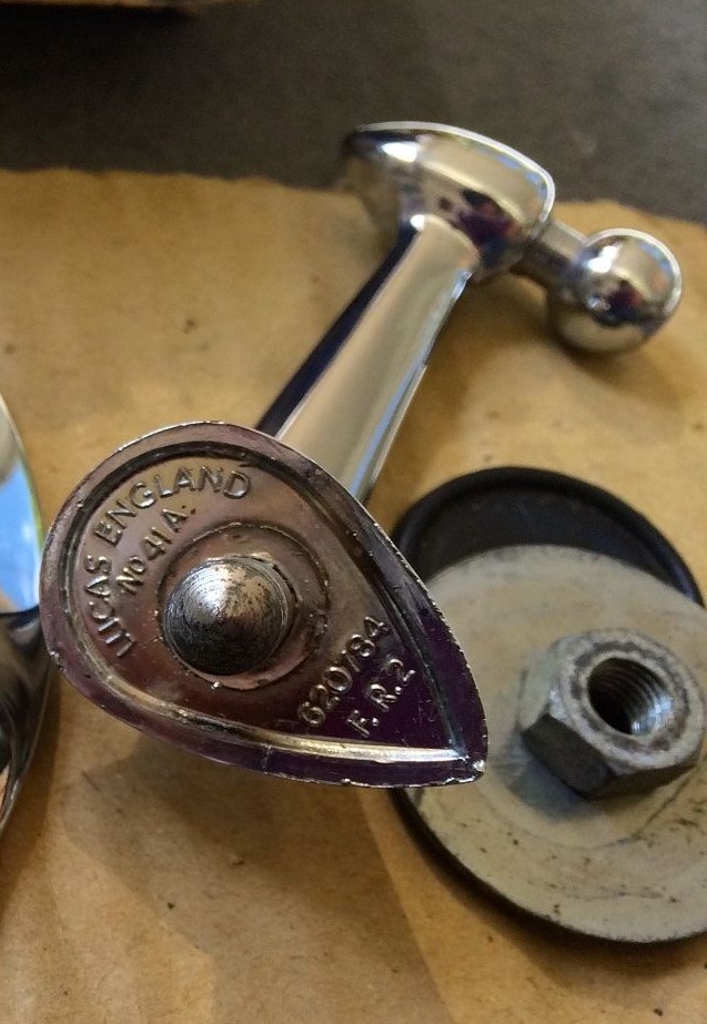
The mirror glass is held in the chromed mirror head by folding the outer rim over the glass (in a rotational process). The glass is sealed by a rubber ring and backed by thick paper. See photo.
 Photo Tadeusz Malkiewicz
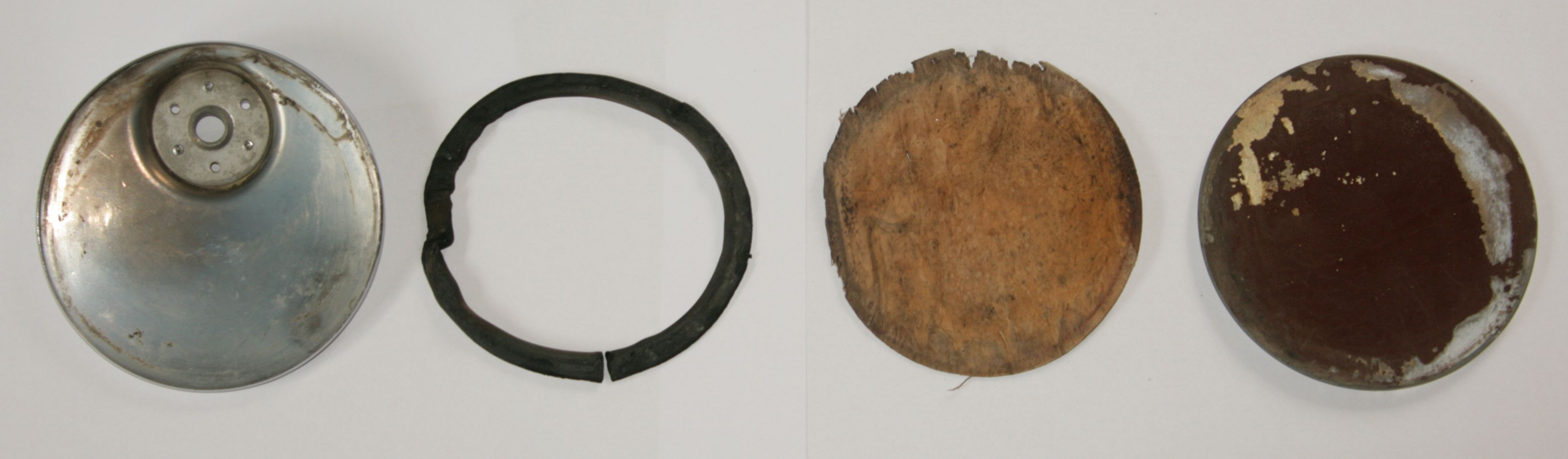
Addition of flat glass mirrors: the Lucas 407 range
Late 1959 or early 1960 a flat glass range was added next to the model 406. The new versions were 407/29 (for RH) and 407/41 for LH mirrors. Also note that the Lucas part number was no longer stamped on the mirror head. A complete survey of 1967 Lucas catalogue numbers under the chapter “Recommended Accessories”:
- Model number 406/29 (RH) convex glass: 59061047
- Model number 406/41 (LH) convex glass: 59061049
- Model number 407/29 (RH) flat glass: 59061055
- Model number 407/41 (LH) flat glass: 59061056
- Model number 407 (LH=RH) flat glass 59061057 (see next paragraph)

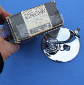 New box for 407/29 (59061055) flat glass mirror Lucas 407/41 (59061056) flat glass mirror
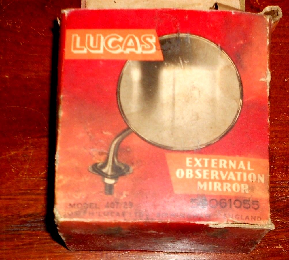

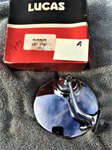
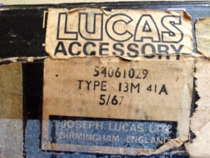 Lucas 59061047 LH Convex mirror Lucas 407/41A but other code 54061029

- “Third generation” Lucas 407/112; symmetrical two screw mounting
This version was introduced late 1959 or early 1960. It is based on the (new) flat glass 407 mirror head but received a new bracket (Lucas 112) that could be used both left and right . This model was about 15% cheaper than the 406 or 40729 and 407/41 models, that remained however in the programme. Some Jaguar XK150s and some E-types have been seen with these mirrors from new, but it is unclear whether this is a factory (optional extra) mounted version or a later addition.
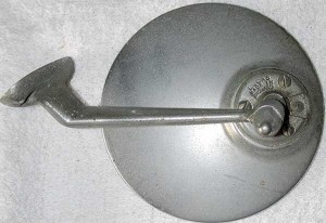
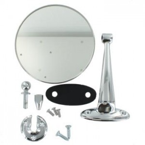 Lucas 407/112

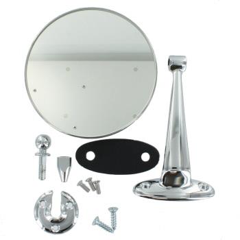
The change implied a new type of Bracket (Lucas 112) which was now mounted on wing, pillar or door using 2 self-tapping screws instead of the single larger (5/16”) bolt of the previous two generations. This change necessitated a different base to create sufficient space for the two screws. This mirror is indicated as Model 407/112 and the part number for the complete mirror is 59061057 (dated 1967). The Bracket Lucas 112 has part number 521545 and “BS 1004A” casted in the base (the latter being the early British Standard for “Specification for zinc alloys for die casting”). Model 407/112 was never offered with a convex mirror head, also because now the mirror could be mounted closer to the driver. The way the mirror had to be adjusted remained the same.

 Later model 407/112 flat glass mirror with symmetrical base and 2 screw mount; Lucas 59061057
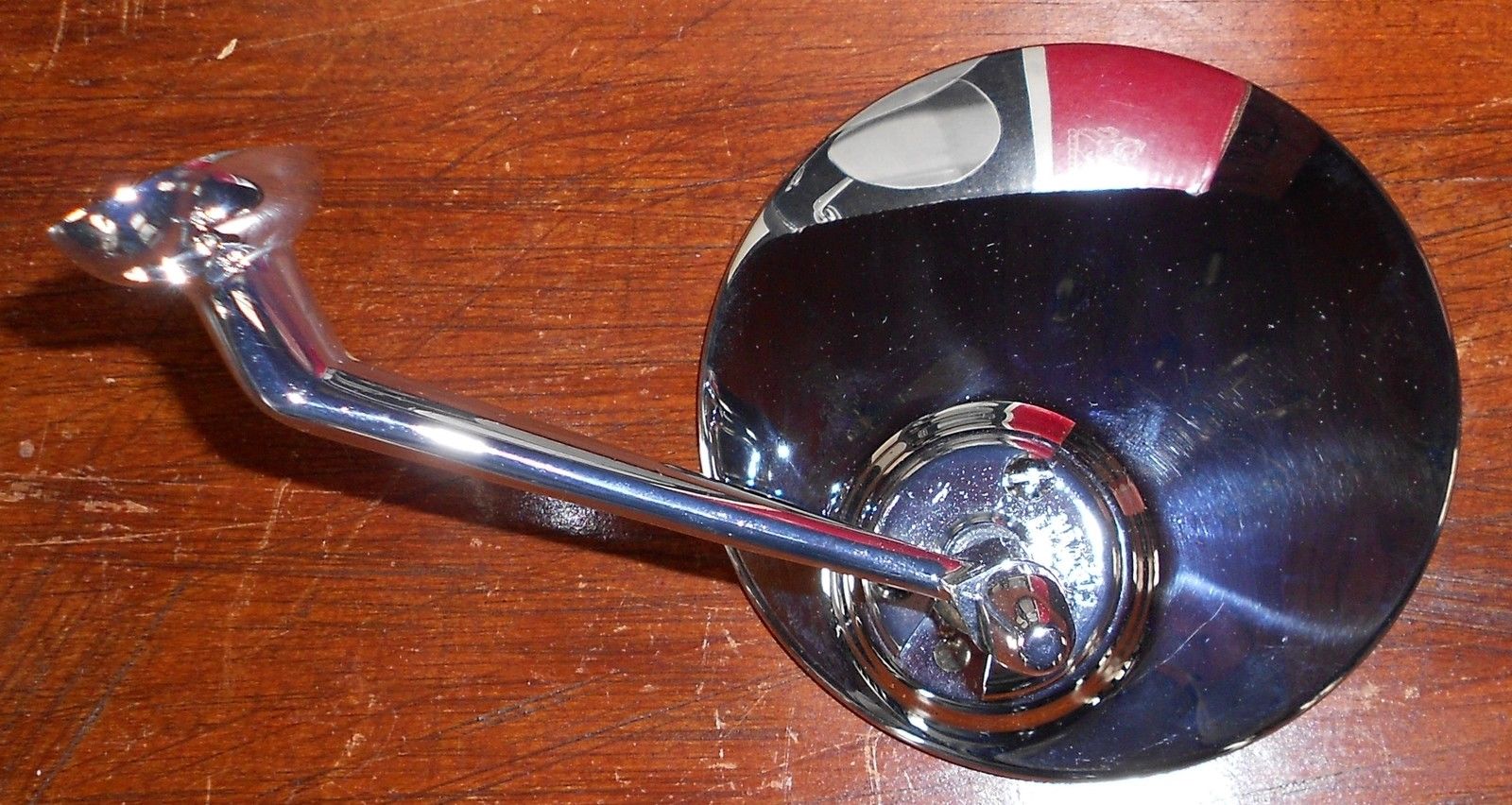
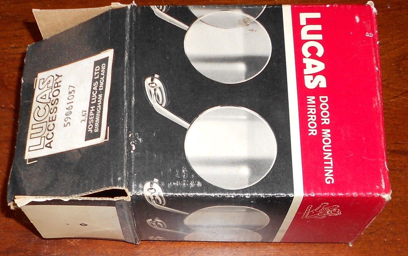
The C.9091 (the “second generation” 406, made by Lucas) was most likely initially continued when the XK150 was introduced in 1957. For the first time the wing mirror was included in the Spare Parts Catalogue as an “optional extra” that could be ordered from the factory. The XK 150 Spare Parts Catalogue mentiones part number C.16114 for the wing mirrors; this may refer to the modified Lucas model 407/112 with Lucas part number 59061057 (see above) as supplied from 1959/1960.
This (third generation) Lucas mirror type is also seen on (Series 1) E Types, although TEX mirror types may have been used as well around that time.
Other Lucas wing mirrors
Characteristically the Lucas 406/407 type of mirrors all used a 3 screw clamp for mounting the mirror head to the bracket/stem. As we have seen above, different brackets have been added to the programme (see also example “third generation”) but we have seen more bracket versions: see unknown example below. Model number unknown.
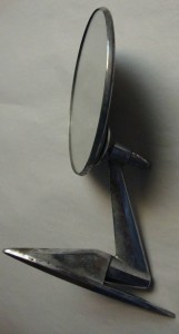 Unknown Lucas model number
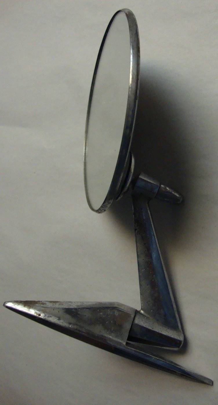
Years later (1970s) Lucas switched over to a new mirror head fixation (MH 3) with a single bolt permanently attached to the mirror head. These mirror heads are no longer interchangeable with the 406 kind of mirror heads. This fixation system is more or less identical to e.g. the TEX system. The convex mirror head was coded MH 3C and we may assume that the flat mirror was coded MH 3F (unconfirmed).
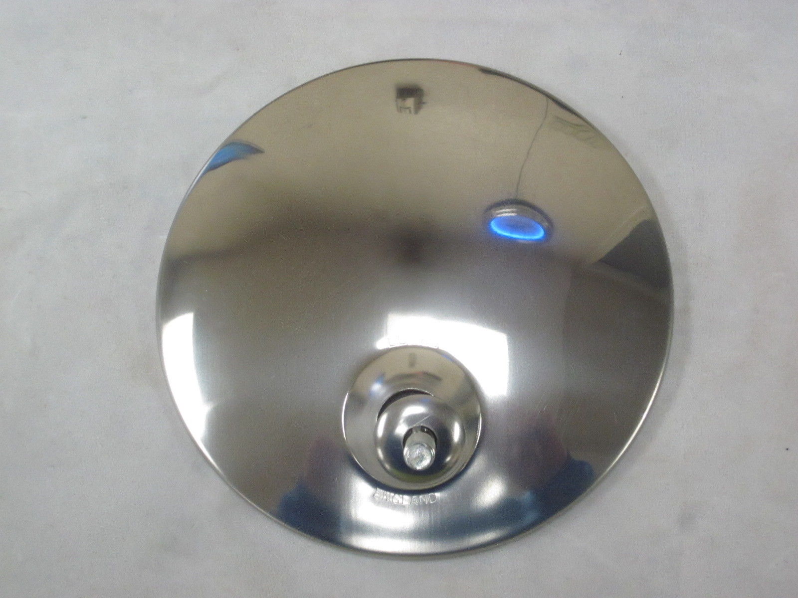
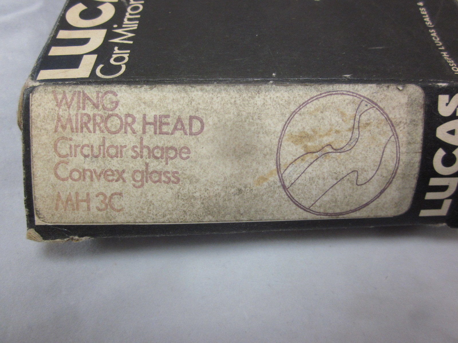
As we will see later, Magnatex had meanwhile introduced the so-called “spring back” system whereby the complete mirror was mounted on a spring mechanism allowing the assembly to flex in case someone/something hits the mirror. Lucas’ answer was to use special mounts to be placed between the existing mirror base and the wing (fender). These wing mirror “spring back” type of mounts had part number Lucas 062624. These mounts included a spring mechanism encased in rubber. The screw on the photo is only for packaging/transportation purposes.
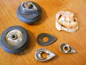 Special Lucas kit 062624 for “Spring back” upgrade

Change-over from Lucas to TEX (Magnatex)
(Magnatex Limited in 1962: Bath Road, Harlington, Hayes, Middlesex, UK.)
In the early 1960s a (gradual?) change-over took place whereby Lucas mirrors were replaced by mirrors manufactured by Magnatex under the brand name TEX. Lucas catalogue CCE 906/62 of April 1962 “Quality Equipment and Spare Parts 1962 – Jaguar” only lists an Interior Mirror (Lucas 680) and no exterior mirrors any more. However, we do know that the supply of Lucas model 406 and 407 exterior mirrors continued until the early 1970s.
This is a rather difficult period to establish which mirror version was used on what model. In the early 60s we see mirrors on the XK 150 (and the Mk VIII as well) that sometimes are Lucas while others are TEX. Of course this could also be a mix of “factory optional extras” and dealer mounted mirrors, but the information available does not provide a clear timing for the change-overs. Some input for discussion:
According the Spare Parts Catalogue the Jaguar XK 150 (and the Mk VIII) received a revised wing mirror with Jaguar part no. C16114 for both sides in the early 60s. After the introduction of the E-Type in 1961 this mirror was also an “optional extra” on this car. This mirror, manufactured by Magnatex (TEX), had a spring loaded base, curved arm, round head and a flat mirror glass. It was no longer handed but fits the LH or RH side because the mirror head can be installed from two sides. There are apparently two versions of this wing mirror: Jaguar C16114 and Jaguar C16114/1 which have the same stem (bracket) but the first has a round mirror head while the latter has a (tapered) rectangular shaped mirror head. Most Jaguar part suppliers of today provide these mirror types as part number C16114 (or C16114/1).
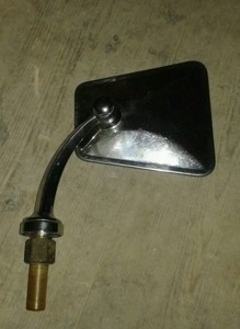 Jaguar C16114/1 with “continental” mirror head
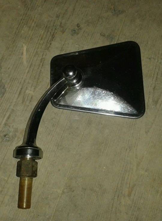
The Jaguar Mk IX (1959 – 1961) also had two C16114 Wing Mirrors available as “Optional Extras”. They were mounted on a line 1″ outside a straight line from the (red plastic) indicator in the sidelamp casing, and vertically, on a straight line up from the centers of the wheel hubs.
The use of Jaguar C16114/1, however, may have been short lived as becomes clear from Jaguar’s proposed solution in Bulletin A.13 dated December 1961. This bulletin describes a TEX “Viewmaster” adjustable mirror bracket of the “Spring Back” type with “Continental” type mirror head : this “Continental” mirror head type is (tapered) rectangular and no longer round. Also note that the mirror is placed on the bonnet (hood) of the E-Type. This TEX mirror apparently received Jaguar part number C19909. These mirrorrs were supplied with the car but not installed because of transport problems.
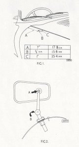
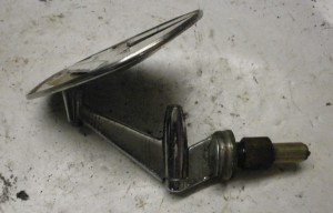 C19909 from 1968
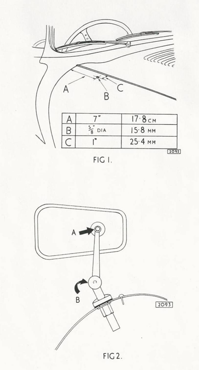
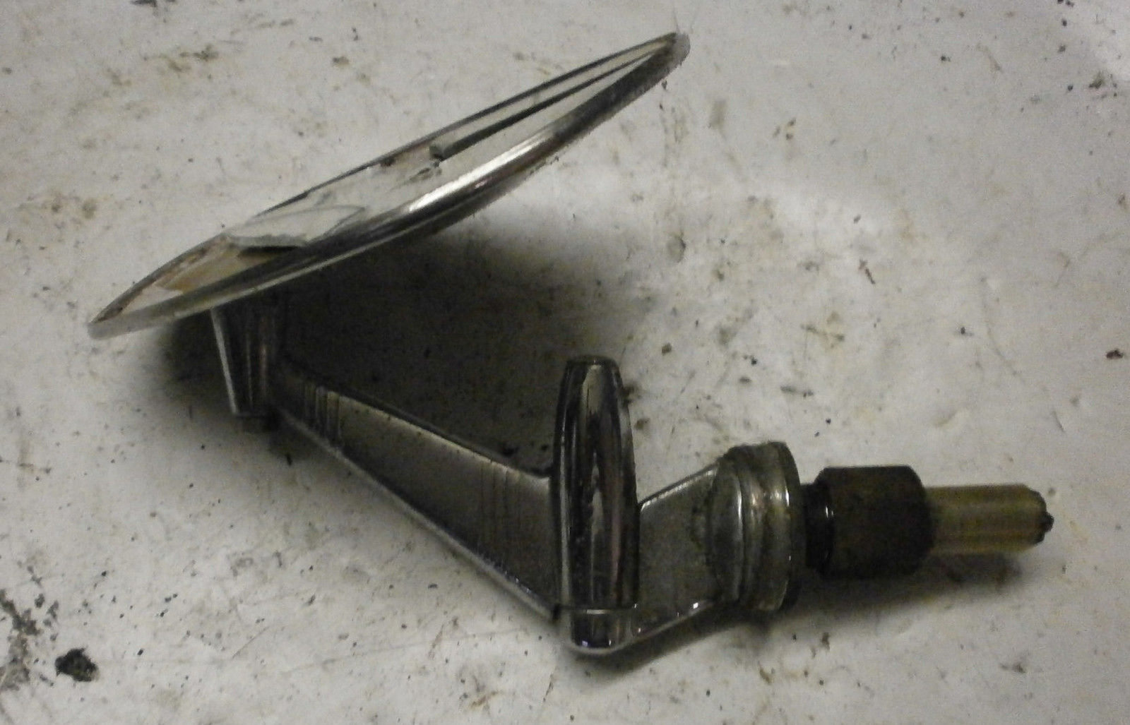
So it looks like wing mirror C16114 was replaced soon after its introduction by Jaguar part number C 19909 which is defined as Magnatex M2VC/6C. This C19909 wing (fender) mirror was fitted to cars exported to countries where external mirrors were compulsory like Belgium, Denmark, France, Germany, Holland, Luxembourg or Switzerland. It was also supplied to special order.
The same TEX system could also be supplied with a round mirror head, as can be seen on the photo below. This type of adjustable bracket has been used on Jaguars from the early till the mid 60s (e.g Jaguar S-type).
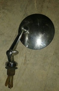 TEX adjustable bracket with round mirror head

Later Jaguar Mk10 and 420G cars had wing mirrors Jaguar part number C20819 with additional description MC120/6C which we assume is also made by TEX. This (most likely) is the last wing mirror used by Jaguar after which only door mounted mirrors were used as exterior mirrors. Jaguar Service bulletin A 15 dated July 1962 shows the correct position 14 1/2 inches back from the edge of the outboard lamp. It also shows a drawing of the correct mirror C20819.
For the year 1968 all LHD E-Types got a new LH door mounted mirror Jaguar C.28517 which is also described as SA365 (which might be a TEX number). The matching RH door mirror has Jaguar code C30827. This mirror is also known as the “Swan Neck” and can also be (or has been) used as a wing mirror. This mirror is mounted using two self-tapping screws and a hole (special shape) that allows the use of two speednuts in the door skin or wing. This mirror is still available.
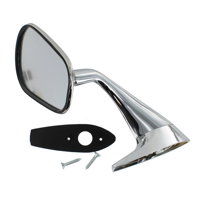
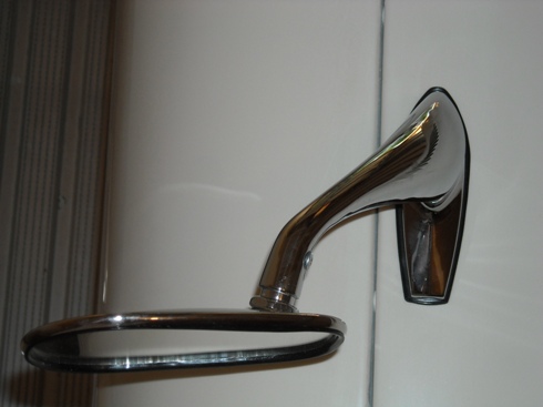
Door mounted Jaguar C28517 “Swan Neck” mirror. Also wing mounted on e.g. later E-Type (Right)
Modern replacements
The “Lucas type” wing mirror is newly available from most parts suppliers, but in many cases these are not entirely identical to the original version (either generation 1 or 2):
- The Clamp part number 620786 is often not stamped “Lucas Made in England”.
- The casted (part) numbers at the underside of the Brackets have been deleted.
- The 3 screws for the clamp should be of the “raised countersunk” type with a slot, whereas the modern versions have “pan head” crosshead screws.
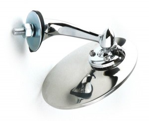 Modern replica “Lucas style”

However, based on the data provided in this survey, it should be possible to find a contemporary (derived) version that still has the required correct parts.
For the more specific types (example “third generation”) it will be much more difficult, but they are offered from time to time on e.g. Ebay.
TEX mirrors are still manufactured today, although not always completely identical to the specific version you might be looking for.
Trico illuminated (overdrive) switch
Trico illuminated switches
Besides the well-known vacuum equipment for wipers and washers, Trico also manufactured a large variety of switches as part of their programme for the automotive industry. One of the most “famous” versions is the PS (Pilot light Switch) range with an illuminated, transparent handle. This is a specific UK developed and manufactured product.
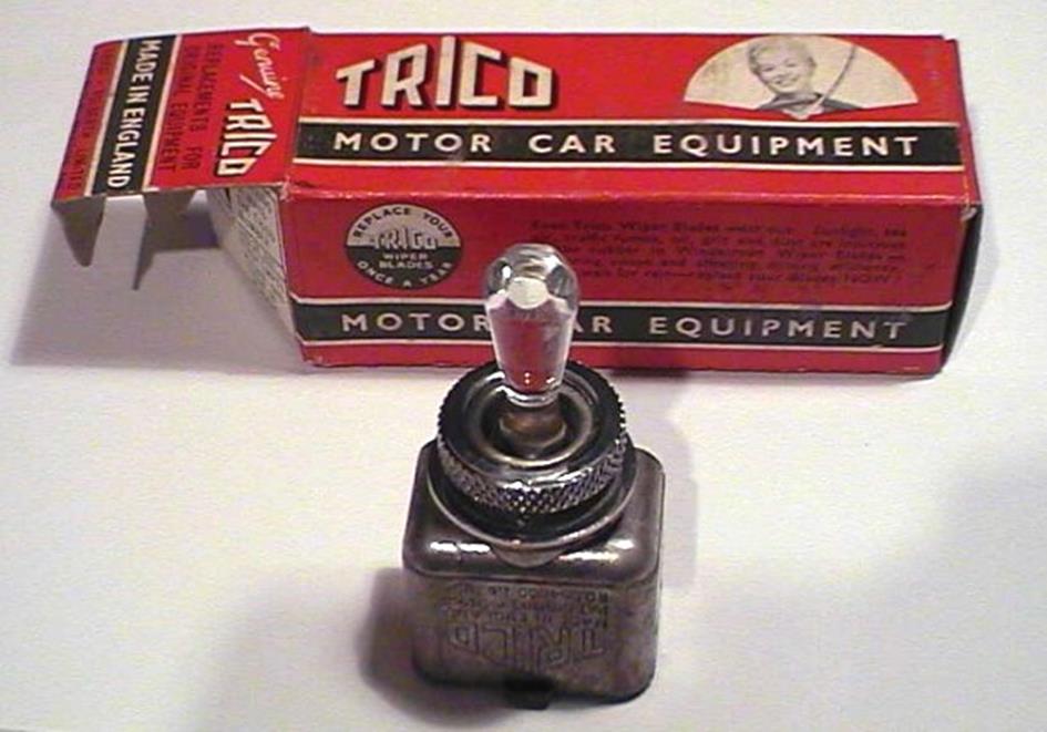
Switches have been supplied during the 1950s and 1960s after which production in the UK ceased.
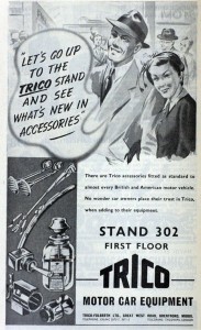 1951 advertisement with Trico PS type of switch
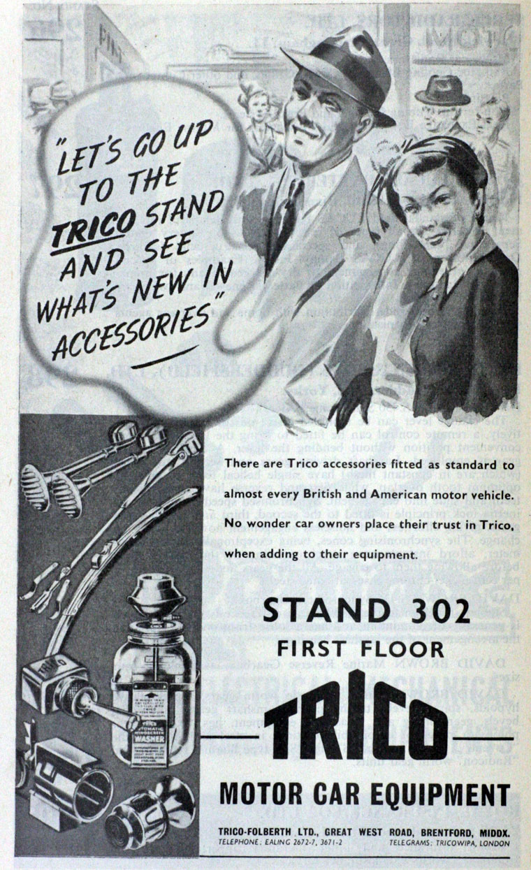
The Trico PS (Pilot light Switch) range.
The range consisted of at least 7 versions (but possibly more), each one intended for a specific application like:
- 2 or 3 positions (1 way or 2 way switch)
- specific load to be switched
- which signalling function required
- required bulb colour
- 6 Volt or 12 Volt execution
The switch is to be mounted in a panel using a ⅝” or 16 mm hole. A chromed knurled ring, acting as nut, secures the switch to the panel.
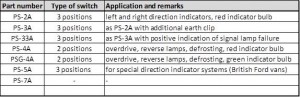 Survey of PS switches
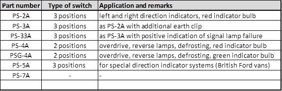
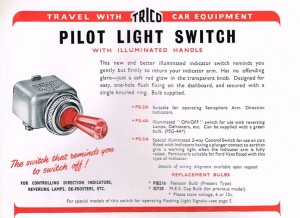 Catalogue 1953 (courtesy Roger Payne)
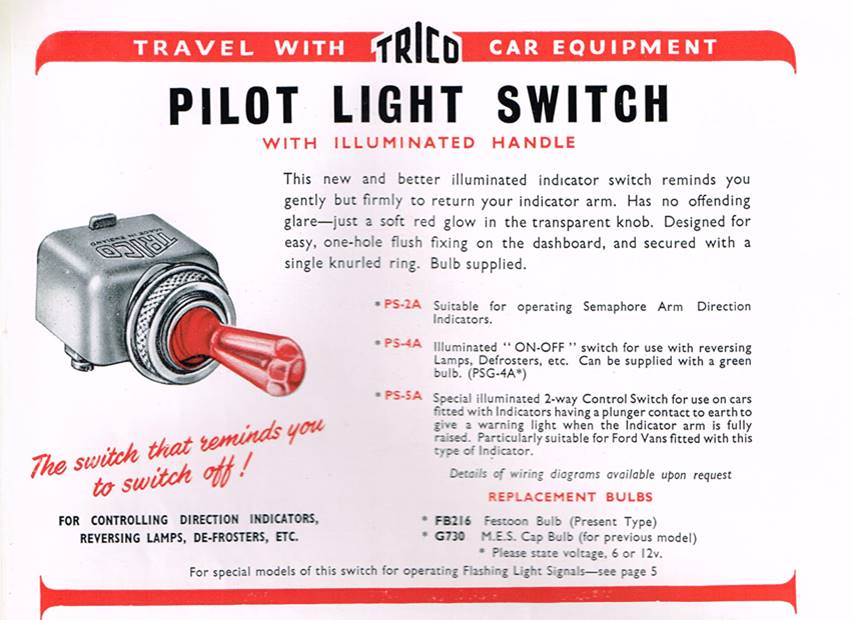
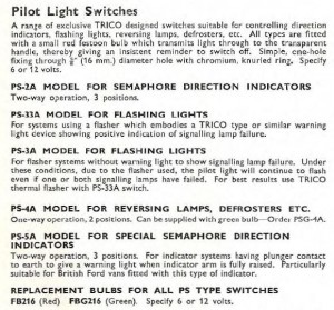
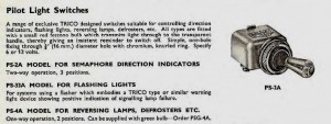 Catalogue 1959 Catalogue 1960
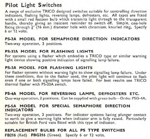
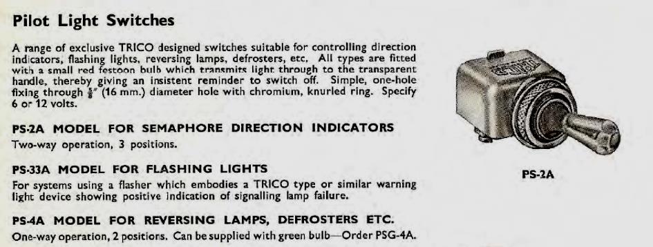
The PS switch construction
All switches used the same aluminium die cast housing, suitable for 3 positions. The signal lamp was positioned on a (thermoset) plastic cover at the bottom of the switch, whereby the number and position of contacts depended on the signalling function.
In case of a 2 position switch a rubber buffer was placed at one side within the aluminium housing blocking the 3rd position.
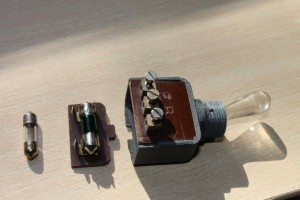 Typical construction
Jaguar application of the PSG-4A switch
Although Lucas recommended their manual overdrive switch type 9RW (Lucas part number 31587 or 031648) in combination with Laycock overdrives, Jaguar instead opted for a Trico switch in spite of the very close relation with their “preferred supplier”.
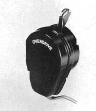
Lucas overdrive switch 9RW used on Armstrong Siddeley and Triumph
In 1954 Jaguar introduced the PSG-4A as an overdrive switch on the XK140 (and other contemporary models like the Jaguar Mk VIIM and Jaguar Mk1) with Jaguar part number C7474. This switch had 3 screw terminals of which two were marked: the middle had the letter B (battery) and the other with the letter E (earthing the signal bulb). The third (unmarked) contact is connected to the Overdrive Relay(s). This switch originally had a green “festoon” bulb (although many may have received a white replacement bulb in the past decades). The replacement Trico bulb FBG216 received Jaguar part number C8829.
Note that the PS-4A version is normally supplied with a red bulb, but Jaguar opted for the green bulb.
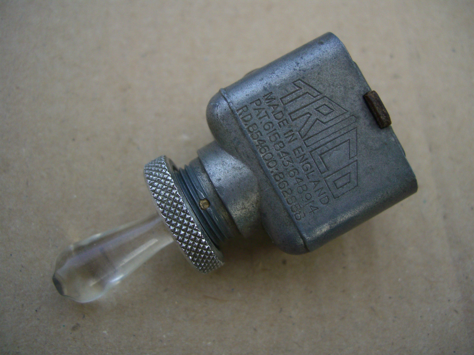
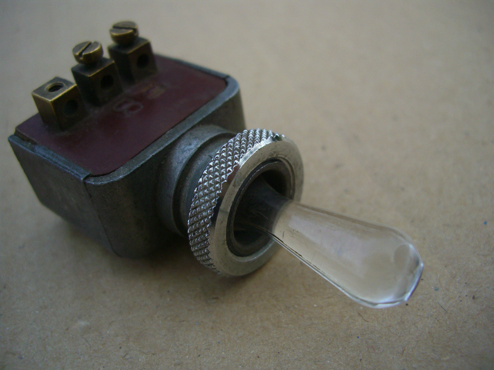
Note: For the XK150 Jaguar changed over to part number C12832 (81053 JSB) which is not further discussed here. Also the Mk2 used a different (Lucas) switch type 52SA with Jaguar part number C15611 (Lucas part number 31965A) followed by SA52 type switch with part number C23391 (Lucas 34804).
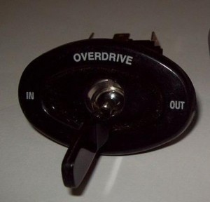
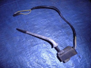
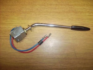 C12832 C15611 C23391
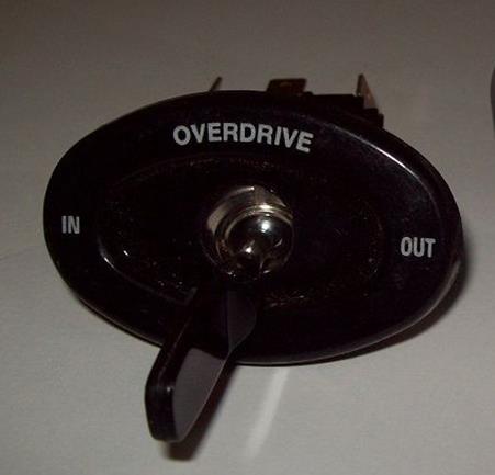
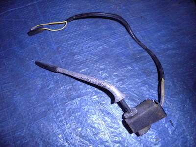

Examples of other Trico PS switches
The PS-33A is used as a direction indicator switch. It has additional screw terminals for the festoon bulb at the bottom of the switch. It is not a direct replacement for the Overdrive switch PSG-4A.
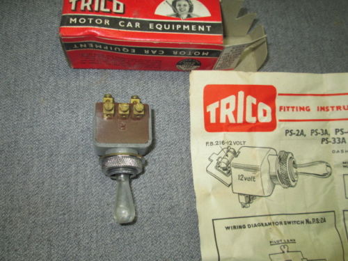

 Complete box with 6 pcs Trico PS-33A
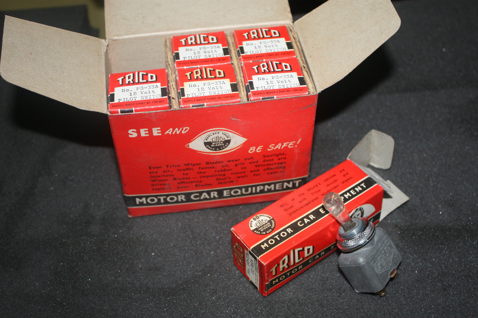
Trico “Festoon” bulbs
The bulb was of the “festoon” type and was supplied by Trico. There are 2 known bulb colours: red and green. The Trico part number for the built-in indicator bulb is FB216, which is a 12V 1.5W festoon green bulb of 22 mm length. Trico provided a large range of “festoon” bulbs: only the FB216 version was correct for the PS switches.
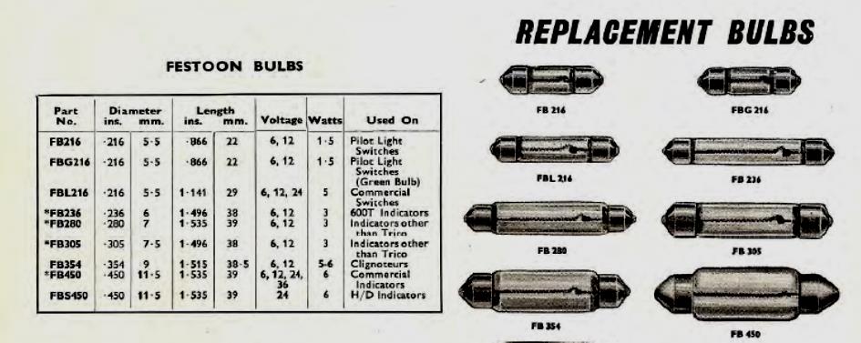
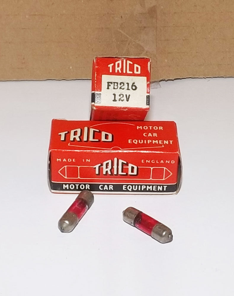
Green replacement bulbs are very hard to find. In Germany a similar bulb type is coded S6 (6 x 24 mm) 12 volt available in either 1.2 W or 2.0 W with S5.5 bulb contacts. The standard diameter of the original Trico bulb is 0.216” or 5.5 mm so the S6 version will fit. Sometimes available in green but 2W instead of 1.5 W (e.g. Scharnberger 25929).
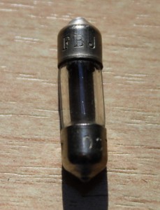 Replacement bulb FBJ 216 (S6 6 x 24 mm 12V 2 W)

Lucas Le Mans 24 headlamps on XK’s
Introduction
Although the export share of British sports cars going to the USA was much bigger than those heading for continental Europe, Lucas acknowledged in the early 50’s the necessity to come with an improved, highly efficient light unit for (fast) driving on the (European) continent. Lucas opted for “vertical dipping” making use of British Pre Focus (BPF) bulbs.
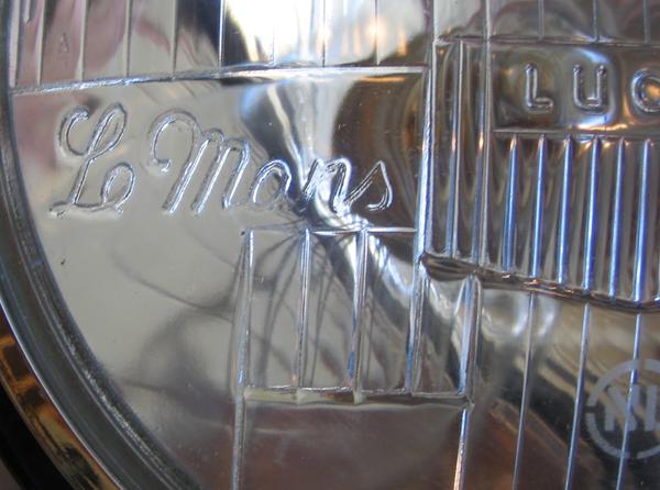
Given the formidable British racing successes in Le Mans, the PR department of Lucas decided that this headlamp series would be called “Le Mans 24”. Although some sources indicate that these head lamps had been specially developed by Lucas for racing at Le Mans, this is factually incorrect. The assignment for the Lucas development group was much more complicated because Lucas management wanted a very efficient head lamp system that could fulfil the legal requirements for road use in different (continental) European countries and that could be formally approved for those countries. Remember this was far before any form of European cooperation and legal requirements differed per country, often based on national laws that had been developed per country in “splendid isolation”.
The legal requirements for headlamps in the USA were totally different (and partially still are today): the “Le Mans 24” lamp was never intended to become an alternative for the USA. We will not enter here into a formal comparison of the legal requirements for the various continents and countries. We will however emphasis the requirements in some European countries that later formally approved the “Le Mans 24” headlamps, often in combination with the initial type approval of a car for that particular country.
 Lucas “Le Mans 24” for XK 140

Jaguar was a technological forerunner in general and the first company to introduce the “Lucas Le Mans 24” on a production car, destined for Continental Europe: the Jaguar Mk VII carried the Le Mans 24 headlamp unit with Lucas type number 51472A and 51478A from 1952 onwards.
Vertical dipping
Traditionally European manufacturers created a main and dipped beam from a single bulb by introducing two filaments along the axis of the (parabolic) reflector. The high beam filament is always in the focal point of the reflector whereas the dipped beam filament is somewhat “out of focus”: in most cases about 10 mm to the front and 3 mm above the axis. European (continental, thus excluding Great Britain) legal requirements include a sharp cut-off beam pattern which is normally secured by a (cup-shaped) shield below the dipped beam filament which prevents that light would be reflected above the horizon. The bulb has a fixed position in the headlamp securing that the shield is always in the correct place below the filament. There are also other versions than vertical dipping available like RH and LH dipping, but they will not be discussed here.
Also note that in 1956 most continental European countries (again excluding GB) agreed to a new beam pattern in which the beam at the RH (or “passenger side”) of the light unit has been lifted 15 degrees: the typical arrangement that later became the EU standard and basically is still valid today. The Lucas “Le Mans 24” light unit does not fulfil this 1956 standard as its beam pattern has a (very sharp) cut-off over the entire width of the beam. Fortunately in most EU countries the legal requirements have been made in such a way that headlamp requirements contain a mandatory element for the sharp cut-off aspects, with the later (1956) addition that if there is a 15 degree lifted part in the beam, this has to fulfil a number of specific requirements. This implies that in most EU countries that had the sharp cut-off dipped beam pattern standardized before 1956, the “Le Mans 24” light unit would/should be accepted when offered for initial type approval or periodical testing.
Different types of Le Mans 24 light units
The most common version of the Le Mans 24 light unit is Lucas part number 554665 for use with BPF bulbs with lamp base P22d36.

Lucas BPF bulb 350 and 370 with base P22d36 French 3 pin bulb with base BA21d branded Marchall
France was a completely different case with their legal requirement of April 1937 to have yellow headlights in combination with a 3 pin lamp with base BA21d. This was a 36/45W bulb with a 40 mm globe-shaped yellow glass envelope. This bulb type was not manufactured by Lucas (nor by their UK bulb suppliers). Instead Lucas offered an adaptor/bulb holder Lucas part number 562303 to accept BA21d bulbs.
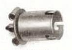
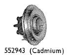
Lucas bulb holder for BA21d Lucas “Shell Adaptor” with bulbholder positioned
From about 1954 Lucas offered a 3 pin BA21d version of the “Le Mans 24” light unit intended for France. The first introduced version was a light unit with Lucas part number 554615. This has not been used by Jaguar (but Aston Martin and Bristol did use this version for Export to France in 1954). This first light unit was succeeded by a second version Lucas part number 555288 which was used by Jaguar for Export to France.
Both the 554615 and 555288 light unit have a larger opening at the back of the reflector (over 40 mm in diameter because of the 40 mm globe-shaped glass of the French bulb) whereas the BPF has an opening of about 22 mm. This French system uses a “Shell adaptor” (Lucas 552943) which is a ring to close the gap between the larger reflector opening and the smaller outer diameter of Lucas bulb holder 562303. The Shell adaptor 552943 was delivered complete with Bulb holder 562303 (as in the above picture).
 Lucas PF700EF light unit; part number 554288
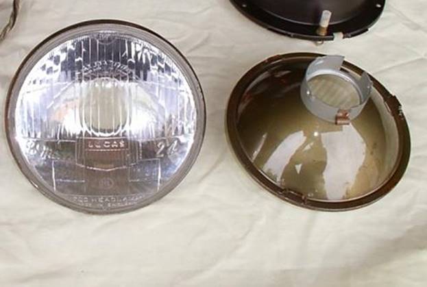
The French Bulb holder and Shell adaptor combination also had to compensate the lamp centre length difference of the BPF and the 3 pin BA21d bulbs (LCL: distance from centre of filament to bulb base).
Survey of “Le Mans 24” light units
So resuming we have three different light units, all branded “Le Mans 24”:
- Lucas part number 554615 using 3 pin BA21d bulb for France
This is a special reflector unit with a different mounting of the bulb (adaptor) using two clips (in stead of the bajonet fitting of the other Le mans 24 reflector units). The front glass had a special mark reading “Agréée AB-TP No 457” placed in a dashed rectangle. This is a French homologation mark for approved headlights fulfilling the French requirements as laid down in 1930. The bulb was not provided by Lucas but had to be placed by the Jaguar agent in France (see hereafter).

Back of light unit 254615 Lucas Le Mans 24 unit for France with homologation mark
- Lucas part number 554665 using BPF bulb for Europe (excl. GB and France)
This unit is closely related to the PF700 versions for the British Pre Focus bulbs and also used the same bulb holder, basically Lucas Bulb holder 556402 with suitable wiring (as assembly: Lucas 858543).
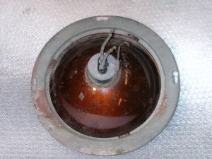 Back of “Le Mans 24” reflector Lucas 554665

- Lucas part number 555288 using 3 pin BA21d bulb for France
This light unit is related to the Lucas J-700 unit (with different lens of course), using the same bulb holder Lucas 554855 and Shell adaptor 554909.
Back of “Le Mans 24” reflector Lucas 555288
All these light units share the same glass front lens with part number Lucas 554 359 moulded in the glass in a vertical direction just to the right the centre prisms.
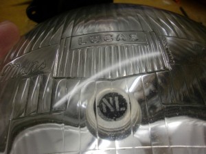 Part number for front lens moulded in glass
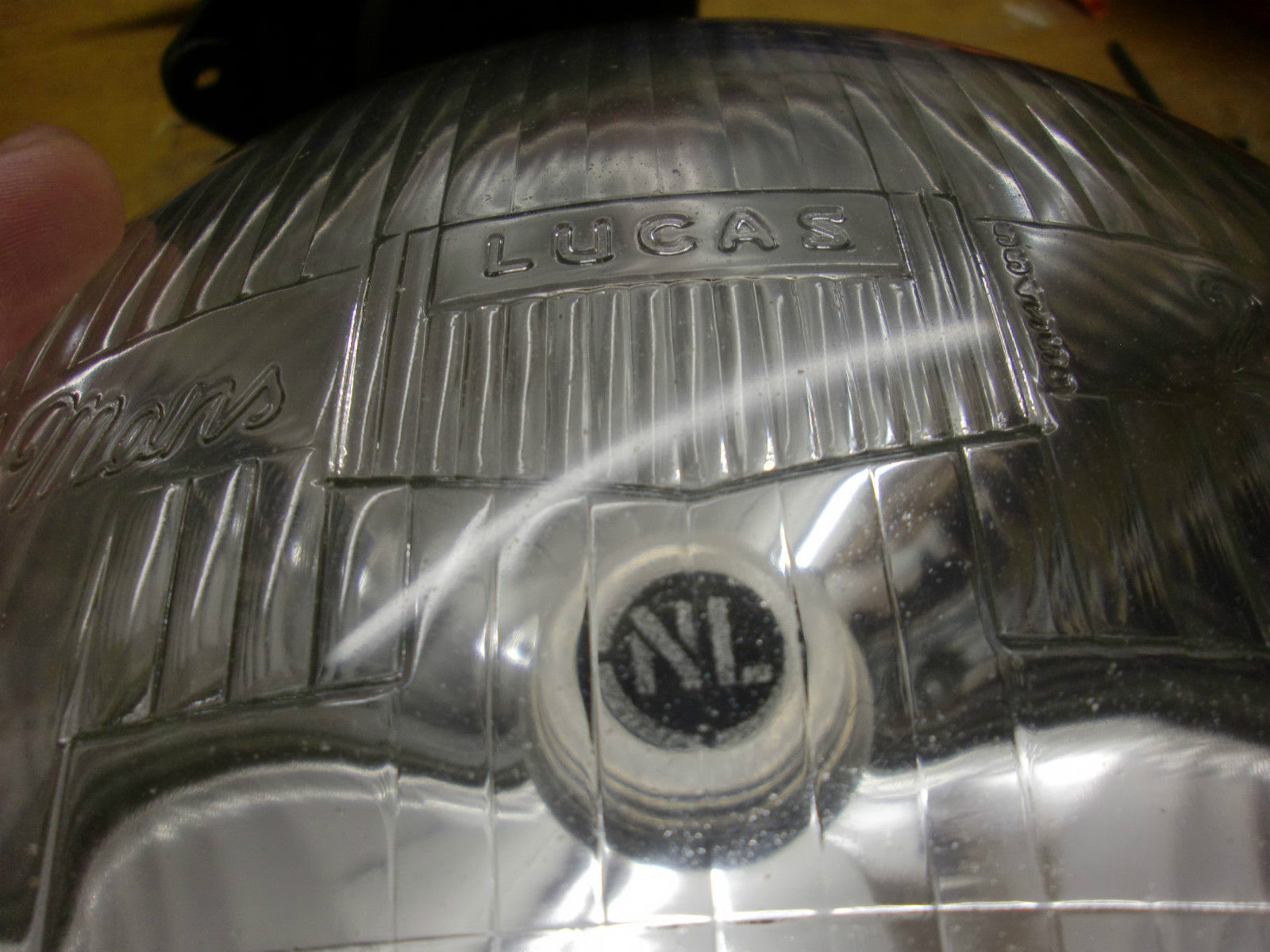
Manufacturing over the years
Initial production started probably somewhere in 1953 and continued until mid 1960’s. Light units from the initial production can be recognized by the fact that the factory identification is shown in the form of the letters M5 at the bottom of the lens and the NL mark in a circle etched just below the centre. The factory indication (M5) was followed by a date code consisting of one or two letters. I’ve found the following codes on my Le Mans 24 light units: M5 X, M5 AA, M5 CD. Other sources also indicate M5 XX as a date code.
 Original 50’s and 60’s production

Lucas remanufactured the “Le Mans 24” headlamps around 1976, however without the text “700 HEADLAMP”, the factory indication (M5) and the NL mark. We will later see why the NL mark was no longer required.
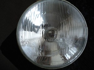 Later (1976) Lucas production
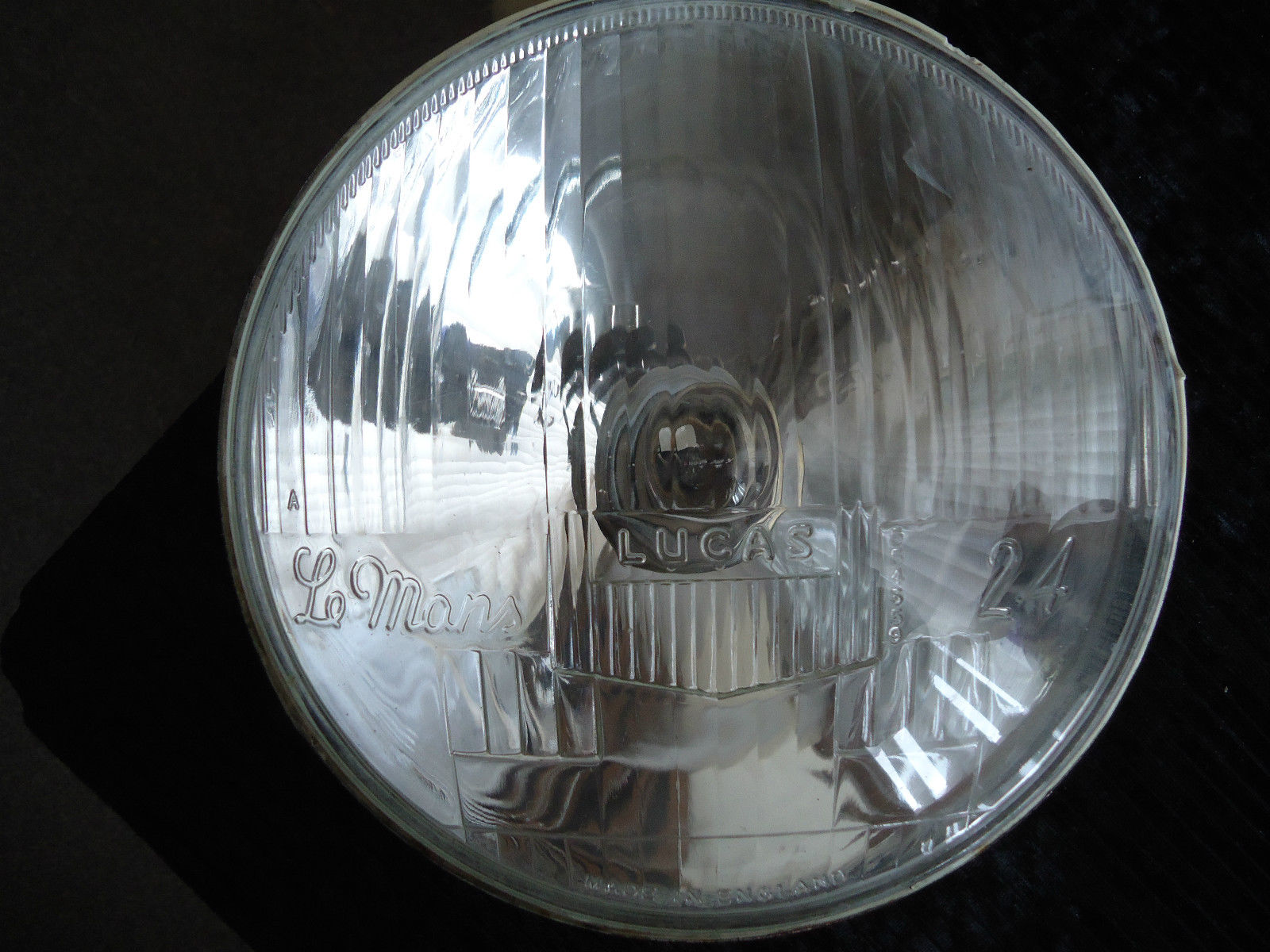
Some small companies have made replicas in more recent years, like the excellent versions manufactured by VHR (Peter Appleyard) of Sheffield (UK).
Since a couple of years replicas have been produced in larger quantities and of a somewhat lower quality: the “Le Mans” and “Lucas” lettering as well as the font of the part number of the front lens is not an exact copy of the original. In addition the “NL” mark is no longer etched but moulded (raised) in the glass which makes it very easy to recognise a reproduction lamp. In addition they tend to form a thin white layer on the inside of the glass lens due to vaporization of the kit used during manufacturing, which apparently has not sufficiently cured (a well known problem in headlamp manufacturing). Prices are rather attractive compared to originals.
 Modern replica

More importantly, the beam patterns of these modern replicas are not of the quality of the original Lucas beam patterns as can be seen in the pictures below. The picture on the left shows a well defined beam with a good horizontal cut-off line, the result of using the original Lucas Le Mans 24 headlamp and a good quality bulb. The pitcure on the left is an example of the beam pattern of a Repro Le Mans 24 headlamp using a good bulb. The pattern is rather “undefined” and the horizontal cut-off is far from perfect.
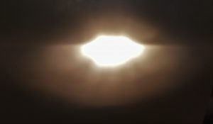
 Original Lucas Le Mans 24 beam pattern Reproduction Le Mans 24 beam pattern

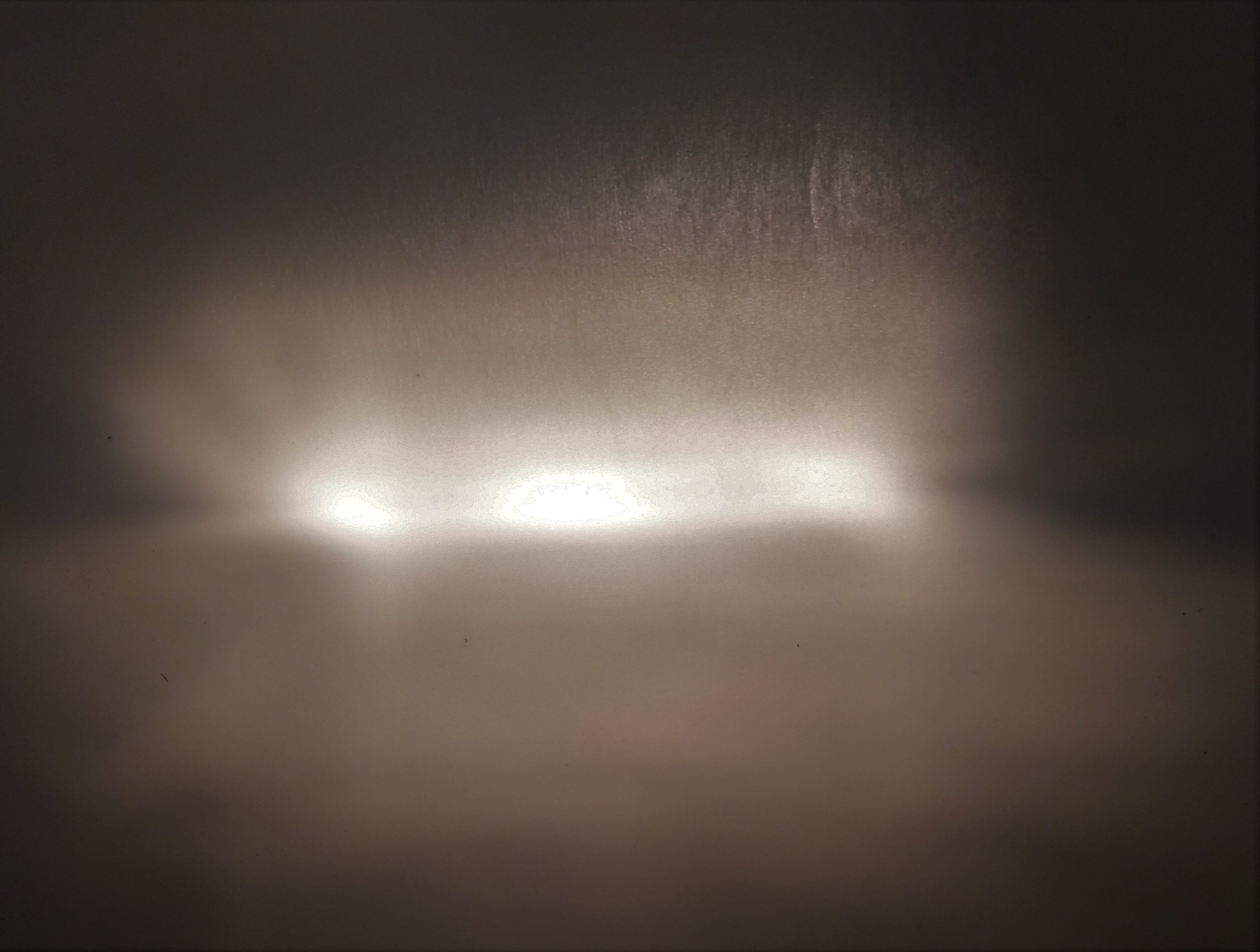
Survey of Jaguars using “Le Mans 24” headlights
Many jaguars in the period 1953 to 1960 destined for a number of continental European countries had the “Le Mans 24” headlamp although the actual types differ somewhat per car. The survey below shows the “Le Mans 24” types used for the XK types as well.
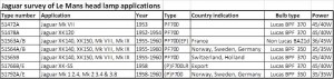 Click to open table

We mentioned already that there was no standardization of vehicle lighting (yet) in Europe. This is also the reason why different bulb types are used for different countries on the continent, also driven by the (interest of) national lighting industries like Osram (Germany), Philips (Holland) and Mazda, Philips and Marchal (all in France), not forgetting the British lamp industry in their attempt to keep the BPF bulb alive.
Norway, Sweden and Germany had national requirements stating that the maximum power (per filament) of the bulb should not exceed 35 Watt. This is the reason why the “Le Mans 24” versions destined for these three countries used Lucas bulb 350 (other reference: Philips 12721).
Switzerland and Holland (or better The Netherlands) allowed a two-filament bulb with 45 and 40 Watt power, meaning for these countries Lucas bulb 370 (other reference: Philips 12741) was used.
As mentioned before, France was a completely different case with their 1937 legal requirement to have yellow headlights in combination with a 3 pin BA21d 36/45W yellow bulb (reference Philips 12736 Y). Lucas provided dedicated “Le Mans 24” light units for this, initially coded 554615 and later 555288.
XK 120 with “Le Mans 24” headlamps
Note: XK 120’s normally had the PF770 headlamps whereas the Le Mans 24 headlamp belongs to the PF700 group. The Le Mans 24 headlamps had the same outer chrome rim although the light unit was of course smaller. This was solved by using a different “light unit retaining plate”. See the complete survey under chapter “Le Mans 24” Headlight fixation systems and parts.
XK 120 (1952/1954) for Norway, Sweden and Germany
Not specified by Jaguar for the XK 120, but following the information provided in various Lucas catalogues these cars may (could) have been executed from 1952 onwards with Lucas 51478A (Jaguar part number unknown) using the “Le Mans 24” light unit 554665 whereby the standard bulb Lucas 370 has been replaced by bulb Lucas 350 which is a BPF P22d36 lamp with 35W/35W filaments.
XK 120 (1952-1954) for Switzerland and Holland
According the Lucas 400D & E catalogue (but not mentioned in the Jaguar SPC) these cars had the same Lucas 51478A unit (Jaguar part number unknown) installed, using the Le Mans 24 light unit 554665 in combination with bulb Lucas 370 which is a BPF P22d/36 lamp with 45W/40W filaments.
Late XK 120 (1953-1954) for France: no “Le Mans 24” units
The Lucas “Le Mans 24” light unit was not yet available for the French market. Modified PF770 versions were still used for France with initially Lucas part number 50840/A and later 50780/A; both used Lucas light unit 553961. Also reference is made of Lucas 51194B which was a later replacement version for all “French” version for the XK 120 1949-1954, however with a different light unit (Lucas 553948).
XK 140 with “Le Mans 24” headlamps
XK 140 for Norway, Sweden and Germany
These cars had Lucas 51564A/B (Jaguar part number C5626) installed, using the “Le Mans 24” light unit 554665 in combination with bulb Lucas 350 which is a BPF P22d36 lamp with 35W/35W filaments.
XK 140 for Switzerland and Holland
These cars had Lucas 51565A/B (Jaguar part number C5625) installed, using the “Le Mans 24” light unit 554665 in combination with bulb Lucas 370 which is a BPF P22d36 lamp with 45W/40W filaments.
XK 140 for France
Special version for France only with Lucas 51563A/B (Jaguar part number C5627) installed, using the “Le Mans 24” light unit 555288 and no bulb was provided by Lucas. Lucas provided bulb adaptor 562303 (intended for the BA21d 3 pin base) in combination with Shell adaptor 554909 with the head lamp unit. It is assumed that the French Jaguar importer Delecroix (or even a local Jaguar dealer) installed a 3 pin yellow 36/45W filament bulb. We assume that this bulb was manufactured by various French bulb manufacturers (like e.g. Norma, Mazda and Philips) and was branded Marchall with code Granilux 12V 36 / 45 W and approval number Agréée ABTP 288.
XK 150 with “Le Mans 24” headlamps
XK 150 for Norway, Sweden and Germany
These cars continued the use of Lucas 51564A/B (see XK 140).
XK 150 for Switzerland and Holland
These cars continued the use of Lucas 51565A/B (see XK 140). Note: this headlamp is now indicated by Jaguar as F700 whereas the same item is indicated as PF700 for the XK 150 for Norway, Sweden and Germany; it may be assumed that this is an omission as also the Lucas catalogue still uses the PF700 description.
XK 150 for France
These cars continued the use of Lucas 51563A/B (see XK 140). Note: the french headlamp for the XK 150 is now indicated as F700EF, whereas the same item is indicated as PF700EF for the XK 140; it may be assumed that this is an omission as also the Lucas catalogue still uses PF700. Also to be noted that Lucas used the code EF for their entire product portfolio as an abbreviation for “Export France”.
XK-SS with Le Mans 24 headlamps
The XK-SS destined for the USA in 1958 received the Lucas “Le Mans 24” light unit but in this case without the typical large chrome rims as used on the XK’s. This headlamp was of the (P)F700LR (Long Range) type with code number 51766B/E which assembly made use of the 554665 light unit and the 370 (45/40W) bulb. This description in fact refers to the “Switzerland and Holland” specification; versions for Norway, Sweden and Germany could be obtained by changing the bulb for the Lucas 350 type. No indication exist for a possible Export France version.
“Le Mans 24” headlight fixation systems and parts
To understand the evolution of the “Le Mans 24” fixation over the different generations of Jaguars, we have to know the way the older PF770 headlamp systems were mounted.
PF770 Headlamp fixation till March/April 1950
The fixation of early PF770 headlamps (with the “inward flange” headlamp bowls/domes/ buckets) was different from all later versions. The horizontal beam adjustment was done with a LH and RH bracket attached to the Fixation ring and two screws fixed to the Retainer rim. The screws were placed in a radial direction (see pictures below). The vertical adjustment screw (at the top of the light unit) was placed in the direction of the lamp axis (like all later adjustment systems. The fixing ring had a riveted tapped plate for the screw and a short compression spring.
 Early PF770 system


This system (on basis of the headlamp bowl/dome/bucket with the inward flange; see photo below), used the following parts (for the XK 120):
- Fixation ring Jaguar 3450 or Lucas 552704, complete with two brackets for horizontal adjustment of light unit
- Retaining rim Jaguar 3430 or Lucas 552686, no ears for fixation but a wire spring was used instead; two tapped holes for the (horizontal) adjustment screw
- Wire spring Jaguar 3441 or Lucas 552687


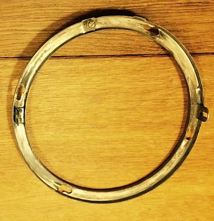
Note that the headlamps for 7 inch USA & Canada Sealed Beam light units had a different Fixation/Retaining ring Jaguar 3450 (Lucas 553614) with a different inner diameter to match the smaller light unit size.
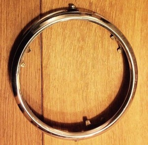 Lucas 554596 Retaining Ring Sealed Beam unit (early/late PF770)
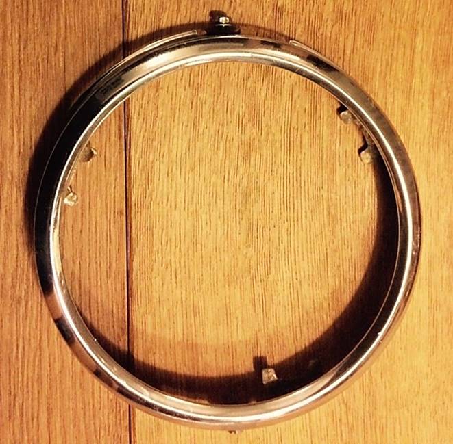
PF770 Headlamp fixation from March/April 1950 onwards
The headlamp bowl/dome/bucket had now changed to Lucas PF770 Mk II with an outward flange, which also changed the fixation method of the light unit itself: screws were used now instead of the wire spring:
- Fixation ring Lucas 553877; zinc plated
- Retaining rim Lucas 553878 with 7¼” aperture; fixation with 4 “ears” and screws

 PF770 Mk II
 Fixation ring 553877 and Retaining rim 553878
“Le Mans 24” headlamps on Jaguar Mk VII from 1953 onwards
The Lucas parts catalogue refers to the following parts for “Le Mans 24” light units first installed on a Jaguar Mk VII in 1953. None of these (post 1950) PF770 parts have been continued on the later “Le Mans 24” applications. The Jaguar Mk VII with “Le Mans 24” headlights was the first to change over to the 3 screw adjuster system.
- Fixation ring Lucas 553972; zinc plated, looking identical to to the original (later) PF770 ring Lucas 553877 but modified to accept a 7” light unit. The adjustment screw has a longer compression spring in a spot welded socket which is tapped at the bottom for the screw.
- Retainer rim Lucas 553971; chromed, now suitable for 7” light units, with a 6⅝” aperture; otherwise identical to the original PF770 Mk II rim Lucas 553878 with 4 “ears” and screws
Note that the Jaguar Mk VII by 1953 had already the (late)r PF770 Mk II headlamp bowl/dome/bucket with the outward flange, requiring a different fixation ring than the pre March/April 1950 types; installing “Le Mans 24” headlamps on earlier Mk VII versions may therefore not be feasible.

 Fixation ring 553972 and Retaining rim 553971


“Le Mans 24” headlamps on Jaguar XK 120 from 1953 onwards
Jaguar XK 120 versions (1953 onwards) equipped with “Le Mans 24” light units (Lucas 554665) used a mix of existing and new different parts. The XK 120 with “Le Mans 24” headlamps continued the old horizontal headlamp adjustment system.
- Fixation Ring (Jaguar 3450; Lucas 553614; zinc plated); this ring is also used for the USA & Canada 7” sealed beam headlamps and has two “ears” for horizontal bean adjustment and also acting as pivot for vertical adjustment (with two screws positioned horizontal) .
- Retainer Rim (Lucas 554596; chromed); probably a modified version (with a 6⅝” aperture) of the standard (later) XK 120 Retainer rim Lucas 553878 (with 7¼” aperture).
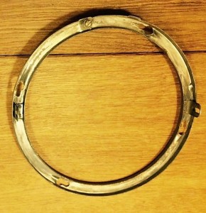
 Fixation ring 553614 and Retaining rim 554596

“Le Mans 24” headlamps on Jaguar XK 140 and 150
The XK 140 and 150 continued the use of the Lucas back shell/dome/bucket PF770 Mk II version. Remember that this is intended for 7.7” headlamps, whereas the Lucas “Le Mans 24” is a 7” light unit. With the introduction of the XK140 & 150 Jaguar changed over to the J700 concept: a 7” light unit. But also the USA and Canada versions (Lucas 51562) had a 7” light unit (although of the Sealed Beam type). The “Le Mans 24” light units (Lucas 554665) shared the same parts with the J700 and the 7” Sealed Beam versions. So XK 140s and 150s from the USA can receive “Le Mans 24” headlights, which is an advantage when these cars are brought to Norway, Sweden, Germany, Holland and Switzerland. Unfortunately the “Le mans 24” light unit is not allowed in the USA itself.
- Fixation Ring Jaguar 5302 and Lucas 554906 (zinc plated)
- Retainer Rim Jaguar 5301 and Lucas 554907 (chromed); 4 “ears” for fixation.

 Fixation ring 554906 Retaining rim 554907


“Le Mans 24” headlamps on Jaguar XK-SS (USA only)
This headlamp was of the (P)F700LR (Long Range) type with code number Lucas 51766B/E. It consisted of the following fixation parts:
- Fixation Ring Lucas 554672 ; zinc plated with 6 slots (instead of normally 3)
- Retainer Rim Lucas 554893 ; chromed. Also used for other F700 applications.

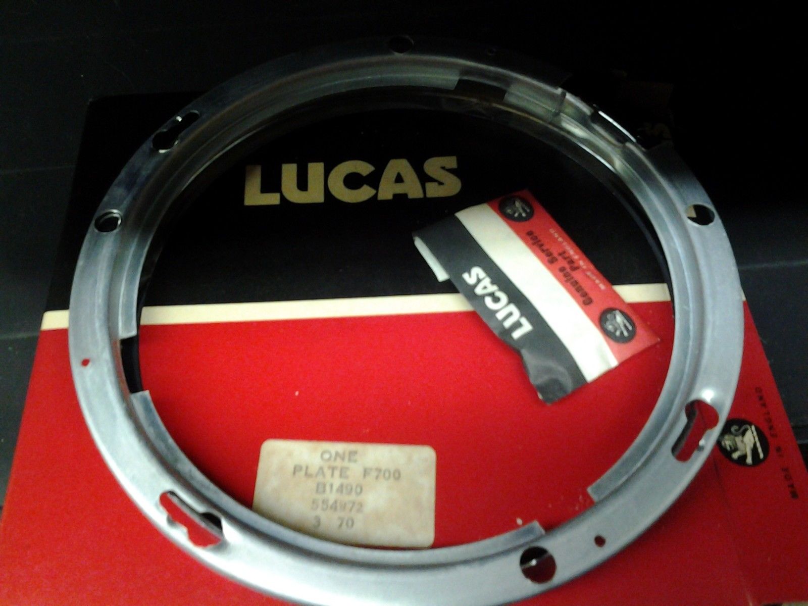
“Le Mans 24” headlamps on Jaguar Mk1 and Mk2
For addiional information the Jaguar Mk1 and Mk2 applications of the “Le Mans 24” are also presented here. In general we observe that Jaguar had definitely closed the PF770 (Mk II) era and now adopted the Lucas F700 range of components for their headlights.
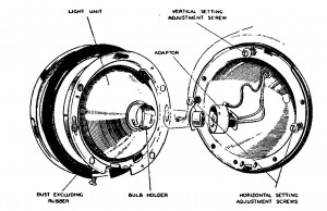 Typical (P)F700 arrangement om Mk1 & Mk2

These parts have been widely used on many British cars of the 60s: Austin, MG (Midget and B), Rover, Triumph, Morris, Mini and Austin-Healey. Spare parts should be easy to obtain.
- Fixation Ring Lucas 554782 (zinc plated)
- Retainer Rim Lucas 554781 (chromed); 3 “ears” for fixation.
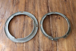
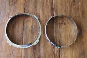 Note difference in size between XK140/150 rings (left on both photos) and Mk1/Mk2 versions
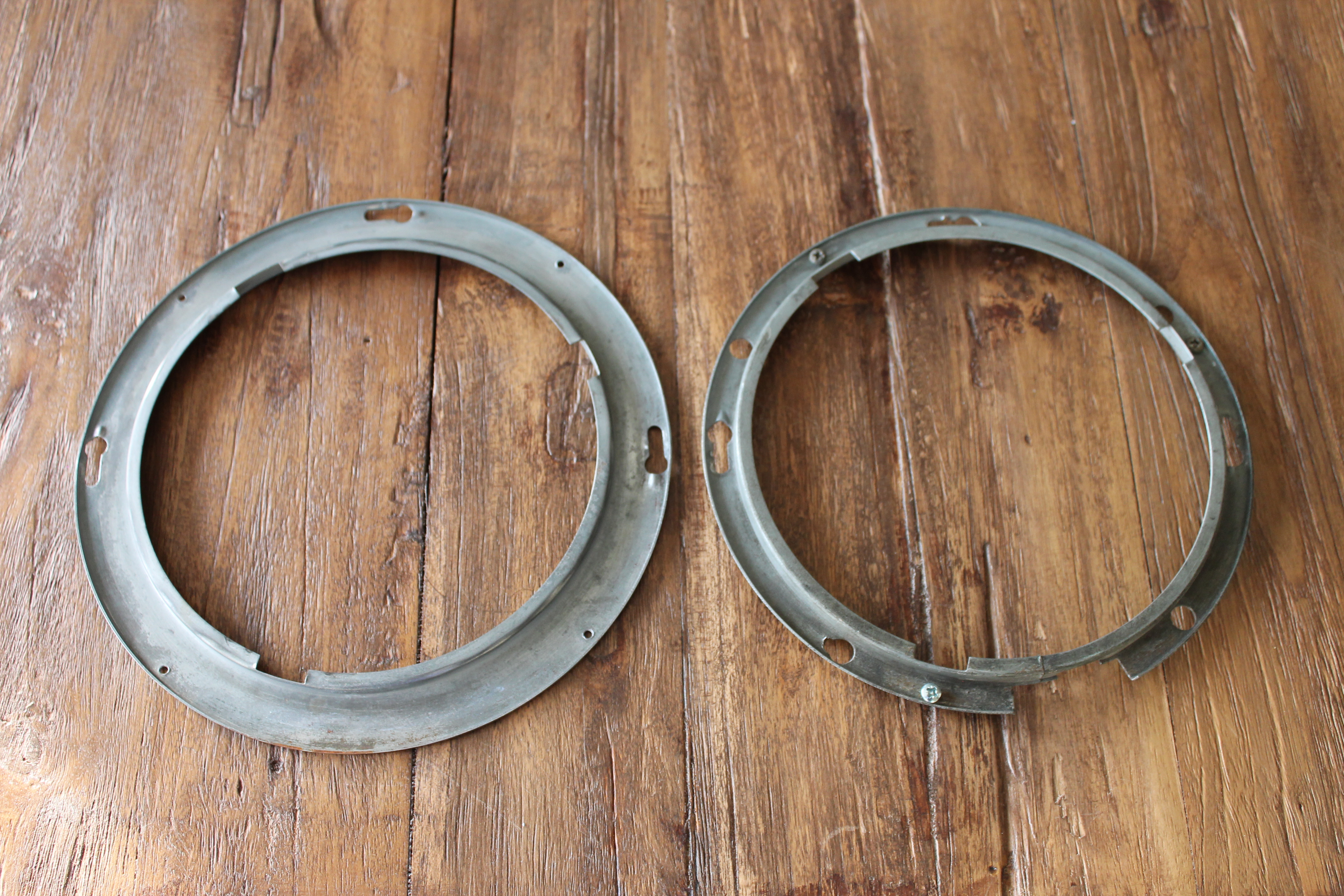

Approval marks for (continental) Europe or “The myth of the NL mark”
As mentioned above, various European countries (except GB) required a headlamp that fulfilled all legal requirements regarding the “sharp cut-off” of the dipped beam in combination with a high light output, that could not be fulfilled with the existing Lucas headlamps with BPF bulbs. With the introduction of the “Le Mans 24” light unit this became feasible and three versions were made each aiming at the requirements of a group of countries (or a single country in the case of France):
- Norway, Sweden and Germany with light unit 554665 and bulb 350 (35/35 W)
- Switzerland and the Netherlands with light unit 554665 and bulb 370 (45/45 W)
- France with initially light unit 554615 and later with light unit 555288 in combination with a 3 pin yellow bulb 36/45W.
Per January 1st, 1954 a new law had been introduced in the Netherlands that all lighting (and bulbs) of all vehicles on the road should have a “state approval mark” in order to increase road safety. The requirements had been laid down in this law and testing requirements had been assigned to (and consequently drafted by) the Dutch electrical testing Institute KEMA. The “state approval mark” should be clearly visible on the relevant part. From that moment onwards all approved vehicle lighting (from bicycle rear-lamps to car headlamps) carried the NL mark. The “Le Mans 24” light unit was no exception and the manufacturer was obliged to put the NL approval mark on their product.
NL approval mark etched on front lens “Le Mans 24”
All stories about NL meaning “not legal” or “near left” are incorrect: it merely was a type approval for the Dutch market required to sell Jaguars in Holland. There are various examples of other Lucas light units that showed this NL mark on the lens.
 NL mark on light unit 552402 or 553759 for S700 headlamps

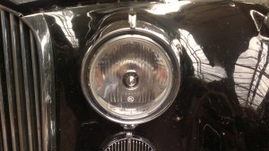
 NL mark on Lucas 51507A PF 700 vertical dip
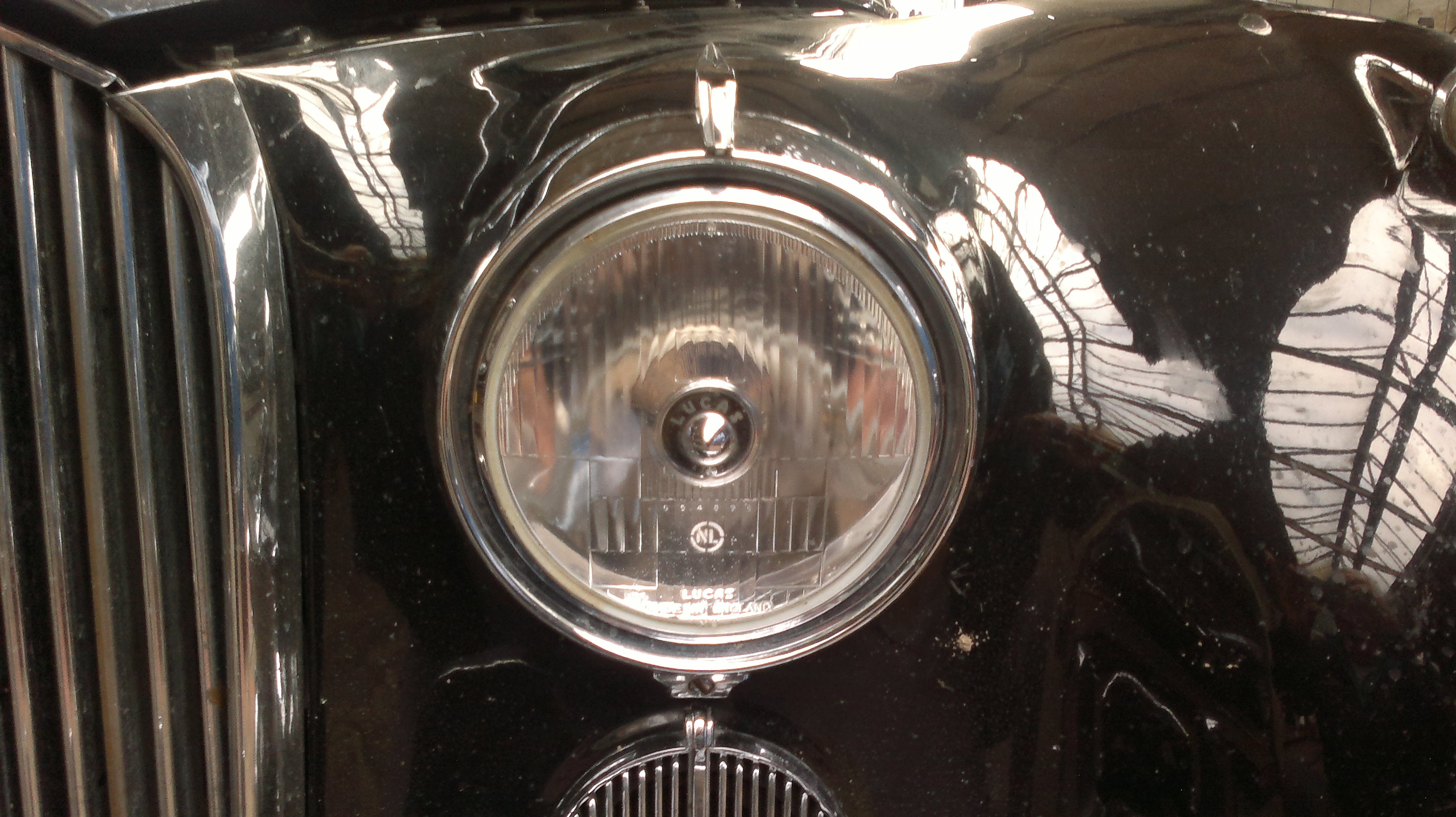
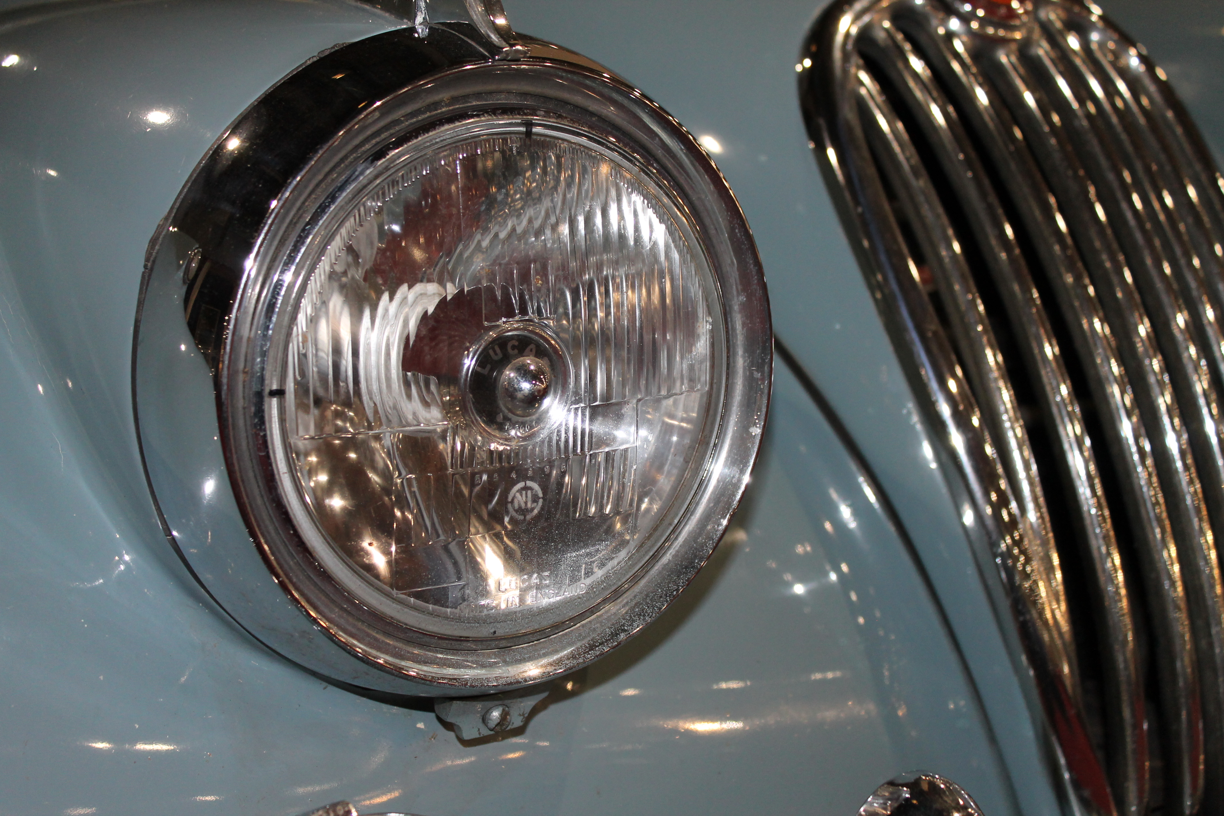
Lucas 700 Continental 553940 with NL mark
The Lucas Le Mans 24 light unit 554665 was therefore sent to KEMA in Arnhem to obtain the NL type approval and it successfully accomplished all tests. If we look at Jaguar only, this particular light unit was not only used in Holland, but in (at least) 4 other countries (Norway, Sweden, Germany, Switzerland) and we should not forget other countries like Belgium (163 XK140 and XK150 in total), Italy (47) and Portugal (18) that have not been mentioned specifically in the Spare Parts Catalogue. Lucas supplied the same light unit to other British car manufacturers so the total production of the 554665 light unit must have been several thousands.
The NL mark is the only “visible” national approval mark that we know on headlamps (apart from the later “E mark” for Europe). We should not exclude that the Dutch approval mark was accepted by other countries that had some form of cooperation with KEMA.
KEMA was (and is) a leading European (ISO certified) laboratory in the area of electrical safety and the KEMA approval mark is still found today on many electrical products. Today electrical safety schemes in Europe have a similar cooperation model (named ENEC) whereby the approval testing outcome of one member country is accepted by the other EU countries.
France also had a national homologation system for headlights for automobiles. The French Ministerial Decree of 8th October 1929 formulated new regulations for car lighting, becoming effective per 1st May 1930. According this decree all cars shall have lighting equipment that should be able to:
- Light the road over 100 metres (indicated with the letter A)
- To suppress any blinding, without ceasing to light the road, when encountering other road users (indicate with the letter B)
All headlights developed to fulfil the above requirements will be investigated by a committee of the Ministry of Public Works (Travaux Public) to receive a conformity mark mentioning e.g. Agréé AB (Certified AB). All headlights mentioning Agréé AB are followed by the letters TP (Travaux Public) and the number of the certification of the homologation (№ 123) issued by the committee.
Like the NL mark etched in the front glass for The Netherlands and Switzerland on Lucas 51565A/B headlights, the French version had a similar etched marking reading Agréé AB-TP № 457 in a dashed rectangle to show conformity to French regulations
In 1976 the new European Regulation76/761/EEC on “motor-vehicle headlamps which function as main-beam and/or dipped-beam headlamps and to incandescent electric filament lamps for such headlamps” became mandatory for all EEC member states. This replaced the various national regulations in action so far. It is also clear now that the 1976 production of the Le Mans 24 headlamps was merely aimed at replacing existing Le Mans 24 light units or for special race applications, because this (outdated) optical concept could never fulfil the newly developed requirements, nor was there a commercial interest for Lucas to do so. Therefore the need to have the NL mark on these light units was no longer there and the E mark (replacing national approval marks) was out of reach.
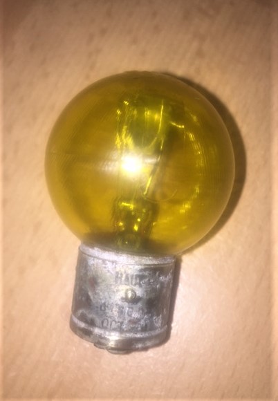
Jaguar XK Windscreen Washers in detail
-
Introduction
Jaguar used windscreen washer equipment manufactured and supplied by Trico Folberth Ltd, of Brentford, UK for their entire XK range (either standard on SE/MC models or optional on standard models). Next to Trico another UK company, Tudor, provided windscreen washer equipment to British carmakers (e.g. BMC), but Tudor was never used on Jaguar XK’s. Both companies became important suppliers of equipment to the British motor industry but also sold directly to the public in the form of “aftermarket” accessories.
Trico had been established in about 1917 (initially named the Tri-Continental Corporation) with manufacturing facilities in Buffalo USA, as a company that specializes in windshield wipers and other automotive equipment in particular related to vacuum powered systems. Trico acquired Folberth (of Cleveland, Ohio) in 1925 which company had been manufacturing vacuum wiper systems since 1919. Thus Trico became Trico-Folberth.
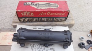 Late 1920’s Trico-Folberth product
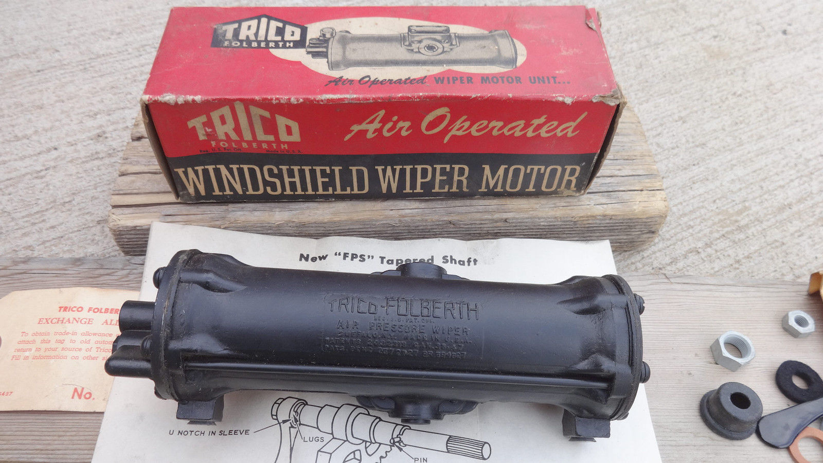
As early as 1928 Trico-Folberth Ltd. opened a UK plant in Brentford (and a second one after the war) where it manufactured a large range of products (windscreen wipers & washers, switches, cigar lighters, etc) for almost 7 decades until the late 1990s. Trico relocated its UK operations to Pontypool, South Wales where it still resides today.
 Trico factory in Brentford in Art Deco style
Trico-Folberth also established manufacturing facilities in Australia in 1958 as a supply basis for Australia, New Zealand and in fact the whole of South-East Asia.
Jaguar’s relation with Trico-Folberth ended with the introduction of Lucas electrical washer equipment in the early 60’s. The complete system including jets, T-piece and hoses was now provided by Lucas. They are not further covered in this article.
 Trico-Folberth 1951 advertisement

-
Trico Part numbers in UK and USA
As Trico windscreen washer equipment existed already in the USA years before Jaguar introduced their XK 120, most washer parts have an American origin. Trico USA used a coding system with 5-digit part numbers (with some exceptions) and these have been taken over where possible by Trico-Folberth in England. In addition Trico-Folberth UK developed a number of parts specifically destined for the British automotive industry, like Jaguar.
To make a distinction in “corporate Trico parts” and UK specific parts, Trico-Folberth UK used a prefix “X” in front of the 5-digit “corporate” parts and introduced 6-digit part numbers for UK specific parts, all in the 700000, 800000 or 900000 range. This applies to both new UK assemblies (often using US components) as well as new UK components.
Also note that Trico UK commercial washer model indications started with XAW followed by number and suffix. “X” stood apparently for “Universal” applications, but when specific assemblies per brand were made Trico UK often used the first letter of that brand: e.g. the Windscreen Washer Assembly for the XK 120 had the commercial indication JAW12-3. A Ford version was called FAW6-30 and those for Vauxhall were named VAW9-20 etc.
 Early US Trico washer systems

When looking at Washer equipment for Jaguar XK’s, the fact that (1) Trico was both active in the USA and UK and (2) the vast majority of XK’s went to the USA, meant that through the years many Trico windscreen washer systems in XK’s may have become an amalgamation of (original) UK parts and US (spare) parts. The same situation may have developed in Australia where local parts (e.g. glass bottles and labels) could have been used as spare parts for original Trico UK products.
This article tries to clarify what is original Trico/Jaguar equipment and what may have been added/changed using other Trico (UK, USA or Australia) parts over the past 6 decades.
-
Trico Spare Parts
Spare parts are becoming (very) scarce, although some complete products are being remanufactured nowadays. At some autojumbles you may be lucky enough to find that part you’re looking for (instead of buying a complete new complete product). Trico spare or service parts were available at almost any garage in the 1960’s. The photos below show an example of a Trico UK spare part box and content of around 1970; it was coded Trico XAW-101A.
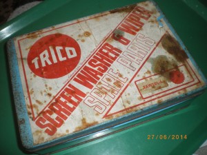
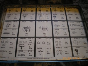 Trico XAW 101A
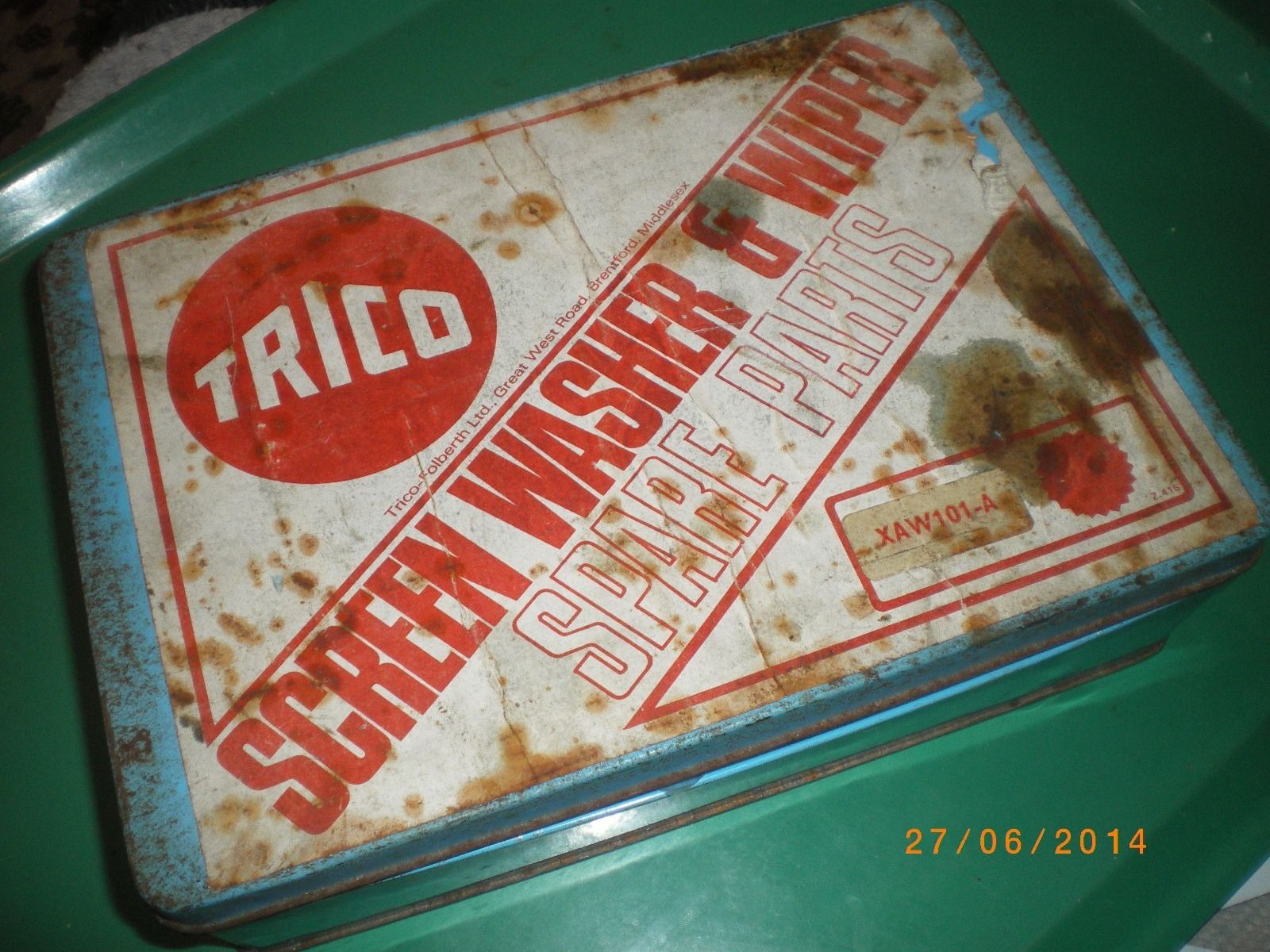
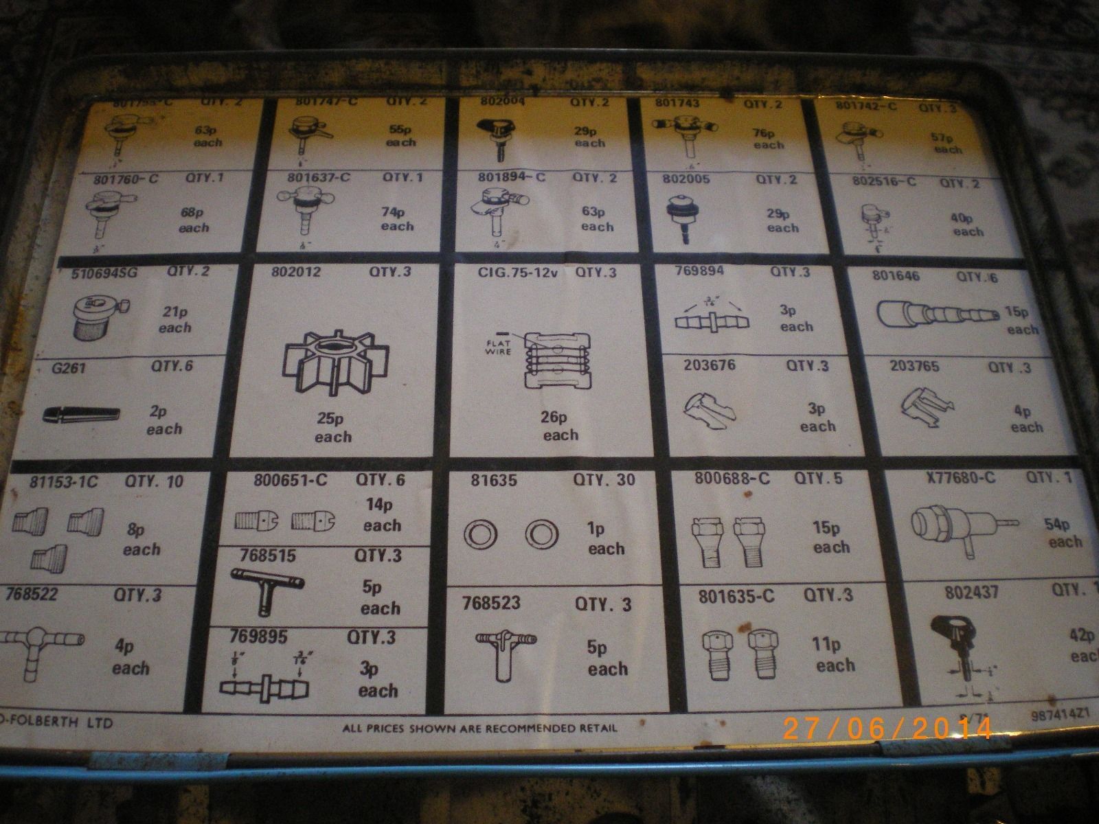
-
The XK Windscreen Washer system
The Trico system uses vacuum from the inlet manifold to (eventually) spray washer fluid on the windscreen. Functioning of the Trico washer system in short: when the Trico control button on the instrument panel is operated, underpressure moves the rubber diaphragm up, sucking fluid from the reservoir and filling the casing; after the control button has been released the vacuum is removed and the atmospheric pressure plus the compression spring above the diaphragn forces the fluid out towards the washer jets (as a valve blocks the way back in the reservoir).
 Trico washer pump schematically
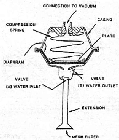
The complete Windscreen Washer Assembly of the XK 120 DHC and FHC (comprising everything required for a complete installation) had Jaguar Part Nº C5472 and Trico Part Nº 800010, but more interestingly a commercial type number JAW12-3, which translates as a Jaguar-optimised version of the universal XAW12-3 Washer system. This unit had a “Jar, Pump and Bracket Assembly” with Jaguar Part Nº C5473/1 and Trico Part Nº 800008.
The XK140 OTS and DHC models continued the Trico washer unit of the XK 120 (though with some minor changes like rubber hoses). The complete Washer unit for the XK140 OTS and DHC had Jaguar Part Nº C5596 but no Trico type number is given by Jaguar. We can safely assume however that Trico continued the XAW12-3 type coding. Also the same “Jar, Pump and Bracket Assembly” with Jaguar Part Nº C5473/1 and Trico Part Nº 800008 was continued for the XK 140 OTS and DHC.
 The parts of a Trico Windscreen Washer Assembly

Trico UK also provided a complete system solution for the installation of a Windscreen Washer unit in the XK 140 FHC. This unit had Jaguar Part Nº C9178 (and Trico type coding XAW6-2 or possibly JAW6-2 as we will see later). Heart of this unit is the “Jar, Pump and Bracket Assembly” which for the FHC had Jaguar Part Nº C9179 and Trico Part Nº 800076.
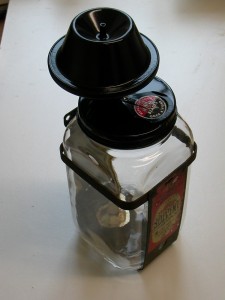 FHC bottle, pump & bracket assembly Jaguar C9179
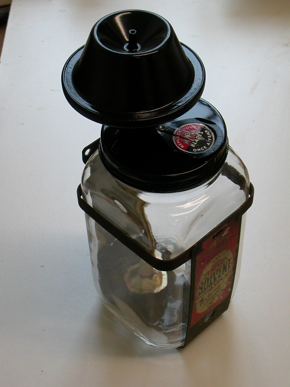
The windscreen washer version of the XK 140 FHC differs from the OTS and DHC version because (as Porter mentions) “probably space was tight” in the engine compartment and therefore a (smaller) square bottle had been chosen instead of the (larger) round version as used for the OTS and DHC. We can confirm that the “tight space” was indeed the reason for this change, as also Trico used this as an argument when positioning this bottle configuration in their programme (see below). Later in the 1950’s Trico-Folberth UK offered the XK 140 FHC washer solution as a standard version for the “aftermarket”. It was now called the “XAW6-2 Universal Model Small Jar type….. for cars where fitting space is extremely restricted”. See below left.
 XAW6-2 (from 1960 Trico UK catalogue)

Note: Trico also offered the XAW6-2 washer system for some British Ford cars, as can be seen below. There exists thus a (very small) possibility that some of these Trico square bottle washer systems have survived in a (British) Ford of the late 50’s or early 60’s.
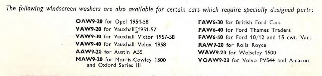
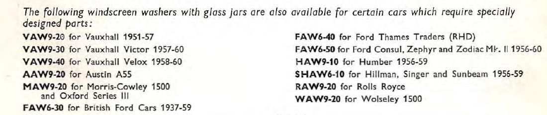
The XK 150 received a different washer system Jaguar Part Nº C14334 and probably Trico JAW9-2. The bottle, pump and bracket assembly had Jaguar Part Nº C10127/1 or Trico Part Nº 800051. The pump was now located within the glass bottle but the rest was left unchanged. This version (C10127/1) was also used on the various Jaguar Mk 1 versions; the Mk2 switched over to a Lucas electrical windscreen washer version.
 XK 150 washer system Jaguar Part Nº C14334
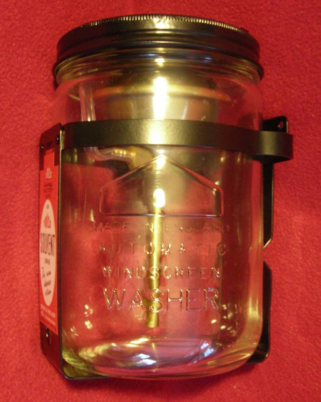
Trico-Folberth offered the “XK 150 windscreen washer equipment” also as an aftermarket accessory in the late 50’s: Trico part number XAW9-2 (see photo below) looks fully identical to the above XK 150 version. Or did Jaguar simply choose an already existing standard Trico UK version for their XK 150 series in 1957?
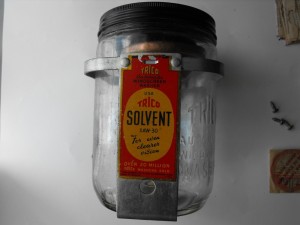

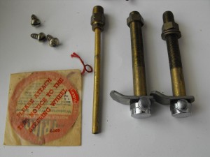 XAW9-2 as “aftermarket” kit

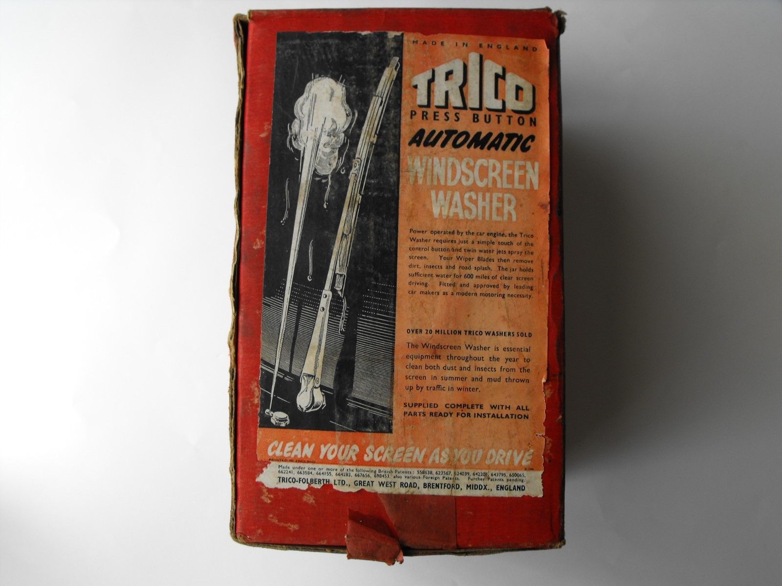

-
The glass bottle
Much has been written on the Trico glass bottles for all versions, except for the FHC glass bottle (or “Jar” as Jaguar and Trico called it). It received Jaguar Part Nº C9184 and Trico Part Nº 800037, a specific Trico UK part number. The bottle does not have “TRICO” moulded into the glass. Trico UK also offered the square bottle type for (British) Ford cars (as is stated above) probably in an endeaver to increase the production quantity for these bottles as only 3000 bottles just for the Jaguar XK 140 fixed head coupes is hardly an attractive production figure.
The glass bottle for the XK 140 FHC has the following text (sometimes difficult to read) casted on the bottom side: B & Cº Ltd K at the top of a (quarter) circle with a large figure (here “24” but also “3” has been observed) in the middle. At the lower part of the circle on the inside of the bottom we find the indication P 112.
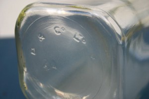 Text on bottom of square Trico bottle (courtesy: Roger Payne)
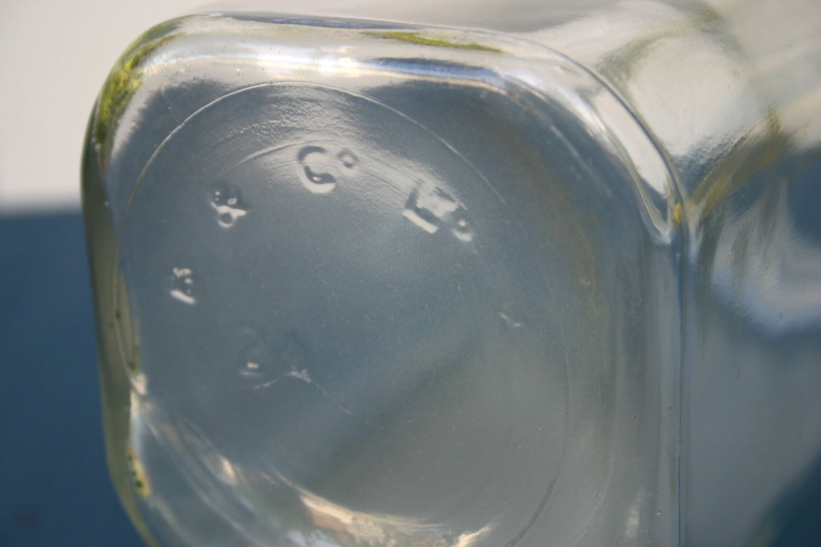
This lettering most likely refers to the company Bagley & Co., Ltd. of Knottingley, Yorkshire, England (1898-1962), a company that produced bottles in large quantities but is also known for its “glass art” (vases, etc). In 1962 it was acquired by the Jackson Brothers (or the Jackson Glass Co.), another local Knottingley firm. The Rockware Glass Co., in turn, took over the Jackson operation in 1964. This company remained in business until 1975.
We also have also seen bottles for the XK 120 and the 140 OTS and DHC (Jaguar Part Nº C5473/2 or Trico Part Nº X.78369) that had the same lettering and the number 858B. But also the Trico glass jar (Jaguar Part Nº C10127/2 and Trico 800042) of the XK 150 washer system had the same lettering B & Cº Ltd K and the number S124 (?) as can be seen on the photo below.
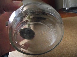 Text on bottom of XK 150 Trico glass bottle

Looking at the time line, Trico most likely had Bagley as one of their glass bottle suppliers. Even the fact that the name Bagley disappeared in 1962, does not conflict with this assumption, as by that year Trico was switching over to plastic bottles and Jaguar had switched over to Lucas for the supply of Windscreen Washers in the meantime.
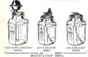 Other applications of the UK square jar
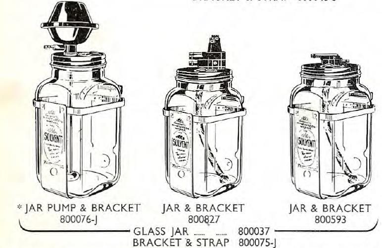
The XK 140 FHC bottle measures 3¾” (95 mm) width and depth and the total height is 7½” (190 mm) whereas the height to the neck is 6½” (165 mm); the washer fluid capacity according Trico is 0.86 litre.
As Trico uses the indication XAW6 the 6 might well stand for the number of Quarter Pints (6 x 0.142 = 0.852 litre); note that Trico also has other Jars with indication XAW9 and XCAW10 indicating a larger volume. The volume of the XAW9-2 is indicated as 2½ pint, but should be 2¼ if the 9 quarter pints should be correct. But the increase to 2½ might well be done for “commercial” reasons.
The cap of the XAW6-2 measures about 3¼” (83 mm). Note that the bracket for the larger round bottles measure about 5” square, meaning Jaguar could save about 1¼” or 32 mm, probably to create better access to the oil dip stick of the FHC. See also the above advertisement: XAW6-2 “Small Jar type”.
The bottles for the XK 120 and the 140 OTS and DHC had Jaguar Part Nº C5473/2 or Trico Part Nº X.78369 which is a standard Trico USA part carried by Trico UK.
The bottles for the XK 150 had Jaguar Part Nº C10127/2 and Trico 800042.
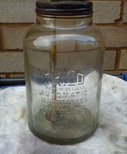 Trico Jar X.78369 for XK 120 and 140 (not FHC)
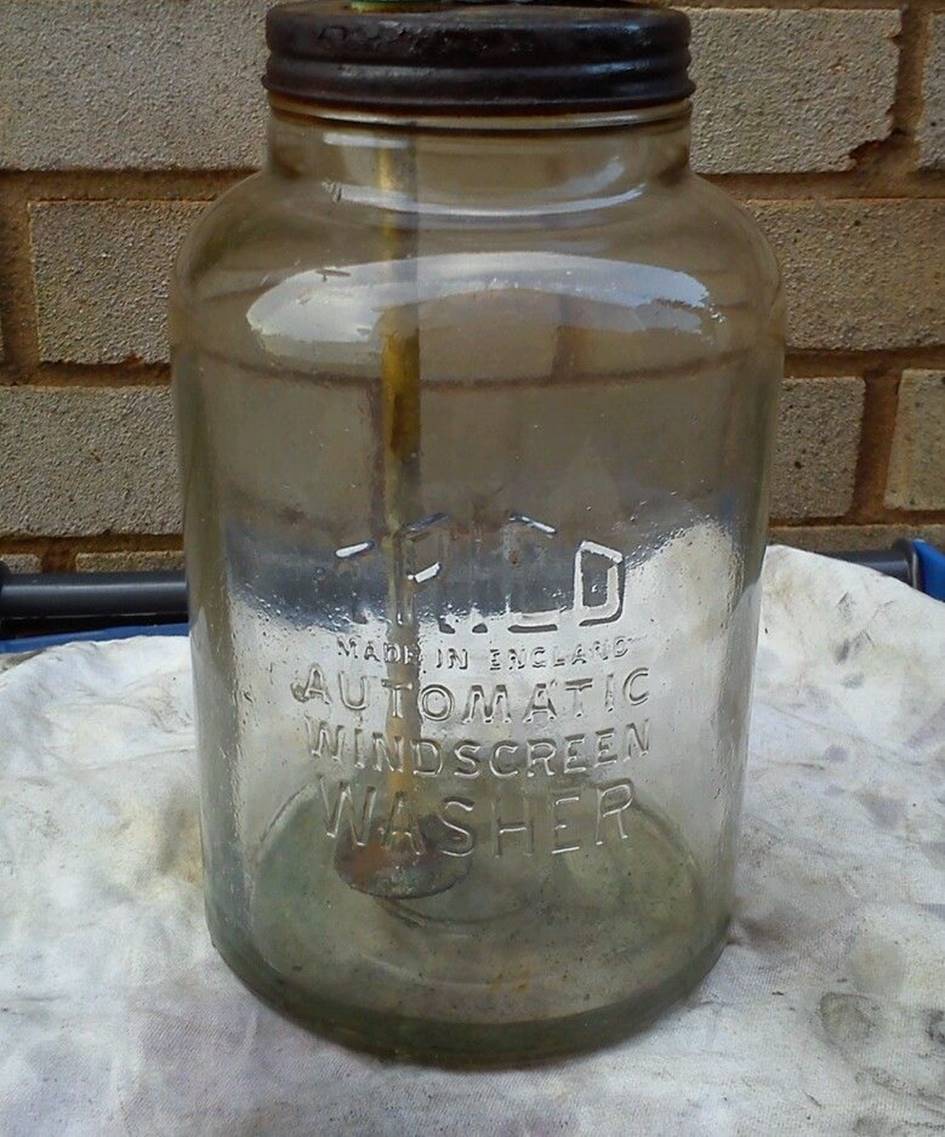
-
The Pump assembly
The Pump including Cover on top of the glass bottle is identical for all XK 120 and XK 140 versions and has Jaguar Part Nº C5473/3 or Trico Part Nº X.82540. The suction tube or Strainer Assembly is also the same for all versions and has Jaguar Part Nº C5498 and Trico Part Nº X.76431/1M.
 Pump, Cover and Strainer XK 120/140

The pump for the XK 150 (and Mk 1) is slightly different as this unit is positioned within the glass bottle and is fixed to the lid on the top of the pump (instead of the bottom of the pump as per XK 120/140). The pump has Jaguar part number C.10127/3. A similar construction is used on the later Trico plastic windscreen washer systems and the vacuum pump may well be interchangeable.
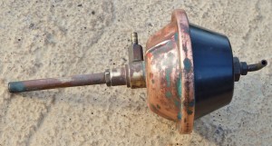 Pump unit for XK 150 (and Mk 1): note the nut on the top of the dome for fixation to the lid.

The lower half of the dome is made of brass. Two types of dome tops have been used by Trico UK for the XK 120 & 140. Both versions are made of high pressure die-cast aluminium;m later domes carry the Trico logo and the following additional text “MADE IN ENGLAND” and “TO CONTROL VALVE”. This is a Trico Folbert UK product evidently. It is evident that the XK 150 dome top is different due to the different location of the pump within the bottle.
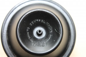 Upper dome version of Trico UK pump

The upper domes of the Trico UK pump were all smooth, whereas Trico USA offered different upper dome shapes for their pumps. Early pumps had a smooth dome with an cylindrical part on top. Later domes had “stiffening” ribs on the side. Both types are unsuitable as a replacement for an original Jaguar washer pump.
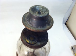
 Early Trico USA pump with different dome shape. (Later) Trico USA pumps have ribs.
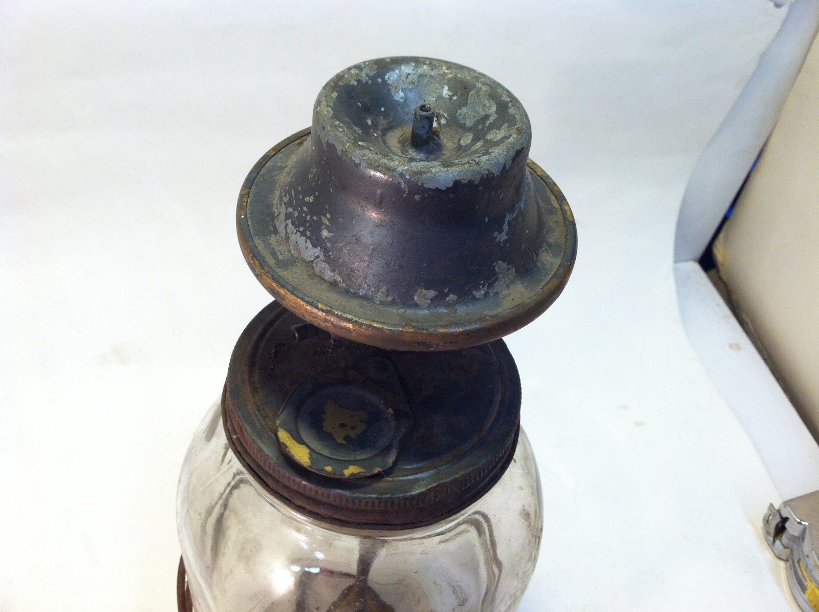
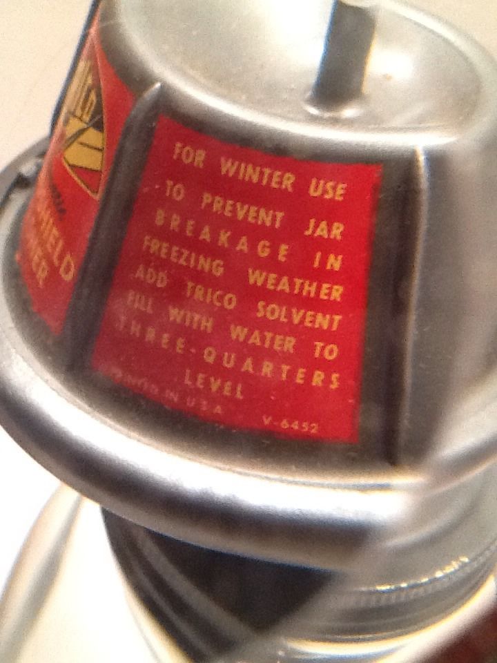
The pump has a “check valve” at the lower connection to the strainer and the tube connection to the washer jets. This “one way” valve consists of a steel ball in the brass lower pump housing. A second check valve is in the hose pillar part (connecting the washer jet hoses).
Check valve in hose pillar to washer jets
The “strainer” consists of a ⅜” copper tube with ⅜” – 32 UNEF thread at the top and (sometimes) a filter at the bottom end. For the XAW6-2 washer bottle the length of the strainer tube was about 6½” (or 170 mm).
The complete pump and strainer were fixed to the bottle cap using a ½” – 28 UNEF nut, selflocking washer and plain washer which were screwed to the threaded lower end of the pump house.
There is a small (brass) lid placed over the washer fluid filler opening that can be rotated aside, The (red and black) round Trico label placed on the lid reads “REPLACE YOUR WIPER BLADES ONCE A YEAR”.
 Label on filler opening lid

There are different lid types. Some versions have a half circle depression and a “reinforcement rib” running towards the rivet with which the lid is secured to the bottle cap. Other versions are flat in this area and have a full circular depression; this type is seen on both early US as UK washer pumps. XKs (120, 140 and 150) use the (older) flat version, whereas the (later?) stiffened version may have been only used for the combined vacuum/electrical versions (synchronizing the washer function with the wiper system).
It looks as if the round Trico label is solely intended for the “flat” lid version with the full circular depression. The “stiffened” version is mostly shown with a different larger Trico label (half circle shape), whereby this label is not positioned on the small lid but elsewhere on the large bottle cap.
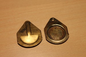
 Different lid versions. Reinforced lid with incorrect label for XKs?

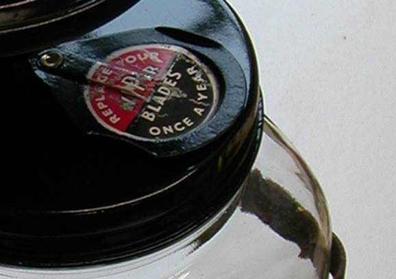
-
The Bracket for the bottle
The Bracket that carries the Trico Windscreen Washer Assembly for the XK 120 and 140 models (except FHC) have Jaguar Part Nº C5473/8 and Trico Part Nº X.78364-IE which indicates that this is originally a Trico USA product. However, bottle brackets made by Trico UK are normally painted black, where as most Trico USA brackets were Cadmium plated.
The Bracket is different for the FHC as is the way it is mounted. The bracket has Jaguar Part Nº C9185 or Trico Nº 800075/E, is square and the glass bottle has a tight fit in the bracket. Again, because this part number consists of 6 digits it is a Trico UK specific part. The Bracket is mounted at the LH side of the engine bay just in front of the brake fluid reservoir: only 3 setscrews (3/16 UNF x ½” with nuts and shake proof washers) are used instead of the 5 for the OTS and DHC bracket.
Further investigation learned that there were actually two FHC brackets, whereby the later version had the “Trico” trade mark, the text “Made in England” and a survey of patents stamped on the inside of the rear steel strip.
 Later FHC bracket C9185 or Trico Nº 800075/E
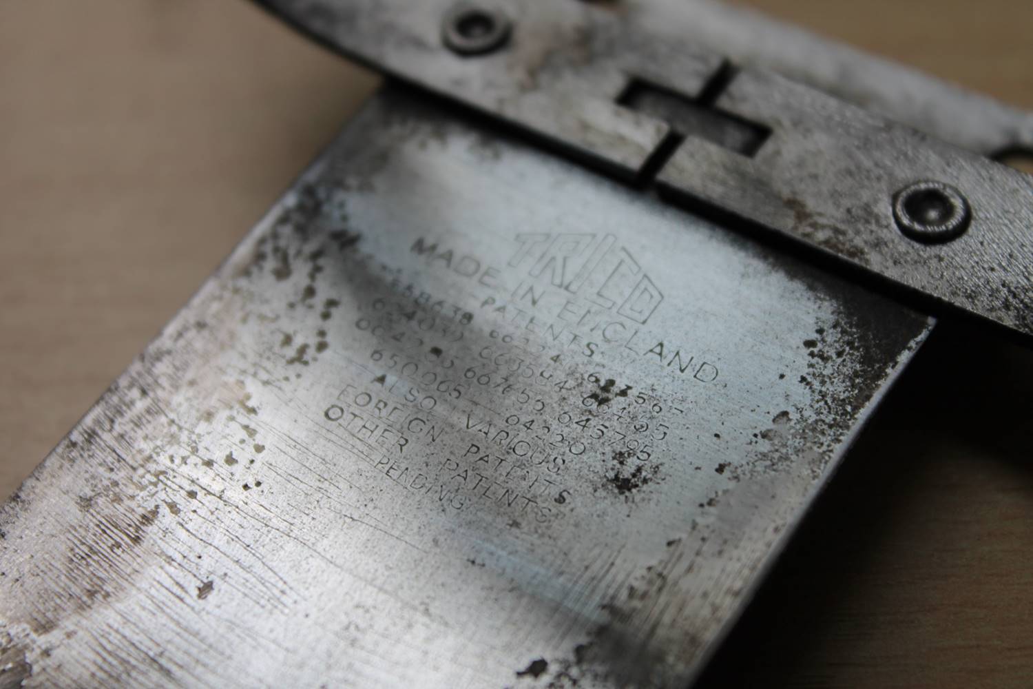
Whether the change-over coincided with the introduction of a new label (see below) is unclear, but the older labels all have brackets without the “Trico” trademark.


Early XK 140 FHC bracket C9185 and later Trico label for info only.
Two different Trico label versions have been used: the above photos show (left) the early version (text reads: 6 oz. bottle XAW-30) and (right) the later version which reads only XAW-30 and has an additional line at the bottom of the label (“OVER 20 MILLION TRICO WASHERS SOLD”).
Trico washer solvent was supplied in various ways: initially glass bottles, later plastic bottles and sachets. The reference 6 oz. XAW-30 on the lable refers to the glass (and plastic) bottle content as supplied by Trico UK. Trico USA refered in their catalogues to the WA-30 6 oz. bottle.
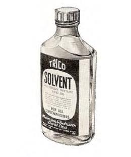
Early glass 6 oz. bottle XAW-30 Later (1960) plastic 6 oz. bottle
-
Rubber hoses
Two diameters of rubber hoses are used for vacuum and washer fluid. Trico had a large range of rubber hoses in their programme (because of their extensive vacuum wiper motor programme) but the sizes of importance for Jaguar XK washers are:
- “All rubber” hoses with ID 7/64″ (2.8 mm) for ⅛” (3.2 mm) connections: Trico Nº F.15. Outer diameter of this hose is 15/64″ (6.0 mm).
- “All rubber” hoses with ID 5/32″ (4.0 mm) for 3/16“ (4.8 mm) connections. Three code numbers have been used for the 3/16“ hose: Trico Nº 618, Trico Nº 846 and later Trico Nº 81846 (converted to 5 digits). Outer diameter of this 3/16“ hose is 5/16″ (8.0 mm).

The Jaguar Parts Catalogue gives a detailed survey of the various tubes used and their position. All vacuum hoses are of the 3/16 “ (4.8 mm) type as is the main washer fluid hose from pump to T connector. The two hoses from the T piece to the washer jets are of the ⅛” (3.2 mm) type. Remember that a vacuum hoses may collapse if the rubber wall isn’t stiff enough: reinforced tubes are preferred but sometimes their (increased) outer diameter may cause problems with the existing rubber grommets, which is why Trico used “all rubber” hoses with a lesser increased wall thickness.
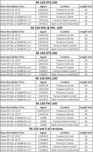 Survey of hose lengths

There are some problems related to this survey: the ⅛” hose C5472/13 (T-piece to LH Jet) for the XK 140 FHC is apparently 26” long (66 cm), but the same part number is also used for the XK 140 OTS version and there it is indicated as 43” long!
Given the position of the Trico reservoir at the LH side of the engine compartment, and given the position of the T-piece at the end of a 24” long hose from the reservoir plus the fact we are dealing here with the LH Jet, a length of 26” is more than adequate for hose C5472/13 (in fact I found it much too long).
Another problem that remains is that the original lay-out of the tubes behind the instrument panel is difficult to retrieve.
-
The Tee piece
The T connection (Jaguar Part Nº C5473/6 or Trico Part Nº X.87223/1) is made of brass and divides the flow of washer fluid from the reservoir to the LH and RH Jet. Jaguar uses Part Nº C5473/6 also in combination with “Tee Connection” Trico Nº X.77689/1, whereby the latter part number is a Trico USA derived number. The main supply hose is 3/16” and the two hoses to the Jets are of the ⅛” type, which translates in a special T piece with unequal branches. Later T-pieces are made of plastic and the correct (unequal branches) plastic version has Trico UK Part Nº 768523.

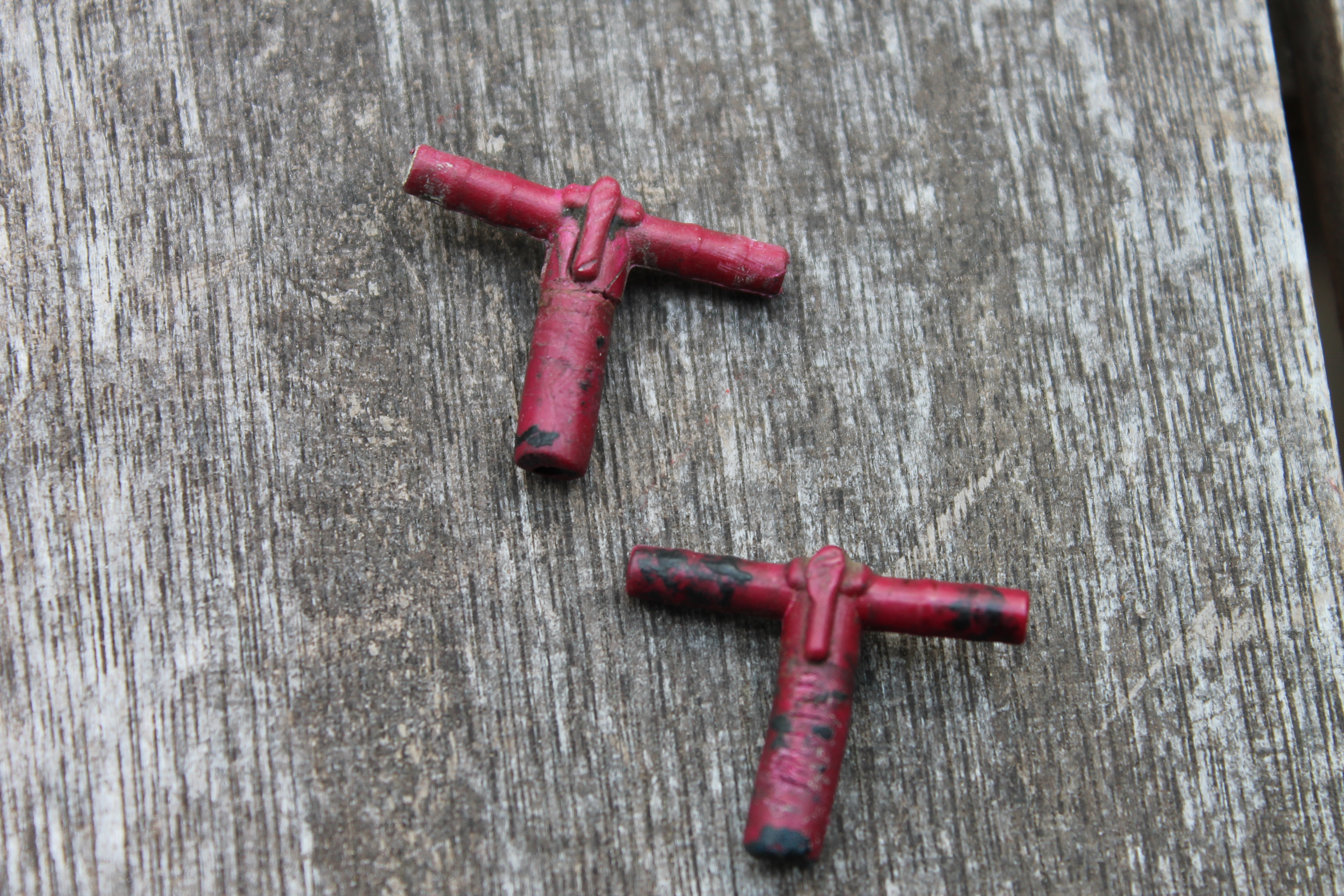
Trico T-piece X.87223/1 or X.77689/1 Later Trico T- piece 768523
-
The Washer Jet System
The original Washer Jets are well described by e.g. Viart / Payne in their book “XK 140 explored”. These Washer Jets were continued from the XK 120. The chosen threads for jets and housing clearly show the American origin of these Trico windscreen washers as some destine from the pre 1950s so even before the “Unified” era in the USA started.
There are in fact two different Washer Jets assemblies that look similar but have a different hose pillar diameter. The one applied by Jaguar has an 1/8″ diameter and is described hereafter. The other version has a 3/16″ hose pillar diameter and is coded by Trico UK as Part Nº 801894-C. The latter requires different rubber hoses (now all 3/16″) and T-piece (all branches 3/16″: Trico Part Nº X649-1 in brass or Nº 768515 in plastic) .
The chrome plated Trico washer jet assembly named “Easy-Clean Jets” (with Jaguar Part Nº C5473/4 or Trico Part Nº X.78778-C but later also Trico Nº 801742) is basically built-up from three parts: (1) Main body, (2) Washer Jet and (3) Knurled Button.
 Original washer jet less knurled button

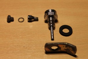 “Exploded view” of the complete washer jet system
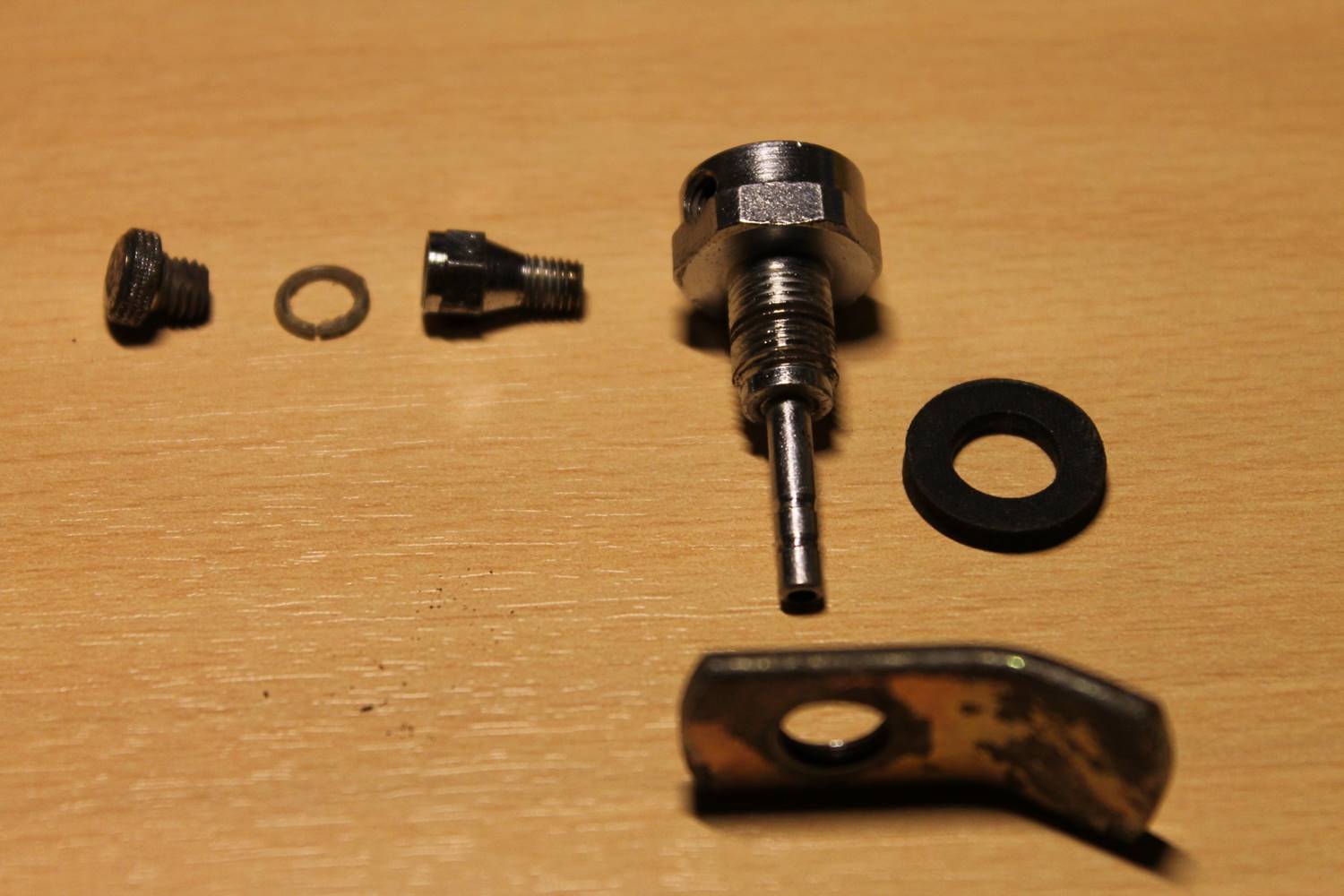
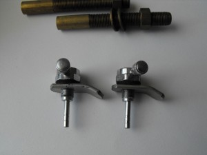 Washer jets and extension tubes in XAW9-2 kit

-
The Jet Body
The main jet body including the hose connection and threaded lower part, used a bended steel piece that acts as a nut to install the complete washer jet to the car. This nut (“wing nut” according Trico) has Trico Part Nº 76624). Trico (USA) part number for the main body is 78779-3C. Thread for the fixation of the body to the car is National Extra Fine 5/16 -32 NEF or later UNEF. A rubber washer (Jaguar C5497 or Trico 75172) is placed between the jet housing and the car This is a 1.5 mm flat rubber washer with 3/16” or 8 mm ID and 5/8” or 16 mm OD .
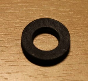 Rubber washer Trico 75172

-
The washer jet itself
The washer jet (including knurled button) with Jaguar Part Nº C5495 or Trico 81600-C, which is screwed in the main jet body, has a tiny slit/opening at the hexagon end which allows the washer fluid to be sprayed in one specific direction, once the closing button is in place. The special thread of the washer jet (and internal thread of the washer body) is apparently National Special Nº 8-40 NS or later UNS (about Ø 4.2 x 0.64 mm).
The below part of the washer jet has Trico Part Nº 81151-1C and is used both by Trico USA and Trico UK.
 Washer jet, shown here without knurled button

The below shown Trico jet with the round spray hole in the centre of the hexagon part, fits perfectly in the main jet housing and is closed with a different button. Trico USA assigned Part Nº 86022C to this washer jet (or “nozzle”) and positions it as a full alternative for Trico UK washer jet Nº 81600-C using Trico USA Part Nº AW-128 for both alternatives. Some XK’s may have switched over to this US alternative (like mine).

 Trico USA 86022C


-
The knurled button of the jet
The jet is closed with a knurled Button (Jaguar Part Nº C5499 or Trico Nº 81153-1C) which screws into the jet; thread is National Fine NF10-32 (comes close to 2BA). The button thread has two flats to allow fluid to flow to the opening. This Button can be removed for cleaning the jet opening (“Easy Clean” jets). There is a small sealing ring between de button and the jet (Jaguar Nº C5496 or Trico Nº 81635) . There are buttons with and without the Trico brand logo, but apparently the original buttons did not have that Trico logo.
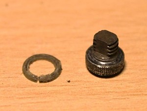 Knurled button and sealing ring

-
Alternative (contemporary and later) Trico washer jet assemblies
Although BMC mainly used washer equipment from Tudor they applied a similar Trico solution for some of their high-end brands in the late 50’s and early 60’s like e.g. MG ZA/ZB series, Riley and Wolseley cars. These washers however had a different, smaller washer housing: the cylindrical and hexagon part of the main body have different dimensions compared with the Jaguar solution. The washer housing was originally fixed to the body with “wing nuts” instead of hexagon nuts. The washer jet itself is identical to the Jaguar version (Trico Nº 81600-C ; here with Trico logo).
 BMC used Trico for their “high-end” brands

Other Trico washer jet assemblies are available, but they have either hexagonal or conical bodies in which the jet itself is screwed (see photos below). They are not particularly suited as a replacement for the Jaguar XK windscreen washers if originality is required.
 Unknown version with smaller hexagon housing

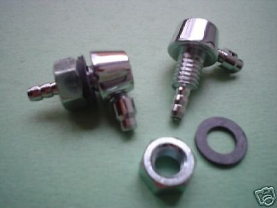
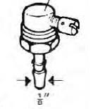 Trico 802516-C (1970s)
Trico also delivered “Twin Jets” to be used in a central position in front of the windshield. An earlier Trico version was coded 801743 C and used two “knurled buttons” (Jaguar Part Nº C5499 or Trico Nº 81153-1C). The introduction of this version probably dates from the mid 60’s (photo below left). A later (70’s) introduction was Trico Twin Jet 803274 C (photo below right) but this version doesn’t have the “knurled buttons” as used for the earlier Jaguar XK’s.

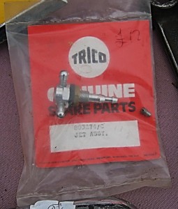 801743 & 803274
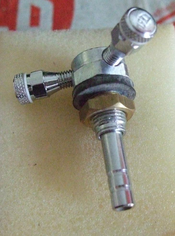

-
The Control Button
The Control Button (when pushed) activates the vacuum in the system and when released the washer jets spray washer fluid to the windscreen. Trico apparently made a special version for Jaguar (and possibly some other high-end brands) because of the (thick) wooden instrument panel this button was built in.
There are many types of Control Buttons in the Trico programme, with a split-up in two main types: (1) controls with parallel hose connections and (2) controls with one 90° hose connection. There are indications that the “90° controls” are the oldest (USA 1940’s onwards) and were still available in 1980. The “parallel controls” may have been a Trico UK development and were (relatively) short-lived but still referred to in 1960.
The length of the button also varies: the majority of the Trico Washer programme uses Controls with very short buttons that cannot be used for the (thick) Jaguar XK instrument panels. There are three versions with a longer chrome plated button and these are the ones used in XK’s: the longest one (32 mm) is of the “parallel”, but there is also the same length available in the “90°” controls type. and finally a shorter one (24 mm) iof the “90°” controls type as well. These buttons are nowadays a rare find.
The “long” button version of the “90° connection” category has a total length from (back of the) nut to end of button of about 24 mm. This one fits the XK dashboard and the majority of the XK 120 and 140 versions have this button type. This control has (most likely) Jaguar Part Nº C5472/7 or Trico Nº 900306, which means UK specific.
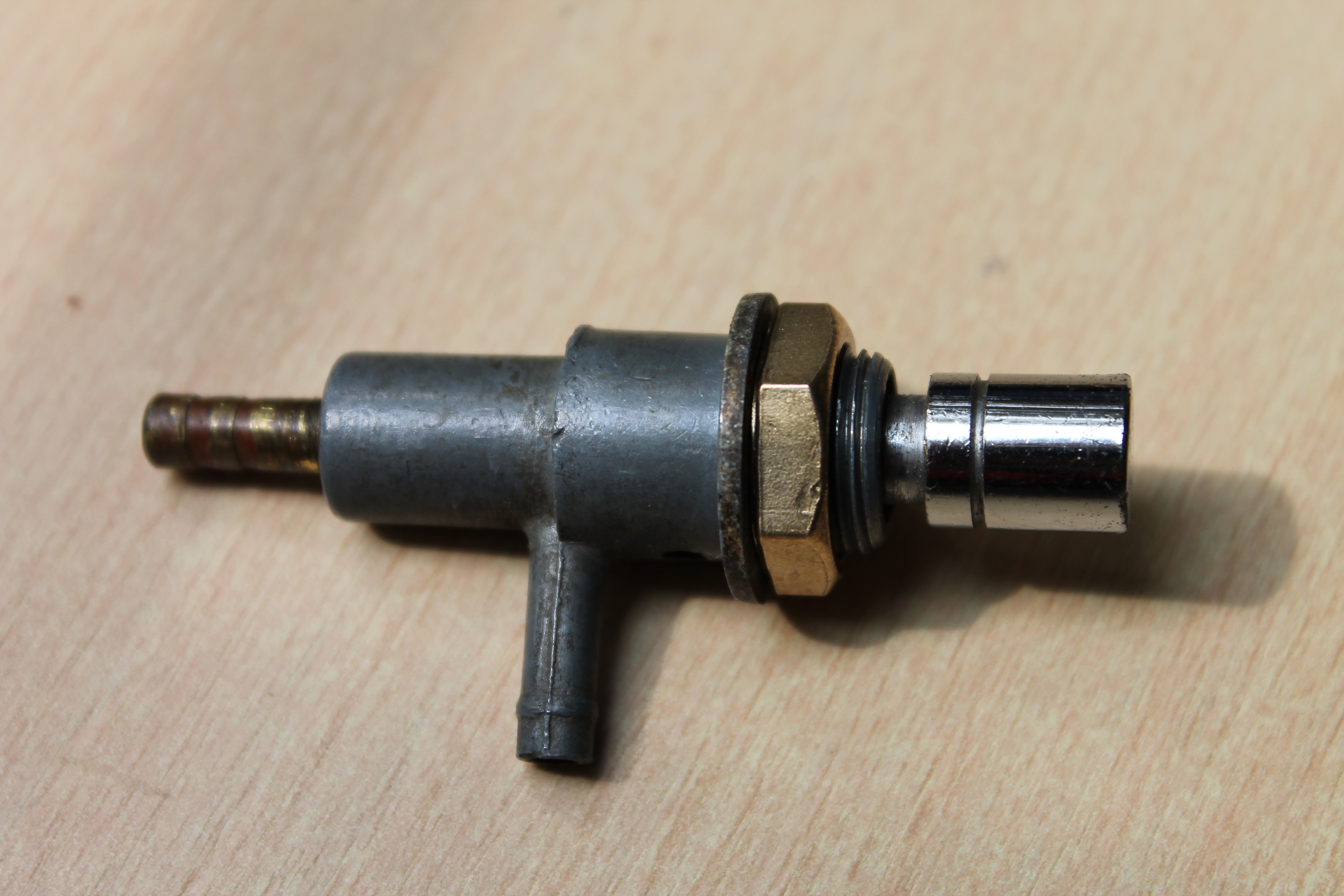 24 mm long Control Button Trico 900306 (or 900106)
Note: the XK 120 DHC and FHC may have had a different Control Assembly: although the Jaguar Part Nº C5472/7 was continued from the early XK 120 down to the last XK 150, the Trico part Nº for the XK 120 was 900106 (whereas the XK 140 had 900306). We should, however, not exclude an error in the Jaguar Spare Parts Catalogue.
The below Control Button of the “90°” type has a total button length measured from the (back of the) nut to the end of the button of about 32 mm (1¼ inch). Product data are not known![]() , but the button seems fully identical to the version described hereafter.
, but the button seems fully identical to the version described hereafter.
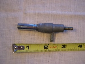 32 mm long control button “90°” type

The below Control Button of the “parallel” type has a total button length measured from the (back of the) nut to the end of the button of about 32 mm (1¼ inch). This version is possibly related to the Trico 900306 version (see photo above). Product data are not known![]() . This version has also been seen on XK dashboards, but its origin and originality remains unclear.
. This version has also been seen on XK dashboards, but its origin and originality remains unclear.
 32 mm long control button parallel type.

Easier to find is the shorter Trico version of the parallel type, which uses the same body as the above version. However, it doesn’t fit in the Jaguar dashboard. This one is “Made in England” and is used on various “high end” BMC cars like MG, Riley and Wolseley. This product had Trico Part Nº 900255-C, indicating it was indeed a UK specific product. The length from (back of the) nut to end of button is about 14 mm.

 Trico 900255-C is too short


In the category of control buttons with a 90° hose connection, different versions are offered (besides the aforementioned versons with a longer button). A shorter version with a length of about 14 mm has Trico Part Nº X.77680-C and was made by both Trico USA (Part Nº 77680-C from the 1940’s onwards) and Trico UK. This Control Button is installed in a dashboard using a chrome nut (Trico 77679-C) and a washer (Trico 2322J). This version is too short for the XK dashboard.

 Trico X.77680-C; too short


-
The Check Valve
From September 1955 onwards XK140s received a brass Check Valve which was installed in the rubber hose from the inlet manifold to the Control Button. The check valve or “non-return” valve secures that vacuum remains in the washer system (when the engine stops) and the washer jets can do their job (for a short period though). The Check Valve has Jaguar Part Nº C11491 or Trico Part Nº 900292 (UK specific). The original item is apparently rare nowadays and modern replacements are often used instead.
For the XK 150 the Check Valve became integrated in the inlet manifold adaptor: Jaguar Part Nº C13570 or C14715 and thus was no longer a separate item as with the XK 140.
 Original Brass Trico check valve?

-
The Inlet Manifold Adaptor
Vacuum is drawn from the Inlet Manifold via a rubber hose connected to a “Connector” or Manifold Adaptor screwed in the manifold. This Adaptor initially had Jaguar Part Nº C5473/5 (taken over from the XK 120) and from September 1955 onwards C11490 with Trico Part Nº 770750 and 770793 respectively. This adaptor is screwed in the manifold: thread is ⅛”-28 BSP.
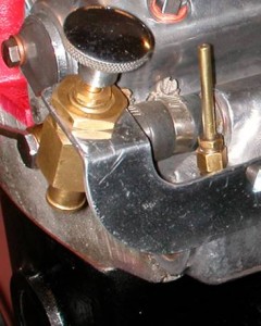 Early inlet manifod adaptor Trico 770750

The XK 150 had the Check Valve integrated with the inlet manifold adaptor: Jaguar Part Nº C13570 or C14715 .
Lucas “Sports” Coil
Lucas “Sports Coils”
Introduction
Many Jaguar XK’s (as many other British sports cars of the 50’s and 60’s) often had a Lucas Sports Coil of the SA12 type installed as an aftermarket accessory, in an attempt to (further) improve the car’s performance.
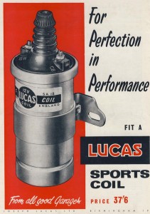 Lucas SA12 Sports Coil advertisement 1960

Although Porter in his book “Original Jaguar XK” refers to this coil as “a 140/150 sports coil” it actually never was available as a Works Option from Jaguar. And as far as I know, none of the British sports cars ever had a Lucas Sports Coil as a factory standard item.
Further investigating the subject of “Lucas sports coils” learned that there are in fact 4 different generations of these sports coils, whereby the so-called “Red Top” SA12 version is apparently the most attractive version.
Why a “Sports Coil”?
An ignition coil is in fact a transformer with about a 100 to 1 ratio between secondary windings (consisting of 6,000 to 20,000 turns) and primary windings (normally about 300 turns). The output voltage will therefore be e.g. 100 times greater than the input voltage.
When the contact points are closed the primary winding of the coil is connected to the battery and draws an electrical current of about 4 amps. The coil core is in fact an electromagnet with a magnetic field induced by the current flowing in the primary winding. When the points open to break the contact, the primary current must stop flowing and the magnetic field in the transformer will collapse. The collapsing magnetic field forces the current to continue flowing in the same direction and that current will charge the capacitor in the distributor. This raises the capacitor voltage momentarily to about 300 Volts, at which time this high voltage stops the current. The current then reverses direction, being driven backward by the high voltage at the capacitor. The initial 300 V spike in the primary winding will induce an output in the secondary winding of e.g. 30 kV (depending on the aforementioned winding ratio).
What type of ignition coil is required for a particular engine depends on the specific requirements of that engine: aspects like C.R. (compression ratio), the chosen sparkplug gaps, etc. have an impact on the required ignition voltage for the plugs to produce an optimum spark. In addition we should keep in mind that ignition coils are strongly affected by the contact breaker, particularly at high speeds, meaning that the contact breaker should be of the right quality if the coil has to deliver top performance. On a six cylinder engine running at e.g. 4000 revolutions per minute the contact breaker has to make and break some 12000 times per minute. At each make and break a starting current (commencing at 4 Amps or so and falling away to about 1.5 Amp as speed increases) has to pass across the points without appreciable voltage drop, if the coil is to build up a maximum spark voltage during the very brief time the contacts are closed.
Standard Lucas coils normally deliver an ignition voltage of 20 to 30 kV. A “High Performance” coil and more in particular a “Sports Coil” provides an increased voltage of about 40kV or higher, because of the different relation between the number of windings of the primary and secondary windings.
Two different manufacturing methods over the years
Regarding the manufacturing method of the coil housing or “can” we see a clear split-up in the earlier “assembled” housings made of (zinc plated) steel with soldered seams and bottom versus the later aluminium cans made via a process called “cold impact extrusion”, a method also used for the manufacturing of large capacitors. Lucas introduced this process around 1950 also for the SA type of Sports Coil. Note the “expansion” groove at the lower part of the aluminium cans, which is made to prevent the can to burst in case of an excessive overheating of the coil. If the coil expands an internal safety mechanism will cut the voltage supply and prevent any further temperature rise of the coil.
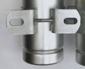 Expansion groove in SA type aluminium can
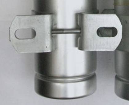
Later Lucas branded aluminium cans no longer have this expansion groove. There are more complaints reported of coil “decapitation” due to thermal problems with these later coils, whereby the coil normally bursts at the top and the oil will spread throughout the engine compartment (see photo below).
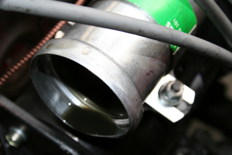
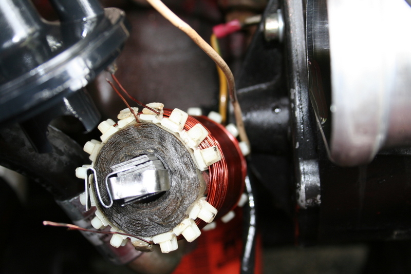
This is what might happen with an overheated coil (later type) without an “expansion groove”.
1. Lucas HS type Sports Coil from late 1930s
 Lucas catalogue 300E from 1937
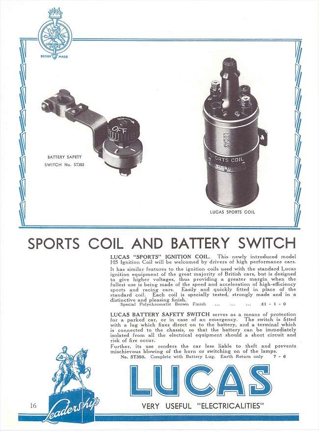
This first generation Sports Coils coded HS was developed by Lucas as early as 1937 in a 6 Volt and 12 Volt version. It started as a black coated version with a brown Bakelite top. It may have been not available for a number of years until 1950 when it became available in a grey painted housing. We refer for this to the Lucas advertisement of April 1950 introducing the new grey coloured Sports Coil in which Lucas states: “Motorists will welcome back the Lucas Sports Coil”. A survey:
1.1 First version HS coil
The black HS6 and HS12 coil had a brass Lucas type plate, which was fixed to the clamp with 2 screws. All HS coils are marked SW (ignition SWitch) and CB (Contact Breaker points) for the 12 Volt circuit connection. The Lucas part number was 406996 for the 12 V version and 406997 for the 6 Volt version. These part numbers remained unchanged for all HS coils although several development changes took place.
The text on the brass plate reads: MODEL HS12, TYPE L-0 12V ER 45038A but other (pre-war) plates refer to the Lucas part number 406996 for the HS12. Lucas catalogues indicate that coil 45038 has been replaced by coil 45058 in the early 50’s. ER stands for Earth Return meaning no separate earth connection but the can itselfs acts as connection to earth. The type number of the HS6 version is 45037A.
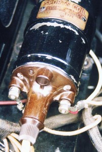
 Lucas HS12 type # 45038 and part # 406996


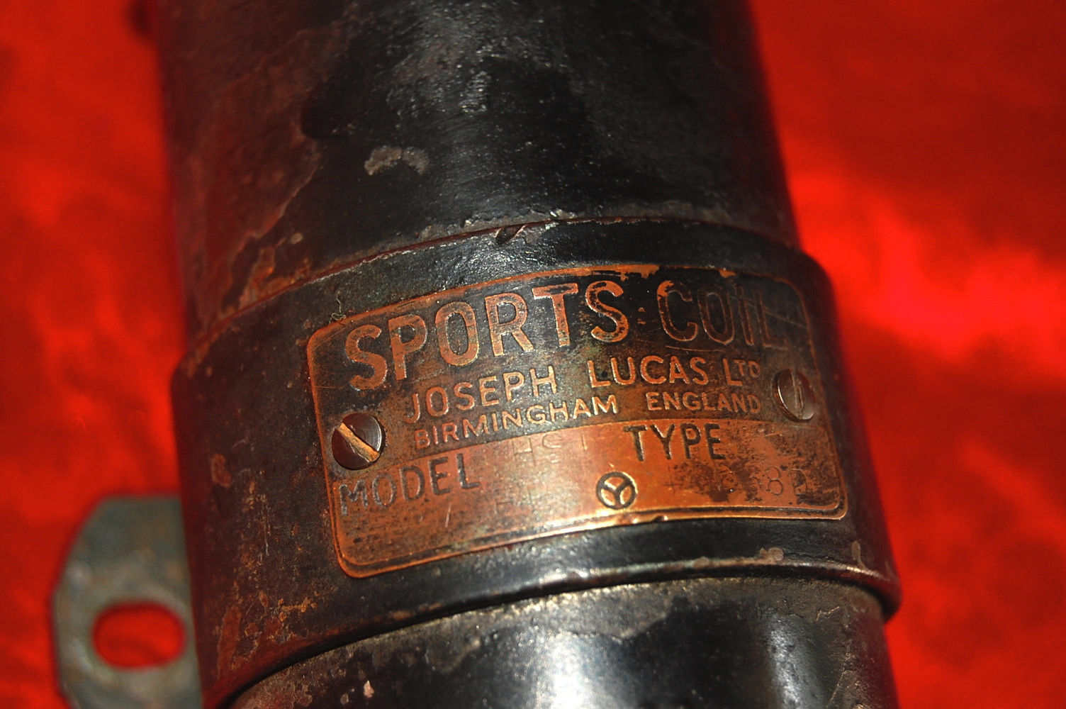
Early Lucas HS12 Sports Coils with brass type plates
1.2 Second version HS coil
Early 1950 saw the introduction of a grey-brown painted HS coil, initially with a black metal plate fixed with 2 slotted CSK screws. The housing was painted in grey-brown which Lucas called “polychromatic brown” (like the colour “polychromatic grey”, a colour they used for many products like the HF1748 horns). This coil was available in both 6V and 12V.
The part number of this coil versions remained unchanged (see 1.1)
 Advertisement April 1950

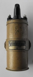
 HS12 12V ER
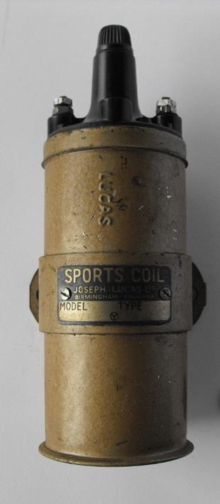
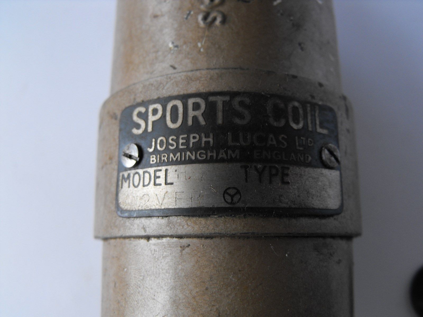
1.3 Third version HS coil
Later (but still in the early 50s) this coil had the label glued to the coil clamp. The label was mainly aluminium coloured with a black band at the bottom. Code numbers changed for unknown reasons from 5 to 6 digits:
- Lucas HS6 Type L-0 45037A Part # 406997
- Lucas HS12 Type L-0 45038A Part # 406996


Lucas 6 Volt Sports Coil. Model HS6, Type L-O, Lucas part number 406997 with printed label.
2. The SA series Sports Coil from early 50s
Around 1955 a second generation with a larger diameter aluminium can and different Bakelite top was introduced which was commercially named SA. This coil was still manufactured until the end of the 1970s.
Lucas SA Sports Coils can be easily recognised by their particular colour of the top part (red-brawn: these coils are also called “Red-tops”) and the special moulded Nut 422792 for the screwed connection of the HT cable to the central contact of the distributor cap; this nut differs from the one used on all other Lucas coils with a similar connection type.
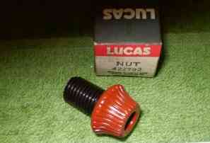 Special SA coil nut 422792
The diameter of Sports Coils is with 61 mm about 3 mm larger than a standard (LA or HA) coil. The clamp (or “Saddle” as Lucas calls it) is therefore also special and has part number 423947.
 November 1957 advertisement

Two versions have been made:
- Type number SA12 with part number 45058A to M for the 12 Volt version.
- Type number SA6 with part number 45065A for the 6 Volt version.
2.1 SA12 Sports Coils
Three different 12V connections have been applied by Lucas:
2.1.1 The early 12 Volt versions (coded 45058A to E) have screw posts and two nuts (2BA) for the 12 Volt wires coded 166043. These coils are marked SW (ignition SWitch) and CB (Contact Breaker points).


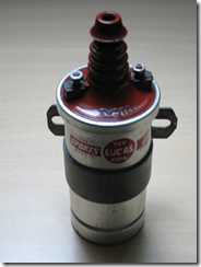
2.1.2 Later 12V Coil versions starting from suffix F (about December 1959) were supplied with one “LUCAR” single connector (54190096) and one double connector (54190108) that could be installed on the two (2BA) studs using the existing nuts (still leaving the possibility to use this coil on older cars with eyelets). This was done because many manufacturers had meanwhile switched over to the LUCAR kind of connector for their car production. These coils were still marked SW and CB.
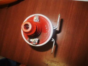 Second version with optional LUCAR connections
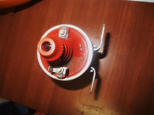
2.1.3 Final 12V versions with suffix K to M (commencing 1968 running till 1978) had double LUCAR connectors riveted on the top, which no longer allowed the use of eyelet connectors. At the same time the marks SW and CB were replaced by + and – also because most cars had meanwhile switched from positive ground to negative ground.


2.2 Lucas SA6 Sports Coils
Below some examples of the 6V version, in this case a later version with double (riveted) Lucar connectors.


2.3 Lucas Overseas Production
Lucas manufactured in the various parts of the Commonwealth for the “Overseas” markets. In Australia and New Zealand local manufacturing of Sports Coils started in the 50’s or 60’s.
In Australia a special version of the SA type of sports coil was manufactured in the 1960s. It was coded SH12 and the part number was 45088A. When we look at the construction of this coil, the involvement of Lucas UK was evident: apart from the formal Lucas part number for this Australian product, the product made use of a copy of the early “red top” (including the special moulded nut 422792 of the british SA series) although most likely with a different outer diameter for the top allowing the use of an already locally manufactured aluminium can of the HA type (probably also the reason to call this coil type SH and not SA). A specific Australian label was added as was the local packaging.
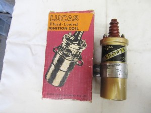 Australian made SH12 coil, manufactured Sept 63

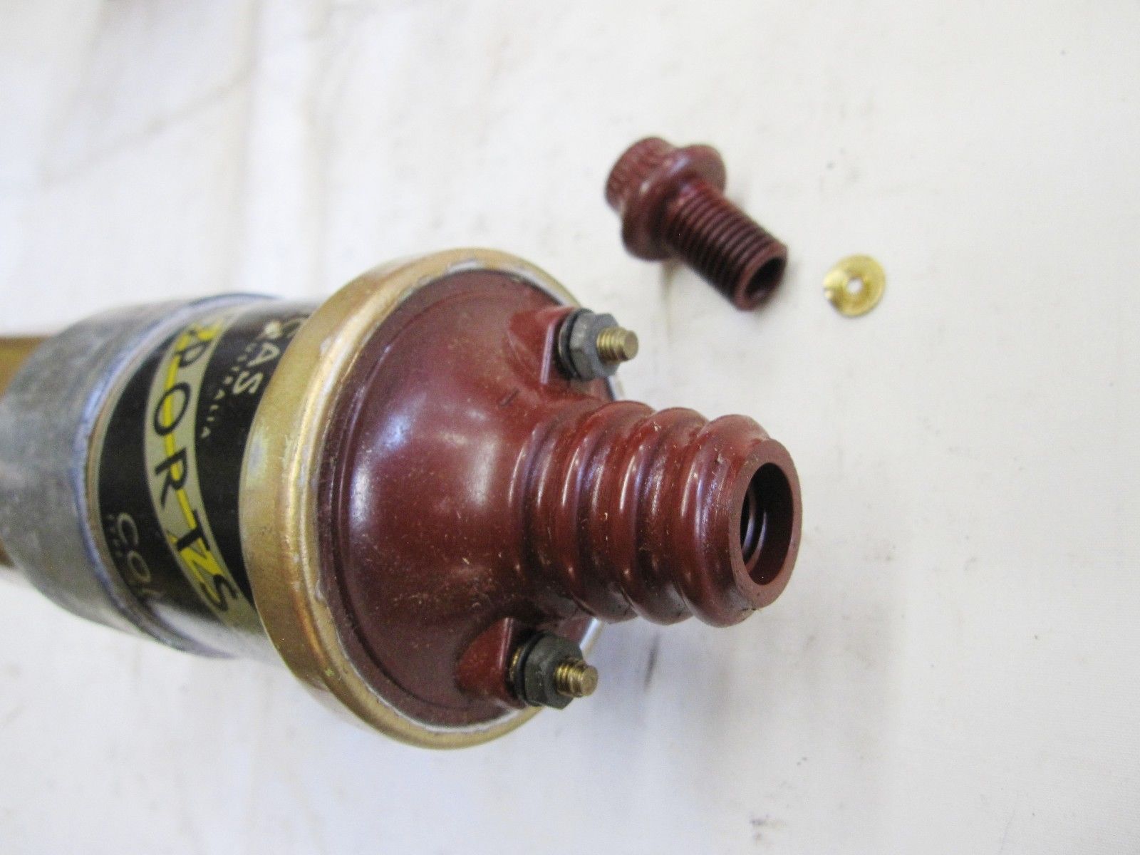

In the 1970s Lucas New Zealand manufactured a Sports Coil with type number SA12 for their home market. Lucas part number was 63206301. This was based however on the standard coil (which has a smaller diameter than the SA12 as manufactured by Lucas UK).
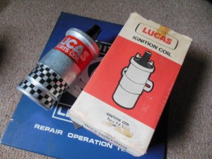 SA12 Sports coil made by Lucas New Zealand

Furthermore it had a black top in stead of the famous red top and the Lucar double contacts as well as the lettering (+ and – ) was in line with the final SA12 production in the UK (see above). Also the label was completely different from the SA12 production in the UK. The performance data of this version are not known.

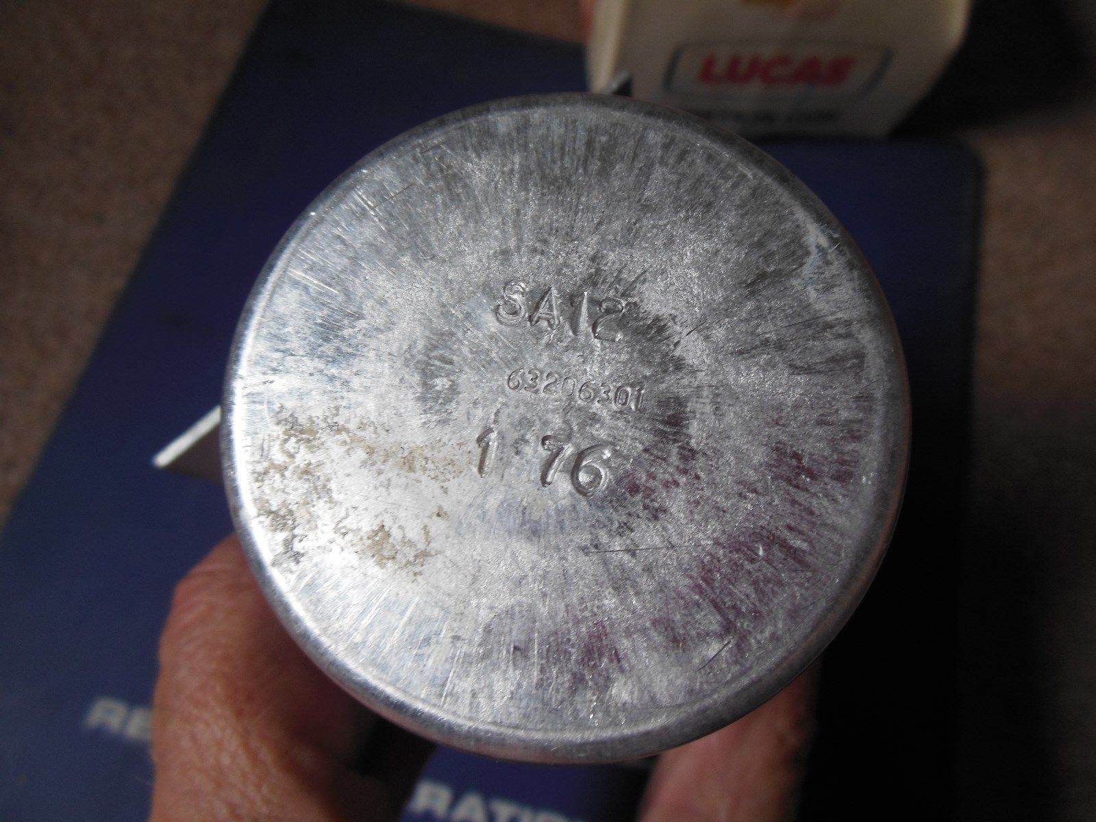
2.4 Lucas High Energy Coils (HE6 and HE12)
An additional version has to be mentioned here which was not called a Sports Coil, but offered identical advantages. The High Energy Coil was offered in 6 and 12 Volts from the early 1950’s as an accessory. It is mentioned in the 1953 Lucas Catalogue of Quality Electrical Equipment. This fluid cooled coil has a die-casted Aluminium housing (heat sink) and a unique bracket with the Lucas logo in blue. Note the top that is identical to the SA Sports Coil with a screw-in type high tension connector and screw posts for the primary terminals.
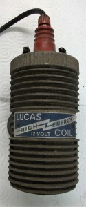 Lucas High Efficiency Coil HE12
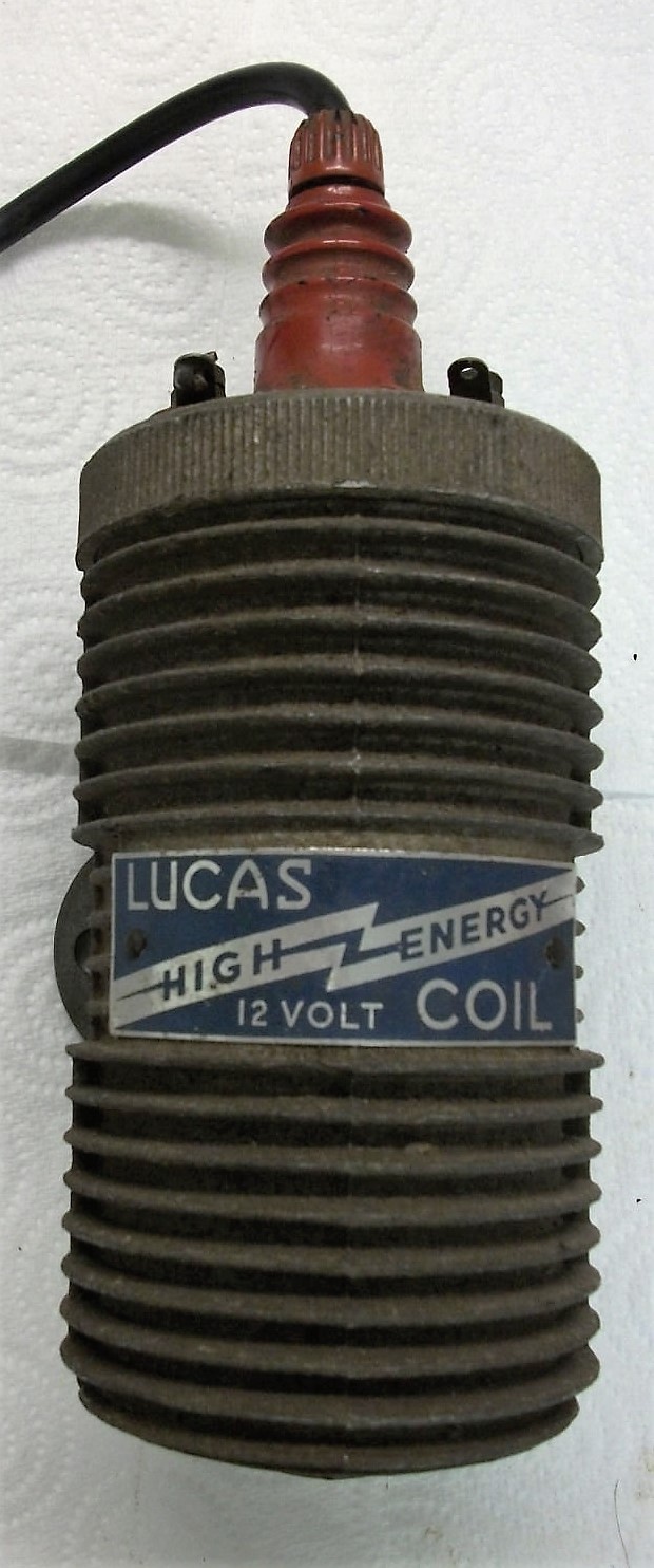
3. PA series “High Power” Sports Coils from late 50s
Introduced in late 50’s or early 60’s, this type of sports coil used the standard housing of the HA type High Performance Coils and not the (larger) housing of the SA type of sports coils. In addition it no longer carried the HT lead connection by means of a “moulded nut and split washer” but changed over to a “screw-in” connection for the HT cable to the distributor cap. The PA series were part of the Lucas range, not replacing but in addition to the SA series over the period 1960 – 1980.
Lucas issued a leaflet “Instructions for fitting sports ignition coils models PA6 (6 volt) and PA12 (12 volt) export only, SA6 (6 volt) and SA12 (12 volt) home market” which might indicate the relation between the two product ranges. The reason for this might be that the non-UK (read “non-Lucas”) car industry used HT cables connected by means of a system whereby the (core of the) cable was screwed into a thin threaded stud. Due to the dominant position of Lucas in the UK it could continue the SA series with the “moulded nut and split washer” connection.
- Sports Coil fluid cooled 12V PA12 Part # 45118
- Sports Coil fluid cooled 6V PA6 Part # 45119
 PA6 Sports Coil Lucas 45119

4. The SP type Super Energy Sports Coil from late 70s
A fourth generation Sports coil (also known as the Gold Sports coil) was introduced around 1978 with the type code SP. The commercial code was:
- DLB 105 for the standard Super Energy Sports Coil
- DLB 110 for the “ballasted” version of the same coil (50% lower resistance of the primary windings)
There are (at least) three different versions of this coil.
4.1 The SP12 Super Energy Sports Coil with Silver label (late 70s to late 80s)
Early coils had a white top with double LUCAR connections riveted to the top. The SP12 coil had Lucas part number 45288A (at least initially) and had a silver label with “12V Super Energy Sports Coil” printed. Note that these early SP12 versions had an “expansion” rim at the lower end of the housing, in line with the housing of the SA series.
 Earlier SP12 45288A 1980

4.2 The SP12 Super Energy Sports Coil with Black label (late 1980s)
A later version of the 1980s (now also named DLB105-B) with part number 45341A had a white top, but now with a black label positioned on the clamp and no longer on the housing above the clamp. The abbreviation B.Y.S. (manufacturer code?) was added in the numbers stamped on the bottom of the coil. These coils went back to the screwed Lucas low volt terminals which allowed to use this coil also for the classic eyelet connections. These coils have most likely been manufactured from late 1980s till about 1996 when Lucas was sold to a US company.


B.Y.S SP12 45341A from 1987
4.3 The SP12 Super Energy Sports Coil with Green label (since September 2004)
Following the return of “Lucas Electrical” in the UK market the DLB105 / SP12 “Gold” sports coil was continued, however with a green Lucas label on the coil clamp.

Probably the most recent version is a 40 kV Sports Coil made with a black top and with removable “Lucar” connectors, opening the possibility to have eyelet connections as well. Also note that the clamp has now “open” mounting holes.

Checking a Sports Coil
Start by checking the resistance of the primary winding. Whereas about 3.2 ohms is standard for an un-ballasted ignition system, about 1.5 Ω is standard for the ballasted ignition system, but the primary coil resistance of a Sports Coil should be 2.5 to 2.7 Ω which is somewhat lower than that of standard coils. The secondary coil windings have a much higher resistance.
|
Coil type |
Primary resistance Ω |
Secondary resistanceΩ |
|
Standard Coil Q-12 |
4.39 |
5190 |
|
Standard Coil LA-12 |
3.3 |
8250 |
|
Sports Coil SA-12 |
2.6 |
10050 |
|
Sports Coil SP-12 |
3.2 |
8660 |