Category Archives: 08. Steering
Horn Push fixation on XK 140 and 150
Leave a reply
Horn Push fixation on Steering Wheel for XK 140 and 150
The Steering Column Control (Jaguar C.5531) is a Lucas manufactured assembly of a Top Cover with Lucas code 32902/E.

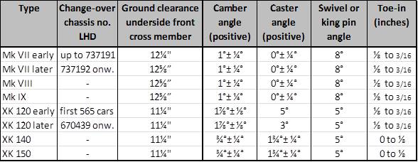
 Top cover assembly Lucas 32902/E Fixing Plate (Lucas 330614) at underside of assembly
Part of this assembly is a Plate for fixing of Control (Lucas 330614) made of (zinc?) plated steel sheet of about 1 mm.
 Exploded view of Lucas assembly 32902/E with position of Plate for Fixing of Control 330614.
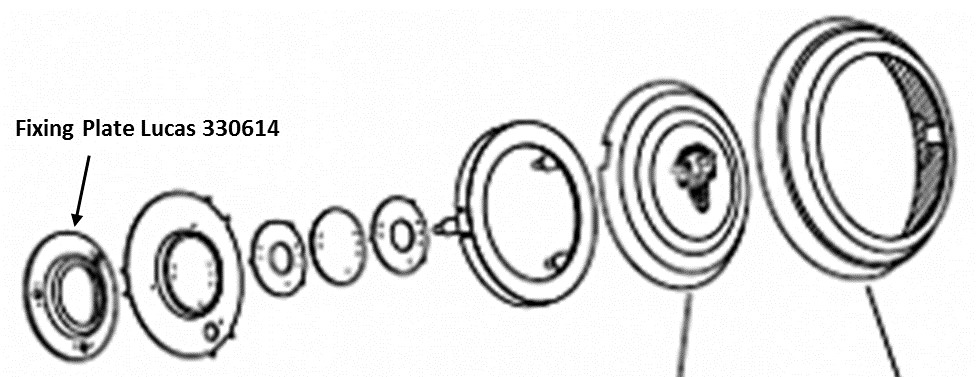
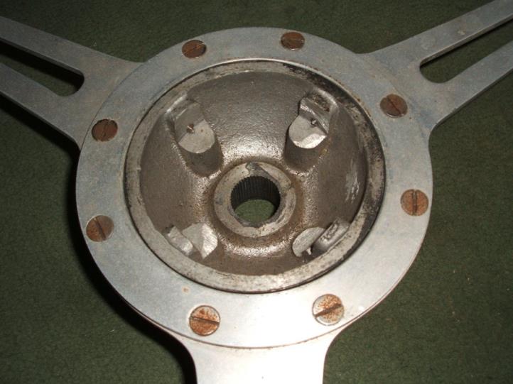
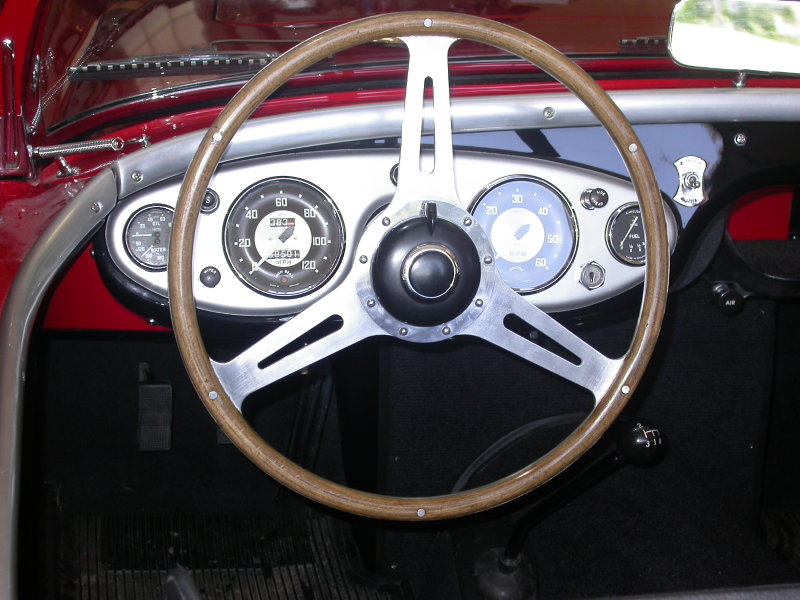
The complete assembly is fixed to the Steering wheel via this Plate 330614 by means of 4 Grub Screws C.1037 on the standard wheel and often 3 Grub Screws on wood rim steering wheel hubs. This Grub Screw has a part number that dates from 1938 or earlier.
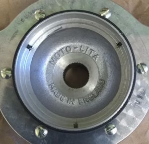
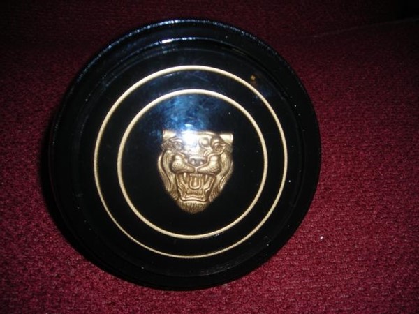
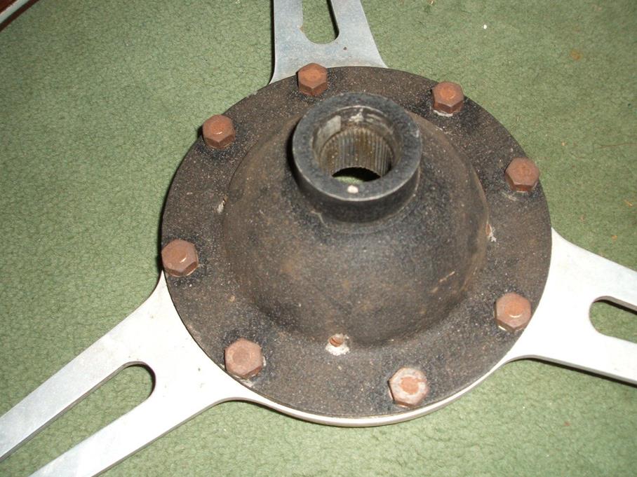
 Example of steering hub with rim for Fixing Plate and 3 Grub Screws
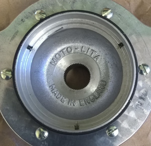
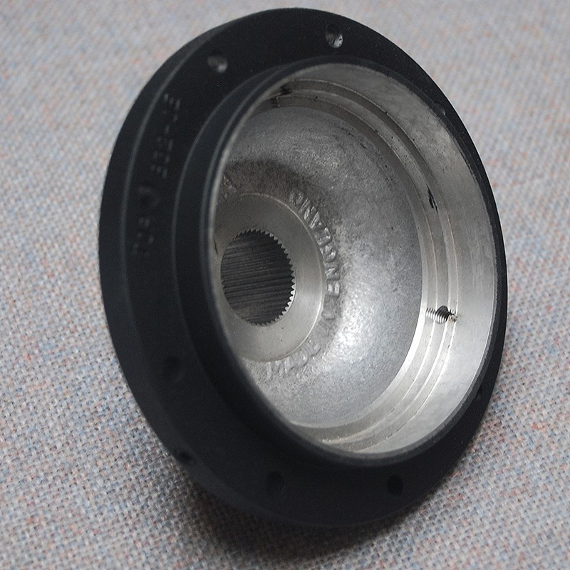
The Grub screw has a hexagonal socket to be used with an “Allen” key (or “Inbus” in most countries) and a pointed tip. The point should hold the Fixing Plate in position whereby the 45⁰ angle should push the Plate down on an internal rim in the Steering Wheel centre (see photos above).
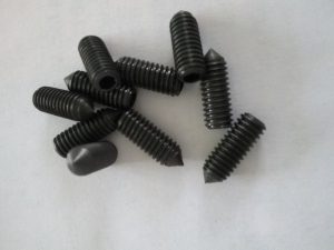 Grub screws with hexagonal socket and pointed cone

The original thread of the Grub screw is difficult to determine, but there are only 2 possibilities considering for this Grub Screw:
- 2BA Diameter 4.70 mm Pitch 0.81 mm Often used by Lucas
For reference the data of the following threads:
- UNF 10 – 32 Diameter 4.83 mm Pitch 0.79 mm Later introduction of UNF
- M5 Diameter 5.00 mm Pitch 0.80 mm “Continental” thread, not UK
The grub screw has an overall length of about ½ inch. Roger Payne mentions a length of 7/16″ but this might be experienced as a bit short as the complete grub screw normally enters far into the screw thread. Note that the original screw may well have been replaced meanwhile by another type. Especially “Imperial Grub screws” are not easy to obtain, but they are still out there.
The UNF 10-32 Grub Screw may be an alternative in the USA. The pitch is again 0.79 mm but the diameter is a little bit larger with 4.83 mm.
Fortunately, an M5 version is readily available everywhere and can be used as a replacement after the thread has been re-tapped with M5. This is feasible as the thread pitch is identical within 0.01 of a mm. Therefore, only the diameter of the threaded hole is increased from (worst case) 4.70 mm to 5.00 mm. The metrical version is readily available: search for DIN914 M5 x 12 or M5 x 16 as an alternative. They use a 2.5 mm Allen or Inbus key.
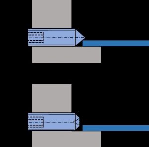 Only the Cone point (top picture) secures the Fixing Plate in a reliable way
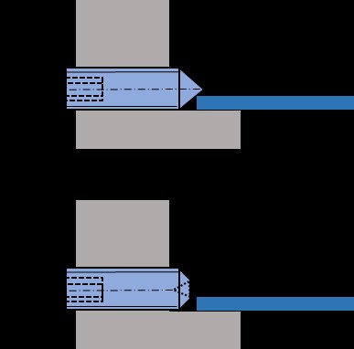
There are basically two types of Grub screws with hexagonal socket: with “Cone” point or ”Cup” point. The above picture makes it clear that this construction absolutely requires a “Cone” pointed version.
Derrington steering wheels 1950’s
Derrington steering wheels for 1950’s Jaguars
This article attempts to summarise (in a structured way) information published on the subject of Derrington steering wheels, gathered from various sources.
Chapter 1 The Derrington company
V.W. Derrington Ltd. has been established around 1919 in New Malden, Surrey, England (about 12 miles south-east of London) initially tuning motor cycles of that era. By 1926 they moved to nearby Kingston and became successful in developing and supplying tuning components like manifolds, exhaust pipes, cylinder heads, and other mechanical improvements for automobiles as well as luggage carriers. From 1933 onwards Derrington advertised with steering wheels as part of their business activities.
Victor William Derrington had been a (motorcycle and automobile) race driver himself for many years, allowing him to exploit his racing experience for developing tuning equipment.
After WW2 there were two “fast runners” made at the Derrington works at London Road in Kingston: Derrington luggage racks and Derrington wooden steering wheels available for many models of the 1950’s and 1960’s. According to “Motor Sport” magazine of December 1959, Derrington employed at that moment eight people full time in the production of steering wheels.
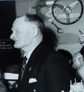 Vic Derrington at the 1961 Racing Car Show; note steering wheel at display

Note that over 60% of Derringtons production was exported, the majority to America. The steering wheels were especially popular in the States and several hundreds have been exported every year from about 1953 onwards. Orders for the USA could only be supplied through their West and East Coast agents: Vilem B. Haan in Los Angeles (CA) and Wilco of Rochester (NY).
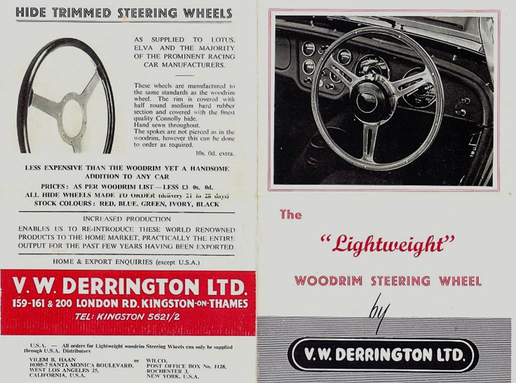
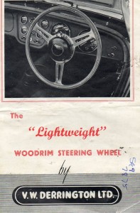 Front of a 1960 brochure

Chapter 2 The “Derrington wheel” and similar wheels
Although Derrington made steering wheels with various spoke configurations, the company became famous for one particular model that we now call the “Derrington wheel”. The specification of (and additional information on) the “Derrington wheel” is provided in Chapter 3.
As production volume increased, Derrington started to outsource some of the steering wheel activities. By the end of the 1950’s another steering wheel manufacturing company Moto-Lita was capable of providing “Derrington” steering wheels, however it is believed that Moto-Lita made wheels in those days were not of the same high quality as Derrington manufactured wheels.
We may assume that Derrington gradually moved away from steering wheel production, fully concentrating on their successful tuning activities. Probably in the late 60’s Derrington completely ceased their steering wheel production activities and Moto-Lita continued the manufacturing of the typical “Derrington wheel” however always characterised by their standard nine hole centre mounting (see Chapter 4).
A similar wheel was offered by the Donald Healey company for their (Austin-Healey) sports cars, which may lead to confusion. This wheel is therefore further described in Chapter 5.
Finally, the name Derrington is often linked to a Jaguar woodrim steering wheel that was available as an option for the Mk 2. However, this was not the “Derrington wheel” but a different model as is described in Chapter 6.
This brings us to the following timeline for the Derrington (style) wheel:
- 1953/54 onwards: the “Derrington wheel” manufactured by Derrington in 15, 16 and 17” diameter
- 1955 onwards: Donald Healey manufactured “Derrington style” steering wheels
- 1959/60 onwards: Moto-Lita manufactured wheels for Derrington (and Donald Healey)
- 1960 onwards: Jaguar Mk 2 Derrington steering wheels (different style with non slotted spokes)
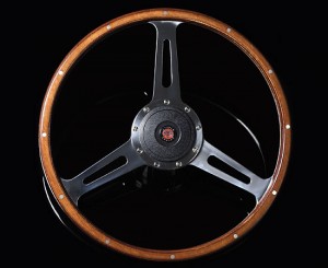
Chapter 3 The “Derrington wheel” specification
Around 1953/1954 Derrington started the manufacture and delivery of the “Derrington wheel”. The design itself shows some resemblance to an earlier Italian manufactured Nardi model with three slotted spokes, however not with the characteristically 3 x 120° even spacing of the Derrington wheel.
Derrington had a patent applied for the making of wooden steering wheels on October 18, 1954 and granted on October 5, 1955.
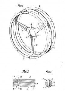 Original patent application of October 18, 1954

Specification and characteristics of the original “Derrington wheel”:
- three (slotted) “Birmabright” aluminium spokes with even (3 x 120°) spacing
- flat (non-dished) version
- eight-hole centre mounting with 8 flat CSK slotted screws and nuts (BSF 3/16 – 32 ?)
- laminated rim from mahogany and either obeechi or white sycamore
- (nine or) twelve rivets in the laminated rim
The “Derrington wheel” was standard delivered in 16″ diameter, but 15″ and 17″ versions were available to special order. There are also examples of original Derrington manufactured wheels that had a 9 hole centre mounting.
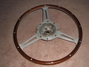
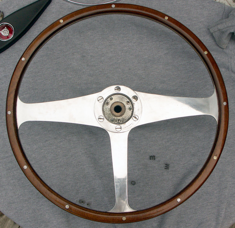
 Original Derrington 16” wheel with 8 screw mounting and 12 rivets.
The frames of the wheels were cut from Birmabright (an alloy of aluminium and magnesium with 7% magnesium and 1% manganese; also known as BS NS4, American 5251 and ISO AlMg2), and the laminated wooden rims were riveted to the frame. The laminated woodrim consisted of African Obechi wood and Mahogany. The boss (or hub) is cast from aluminium (mostly LM6) and machined to fit each particular model.
There have been many discussions over the past decades, whether this Derrington wheel was a genuine Jaguar factory option or not. Although apparently more was possible at Jaguars (including a “Bluemels wood rim steering wheel”) than one would understand from the “optional extras” 1958 list, the general opinion is that wooden steering wheels were not available as a factory option, until around 1960 when Jaguar offered a wooden steering wheel for the Mk2 (part number C.25198), but we know that this is actually not the even spaced “Derrington wheel”. Part number C.25198 is mentioned in spare parts bulletins and parts catalogues as well.
We also know that the “Derrington wheel” was rather popular in the 1950’s and was advertised in many car magazines, including those in the USA. Reference is made of the June 1960 issue of Sports Car Illustrated containing ads for the “Well Known Derrington Racing Steering Wheel”. We referred already to the two US Derrington importers, which indicates that Derrington wheels were freely available in the USA. So therefore we may assume that a (large?) number of XK’s may have received an aftermarket Derrington wheel in the 1950’s. Whether or not there was any “active support” from Jaguar USA in supplying these steering wheels remains unclear. Dealers however may have recommended these Derrington wheels themselves in order to increase sales.
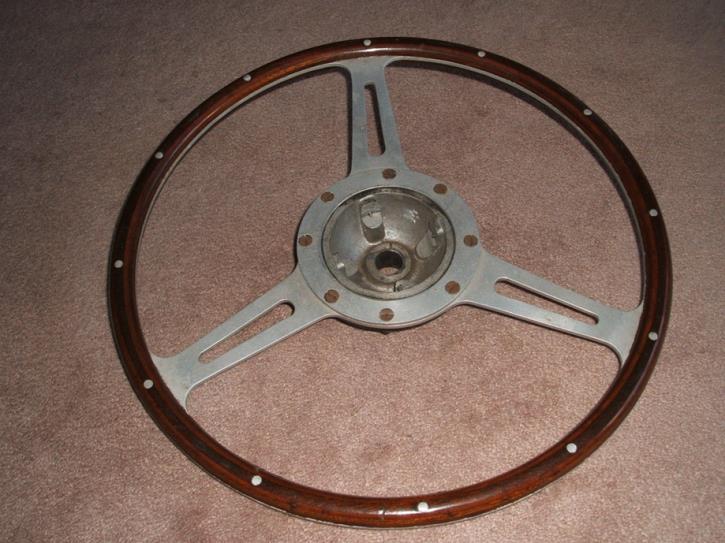
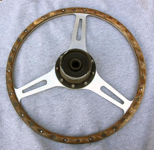
 Early Derrington wheel with 8 screw mounting.
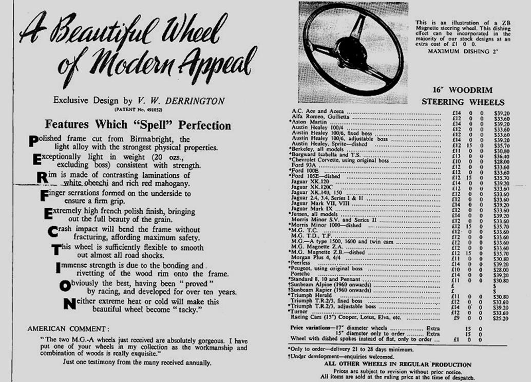
The Derrington brochure (shown below, probably dated 1960) not only lists the prices in Pound Sterling but also in US Dollar, which further supports the active marketing policy of Derrington in the USA. Also note the text in the brochure that “practically the entire output for the past few years having been exported”. This may further clarify the presence of Derrington wheels on US Jaguar XK 120, 140 and 150 in the 1950’s.
The list with (only European) car brands and types in the Derrington brochure is long and all Jaguar versions from the period 1950 to 1960 have been listed.
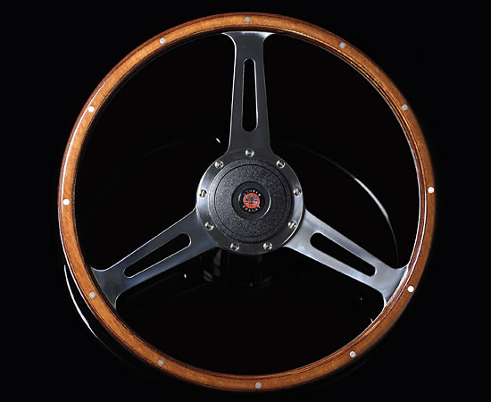
Chapter 4 Moto-Lita manufactured wheels for Derrington (~ 1960 onwards)
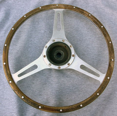
Around 1959 Moto-Lita started making steering wheels for Derrington including the famous “Derrington wheel”. Some say that Moto-Lita made wheels of that era were not of the same high quality as Derrington manufactured wheels. Moto-Lita continued the use of 12 rivets but it is unclear whether Moto-Lita was requested to continue the use of 8 bolt centre mounting or that these wheels immediately switched over to the 9 bolt centre mounting boss/hub as already made by Moto-Lita.

Above is a photo of a 1960’s Derrington wheel made by Moto-Lita. Diameter is 16 inches. It uses the Moto-Lita style hub with 9 screws. Moto-Lita still manufactures the “Derrington wheel” today and adheres to the original design although with 9 bolt centre mounting (see photo below).
 Modern Moto-Lita “Derrington wheel”
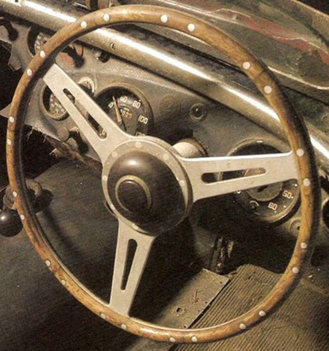
Chapter 5 Donald Healey manufactured “Derrington style” steering wheels (~ 1955 onwards)
The story goes that Donald Healey aimed at in-house production of 16” woodrim steering wheels for the Austin Healey 100 series. The designs were made by Gerry Coker and the first models were manufactured in-house. There were in fact two designs: one with drilled and one with slotted spokes. The latter has a very close resemblance to the “Derrington wheel” with even spaced spokes.
These first versions (also used on the AH 100 Le Mans cars) were made of six separate solid wood segments (not laminated) fixed to the aluminium frame by 4 rivets for each of the 6 per segments (so 24 rivets in total). They had a 9 bolt centre mounting (like Moto-Lita).
 Original AH 100 Le Mans “segmented” wheel with 9 screws and 24 rivets in “Derrington” style
The AH 100M could be delivered with the slotted spoke version as a factory option. These wheels were no longer made by Donald Healey but manufactured by the Coventry Timber Bending Co. Ltd . The Coventry Timber Bending Company was a manufacturer of “laminated and solid wood work for cars and boats”. The company had been established in 1938 by their directors: H. E. Newsum and L. G. Hains. They started activities at Swallow Road, Holbrook Lane in Coventry, but later moved to new premises about 5 miles to the east, at Bodmin Road, Walsgrave, also in Coventry. In 1954 they also produced the D-Type Jaguar steering wheel and from 1961 produced the E-Type steering wheel as well. In 1984 the company became Insolvent and was wound up.
The Coventry Timber Bending Co. manufactured “Derrington style” woodrims were made of beech and had only six rivets to fix the wood. The aluminium frame was initially riveted (not bolted) to the boss.
(See for more info: Autocar of December 2, 1962)
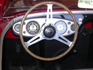 Strong resemblance, but not Derrington!
The steering wheel with drilled spokes became the standard wheel on the 100S production cars.
Around 1960 Moto-Lita began to supply “Derrington” style steering wheels to Healey, which now had 18 rivets instead of 24 for the in-house manufactured versions or instead of 6 as made by Coventry Timber Bending. These Moto-Lita steering wheels were Healey badged (or stickered).
Most likely the above photos show the later Moto-Lita made “Derrington wheels” supplied to Donald Healey with 9 screw mounting and 18 rivets! The 6 segment solid wood method has been replaced by a laminated circular construction.
Chapter 6 Jaguar Mk 2 Derrington steering wheels (different style with non-slotted spokes)
Jaguar, possibly aware of the lively interest in woodrim steering wheels, offered a special 17-inch lightweight, wood-rim steering wheel manufactured by Derrington. It seems that this version was manufactured at the explicit request of Jaguar for use to special order on Mk 2 cars.
![]()
The Birmabright spokes had been polished and the woodrim of contrasting laminations of white obeechi and rich red mahogany were clear lacquered to bring out the grain. The Jaguar wheel was priced at £12 and it takes the standard Jaguar Mk 2 half horn-ring.

“Distance Gauge” suspension XK 140 & 150
Gauge for setting front suspension and steering geometry XK 140 and 150
Introduction
A correctly set front suspension (including steering geometry of course) is an absolute must for our XKs. This not only requires a correct ground clearance (torsion bar setting), but also caster and camber values have to be within specifications. The Jaguar Workshop Manual provides a wealth of information for the XK 120 and the Mk VII models on how to adjust the above mentioned items. It also gives additional information on a special “Distance gauge” to be used for setting the (initial) torsion bar position. This distance gauge replaces the shock absorber during the set-up operation.
The “Supplement to the 120 and Mk VII Service Manuals” lists the different settings for the successor models XK 140 and 150, however without giving any information about updated “Distance Gauge” dimensions. In many cases restorers therefore simply take-over the dimensions specified for the XK 120 (or Mk VII).
As the shock absorber dimensions and mounting positions of the XK 140 and 150 are different (compared to the XK 120) it is unlikely that the XK 120 Distance Gauge can be used 1 : 1 for these successor models. In addition the various parameters (ground clearance , caster, camber) mutually affect each other. As these parameters for the XK 120 are quite different, this will be another reason why the Distance Gauge of the XK 120 might be incorrect for setting-up the XK 140 and 150. This article tries to provide additional input in order to define the dimensions for a correct Distance Gauge for the XK 140 and 150.
The two functions of the Jaguar distance gauge.
These gauges have in fact two distances to be used for different purposes:
- The longer distance is used when the torsion bars have to be placed in the reaction levers after a complete restoration.
- The shorter distance can be used for setting camber and castor and is an “alternative method” of particular use during the restoration process to have a first set-up for the steering geometry when it is impossible to use the “full weight method” as described in the Manual.
For the Mk VII the gauge provides these two distances by choosing one of the two lower holes, whereas for the XK 120 a 2½” long separate distance piece has to be placed on the long threaded top end to get the longer distance.
For the “alternative” camber and caster adjustment method, Jaguar engineers (apparently) determined the exact distance between the two shock absorber mounts for the “nominal” chassis position under full weight. This front wheel position should be identical to the position obtained according the other described method of 7⅛” ground clearance at the “lower face of the most forward parallel section of the chassis frame” under full load. And it should also match the (later) introduced measurement of 11¼” ground clearance “from underside of front cross-member”.
Jaguar XK 120 distance gauge
The Jaguar Workshop Manual provides two drawings of the distance gauges for the XK 120 and Mk VII. The distance gauge for the XK 120 is basically a rod with a threaded top end and a ring welded at the bottom.
The XK 120 gauge consists of a 5/8” (16 mm) steel rod (length about 16” or 405 mm) with a (1”OD) washer welded about 3½” from the top. Using the existing top hole of the Shock Absorber, the top of the distance gauge has a (rare) BSF 11/16” -14 threaded part over a length of 3½” from the top. This BSF thread can be replaced by a UNF 5/8”-14 thread or even an M16x2 metrical thread. At the bottom a 1¼” x ⅝” (32 x 16mm) ring is welded with a mounting hole measuring 21/32”(16.5 mm). The spacer (or distance piece) has a length of 2½” and fits over the threaded top end. An outer diameter of 1” should be sufficient for the spacer. See all other dimensions in the above drawing.
Note that the washer (positioned about 3½” from the top) should touch the lower surface of the shock absorber bracket of the chassis when setting camber and caster.
Jaguar Mk VII distance gauge
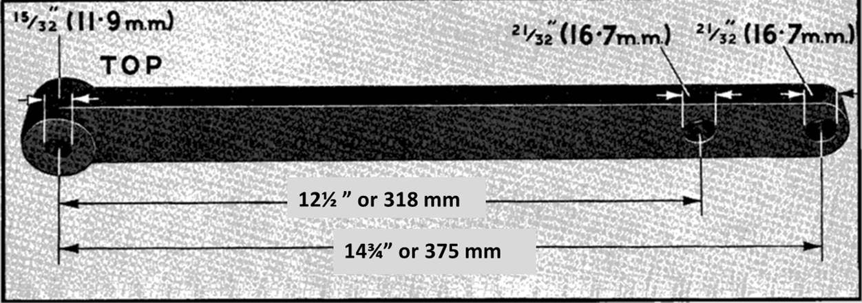
As the Mk VII has a shock absorber with two horizontal mountings, the corresponding distance gauge is different. The top of the gauge is now a steel bush with a hole that corresponds to the diameter of the upper fixation bolt (or a bit larger: 15/32” or 12.0 mm). The bottom hole measures 21/32” (16.7 mm) and is identical for both the Mk VII and the XK 120. Note that two lower holes are provided: the lower hole (distance 15⅝”) to be used for setting the torsion bars (ground clearance) and the other (distance 13⅛”) for setting up the steering geometry. The XK 120 and the Mk VII (although different in weight) use apparently the same distance for setting-up the torsion bar position. As we will see later, the actual comparable distance for the Mk VII is larger because of the different (lower) position of the upper shock absorber bolt.
Different shock absorber mountings
The top mounting of the XK 140 & 150 is clearly different: horizontal bolt fixing versus vertical threaded stud on the shock absorber for the XK 120. This will have dimensional consequences for the distance gauge. If we assume that the geometry of the shock absorber bracket welded to the chassis is (more or less) identical for the XK 120 and its successors, then we have to compensate the dimensional difference because of the way the top of the shock absorber is mounted.
Where the distance gauge for the XK 120 touches the underside of the chassis bracket, a new distance gauge for the XK 140 and 150 should be in line with the Mk VII kind of fixation (using a horizontal top bolt). The distance between the underside of the chassis bracket (where the hole is for the shock absorber) and the (centre of the) horizontal hole in the chassis bracket for the XK 140 & 150 is about ⅞” or 21 mm.
A new distance gauge for the XK 140 & 150.
The lowered position of the top bolt (⅞” or 21 mm) affects the dimensions of the new distance gauge.
- The longer gauge distance (used for initial torsion bars set-up) will be ((15⅝ – ⅞ =) 14¾” or 375 mm.
- The shorter gauge distance (used for setting camber and castor) will be (13⅜ – ⅞ =) 12½ ” or 318 mm.
Potential dimensional deviations of the gauge and their effects
We already mentioned that the XK120 and Mk VII apparently have the same gauge length for setting-up the torsion bars (ground clearance) although the required ground clearance and weight of the cars is different. However, using the aforementioned correction ((⅞” or 21 mm) the theoretical, comparable gauge distance for the XK 120 would be 14¾”or 375 mm. This implies that a lighter car requires a shorter gauge dimension for setting-up the torsion bars, which seems logical.
When the ground clearance was changed for the Mk VII (from 12¼ to 12⅝”) the distance gauge did not change. This may lead to the conclusion that the gauge length is not very critical. Remember that in fact the gauge is only used for the initial positioning of the torsion bar in the “reaction lever” and is always followed by an adjustment of the large bolt and barrel nut. Any deviation will have a limited effect as long as it still fits within the adjustment reach of the reaction lever and leaves sufficient room for adjustment.
For the steering geometry (camber and caster) the gauge is only used for setting the initial steering geometry during restoration or repair. Remember that the gauge distance here is only required to simulate the “nominal” wheel position as present under full load. We noticed a difference in gauge distance between the MK VII (333 mm) and the XK 120 (comparable: 340-21= 319 mm). This shorter gauge distance is apparently caused by two effects: a smaller king pin angle (5° for the XKs versus 8° for the MKs) and a larger caster angle for the XK 120 (initially 5° and later 3°), which again seems logical.
Finally: as the change of the castor angle for the XK 120 from 5° to 3° was no reason for Jaguar to change the distance gauge, the smaller step from 3° to 1¾° for the XK 140 & 150 may have an even smaller impact. Again we are dealing here with the initial set-up of the steering geometry, always to be followed by a professional check with special equipment.
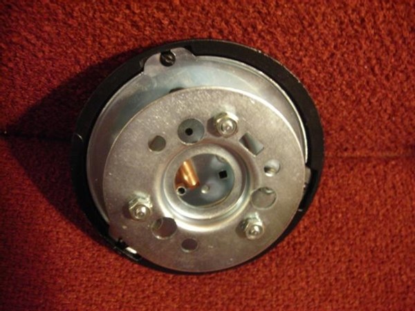
Survey of front suspension and steering geometry specifications