Category Archives: 11. Tuning
Lucas “Sports” Coils
Leave a reply
Lucas “Sports Coils”
Introduction
Many Turners had a so-called Sports Coil installed as had many other British sports cars of the 50’s and 60’s as an aftermarket accessory, in an attempt to (further) improve the car’s performance. As far as I know, none of these cars ever had a Lucas Sports Coil as a factory standard item. Further investigating the subject of “Lucas sports coils” learned that there are in fact 4 different generations of these sports coils, whereby the so-called “Red Top” version is apparently the most attractive version.
Why a “Sports Coil”?
An ignition coil is in fact a transformer with about a 100 to 1 ratio between secondary windings (consisting of 6,000 to 20,000 turns) and primary windings (normally about 300 turns). The output voltage will therefore be e.g. 100 times greater than the input voltage.
When the contact points are closed the primary winding of the coil is connected to the battery and draws an electrical current of about 4 amps. The coil core is in fact an electromagnet with a magnetic field induced by the current flowing in the primary winding. When the points open to break the contact, the primary current must stop flowing and the magnetic field in the transformer will collapse. The collapsing magnetic field forces the current to continue flowing in the same direction and that current will charge the capacitor in the distributor. This raises the capacitor voltage momentarily to about 300 Volts, at which time this high voltage stops the current. The current then reverses direction, being driven backward by the high voltage at the capacitor. The initial 300 V spike in the primary winding will induce an output in the secondary winding of e.g. 30 kV (depending on the aforementioned winding ratio).
What type of ignition coil is required for a particular engine depends on the specific requirements of that engine: aspects like C.R. (compression ratio), the chosen sparkplug gaps, etc. have an impact on the required ignition voltage for the plugs to produce an optimum spark. In addition we should keep in mind that ignition coils are strongly affected by the contact breaker, particularly at high speeds, meaning that the contact breaker should be of the right quality if the coil has to deliver top performance. On a six cylinder engine running at e.g. 4000 revolutions per minute the contact breaker has to make and break some 12000 times per minute. At each make and break a starting current (commencing at 4 Amps or so and falling away to about 1.5 Amp as speed increases) has to pass across the points without appreciable voltage drop, if the coil is to build up a maximum spark voltage during the very brief time the contacts are closed.
Standard Lucas coils normally deliver an ignition voltage of 20 to 30 kV. A “High Performance” coil and more in particular a “Sports Coil” provides an increased voltage of about 40kV or higher, because of the different relation between the number of windings of the primary and secondary windings.
Two different manufacturing methods over the years
Regarding the manufacturing method of the coil housing or “can” we see a clear split-up in the earlier “assembled” housings made of (zinc plated) steel with soldered seams and bottom versus the later aluminium cans made via a process called “cold impact extrusion”, a method also used for the manufacturing of large capacitors. Lucas introduced this process around 1950 also for the SA type of Sports Coil. Notice the “expansion” groove at the lower part of the aluminium cans, which is made to prevent the can to burst in case of an excessive overheating of the coil. Later aluminium cans no longer have the expansion groove, because other thermal protections have been built-in.
1. Lucas HS type Sports Coil from 1940s
This first generation Sports Coils coded HS was developed by Lucas in the 1940s in a 6 Volt and 12 Volt version. It started most likely as a black coated version. It may have been not available for a number of years until 1950 when it became available in a grey painted housing. We refer for this to the Lucas advertisement of April 1950 introducing the new grey coloured Sports Coil in which Lucas states: “Motorists will welcome back the Lucas Sports Coil”. A survey:
1.1 The black HS6 and HS12 coil had a brass Lucas type plate, which was fixed to the clamp with 2 screws. All HS coils are marked SW (ignition SWitch) and CB (Contact Breaker points) for the 12 Volt circuit connection.
Part numbers are unclear, but might well be identical to the successor HS coil. See 1.2.


Early Lucas HS Sports Coil with brass type plate
1.2 Early 1950 saw the introduction of the grey (brown)painted HS coil, initially with a black metal plate fixed with 2 slotted CSK screws. The housing was painted in grey-brown; this might well be Lucas “poly-chromatic” grey, a colour they used for many products like the HF1748 horns.
This coil was available in both 6V and 12V.
- Lucas HS6 Type L-0 Part # 406997
- Lucas HS12 Type L-0 Part # 406996

 Advertisement April 1950


1.3 Later (but still in the early 50s) this coil had the label glued to the coil clamp. The label was mainly aluminium coloured with a black band at the bottom. Code numbers remained unchanged.


Lucas 6 Volt Sports Coil. Model HS6, Type L-O, coil, Lucas part number 406997 with printed label.
2. The SA series Sports Coil from early 50s
In the early 1950s a second generation with a larger diameter aluminium can and different Bakelite top was introduced which was commercially named SA. This coil was still manufactured until the end of the 1970s.
Lucas SA Sports Coils can be easily recognised by their particular colour of the top part (red-brawn: these coils are also called “Red-tops”) and the special moulded Nut 422792 for the screwed connection of the HT cable to the central contact of the distributor cap; this nut differs from the one used on all other Lucas coils with a similar connection type. The diameter of Sports Coils is with 61 mm about 3 mm larger than a standard (LA or HA) coil. The clamp (or “saddle” as Lucas calls it) is also special and has part number 423947.
 Advertisement November 1957

Two versions have been made:
- Type number SA12 with part number 45058A to M for the 12 Volt version.
- Type number SA6 with part number 45065A for the 6 Volt version.
2.1 SA12 Sports Coils
Three different 12V connections have been applied by Lucas:
2.1.1 The early 12 Volt versions (coded 45058A to E) have screw posts and two nuts (2BA) for the 12 Volt wires coded 166043. These coils are marked SW (ignition SWitch) and CB (Contact Breaker points).


2.1.2 Later 12V Coil versions starting from suffix F (about 1960) were supplied with one “LUCAR” single connector (54190096) and one double connector (54190108) that could be installed on the two (2BA) studs using the existing nuts (still leaving the possibility to use this coil on older cars with eyelets). This was done because many manufacturers had meanwhile switched over to the LUCAR kind of connector for their car production.
2.1.3 Final 12V versions with suffix K to M (commencing 1968 running till 1978) had double LUCAR connectors riveted on the top, which no longer allowed the use of eyelet connectors. At the same time the marks SW and CB were replaced by + and – also because most cars had meanwhile switched from positive ground to negative ground.


2.2 Lucas SA6 Sports Coils
Below some examples of the 6V version, in this case a later version with double (riveted) Lucar connectors.


Side Note: Lucas High Energy Coils
An additional version has to be mentioned here which was not called a Sports Coil, but offered identical advantages. The High Energy Coil was offered as a period accessory in the 1960s. This coil has a die casted Aluminium housing (heat sink) and a unique bracket with the Lucas logo in blue. Note the top that is identical to the SA Sports Coil with a screw-in type high tension connector and screw posts for the primary terminals.

3. PA series “High Power” Sports Coils from late 50s
Introduced in late 50’s or early 60’s, this type of sports coil used the standard housing of the HA type High Performance Coils and not the (larger) housing of the SA type of sports coils. In addition it no longer carried the HT lead connection by means of a “moulded nut and split washer” but changed over to a “screw-in” connection for the HT cable to the distributor cap. The PA series were part of the Lucas range, not replacing but in addition to the SA series over the period 1960 – 1980.
Lucas issued a leaflet “Instructions for fitting sports ignition coils models PA6 (6 volt) and PA12 (12 volt) export only, SA6 (6 volt) and SA12 (12 volt) home market” which might indicate the relation between the two product ranges. The reason for this might be that the non-UK (read “non-Lucas”) car industry used HT cables connected by means of a system whereby the (core of the) cable was screwed into a thin threaded stud. Due to the dominant position of Lucas in the UK it could continue the SA series with the “moulded nut and split washer” connection.
- Sports Coil fluid cooled 12V PA12 45118
- Sports Coil fluid cooled 6V PA6 45119
 SA6 Sports Coil Lucas 45119

4. The SP type Super Energy Sports Coil from late 70s
A fourth generation Sports coil (also known as the Gold Sports coil) was introduced around 1978 with the type code SP. The commercial code was:
- DLB 105 for the standard Super Energy Sports Coil
- DLB 110 for the “ballasted” version of the same coil (50% lower resistance of the primary windings)
There are (at least) three different versions of this coil.
4.1 The SP12 Super Energy Sports Coil with Silver label (late 70s to late 80s)
Early coils had a white top with double LUCAR connections riveted to the top. The SP12 coil had Lucas part number 45288A (at least initially) and had a silver label with “12V Super Energy Sports Coil” printed. Note that these early SP12 versions had an “expansion” rim at the lower end of the housing, in line with the housing of the SA series.
 Earlier SP12 45288A 1980

4.2 The SP12 Super Energy Sports Coil with Black label (late 1980s)
A later version of the 1980s (now also named DLB105-B) with part number 45341A had a white top, but now with a black label positioned on the clamp and no longer on the housing above the clamp. The abbreviation B.Y.S. (manufacturer code?) was added in the numbers stamped on the bottom of the coil. These coils went back to the screwed Lucas low volt terminals which allowed to use this coil also for the classic eyelet connections. These coils have most likely been manufactured from late 1980s till about 1996 when Lucas was sold to a US company.


B.Y.S SP12 45341A from 1987
4.3 The SP12 Super Energy Sports Coil with Green label (since September 2004)
Following the return of “Lucas Electrical” in the UK market the DLB105 / SP12 “Gold” sports coil was continued, however with a green Lucas label on the coil clamp.

Probably the most recent version is made with a black top and with removable “Lucar” connectors, opening the possibility to have eyelet connections as well. Also note that the clamp has now “open” mounting holes.

Checking a Sports Coil
Start by checking the resistance of the primary winding. Whereas about 3.2 ohms is standard for an un-ballasted ignition system, about 1.5 Ω is standard for the ballasted ignition system, but the primary coil resistance of a Sports Coil should be 2.5 to 2.7 Ω which is somewhat lower than that of standard coils. The secondary coil windings have a much higher resistance.
|
Coil type |
Primary resistance Ω |
Secondary resistanceΩ |
|
Standard Coil Q-12 |
4.39 |
5190 |
|
Standard Coil LA-12 |
3.3 |
8250 |
|
Sports Coil SA-12 |
2.6 |
10050 |
|
Sports Coil SP-12 |
3.2 |
8660 |
Wire wheels: worn hub and wheel splines
Wire wheels on Turners
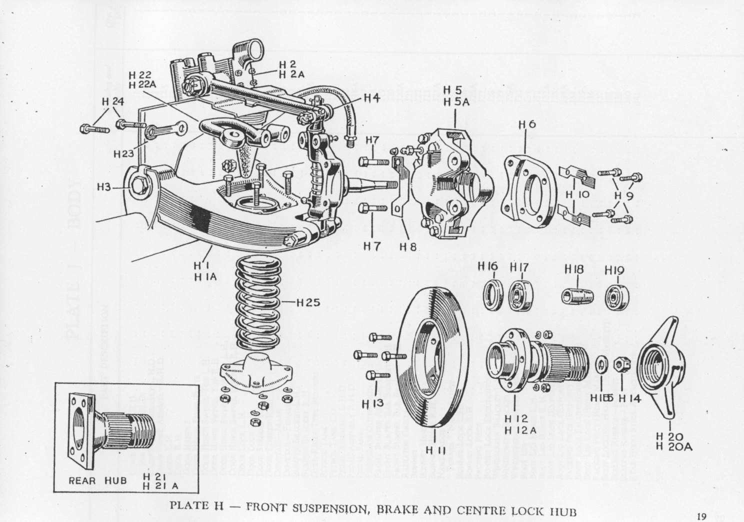
Many Turners received wire wheels either as a standard factory option or as a later “aftermarket” change. This was (always?) combined with a Girling Type 10 disc brake conversion at the front and required the use of special splined hubs on both axles. See page 19 of the Turner Parts Catalogue below. Turners used both 13 and 15” wire wheels.

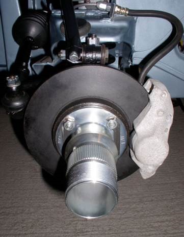 Special splined hubs for Girling Type 10
Wire wheel fixation
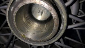
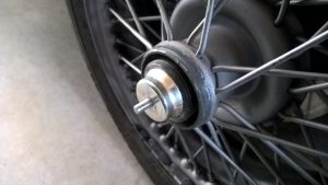
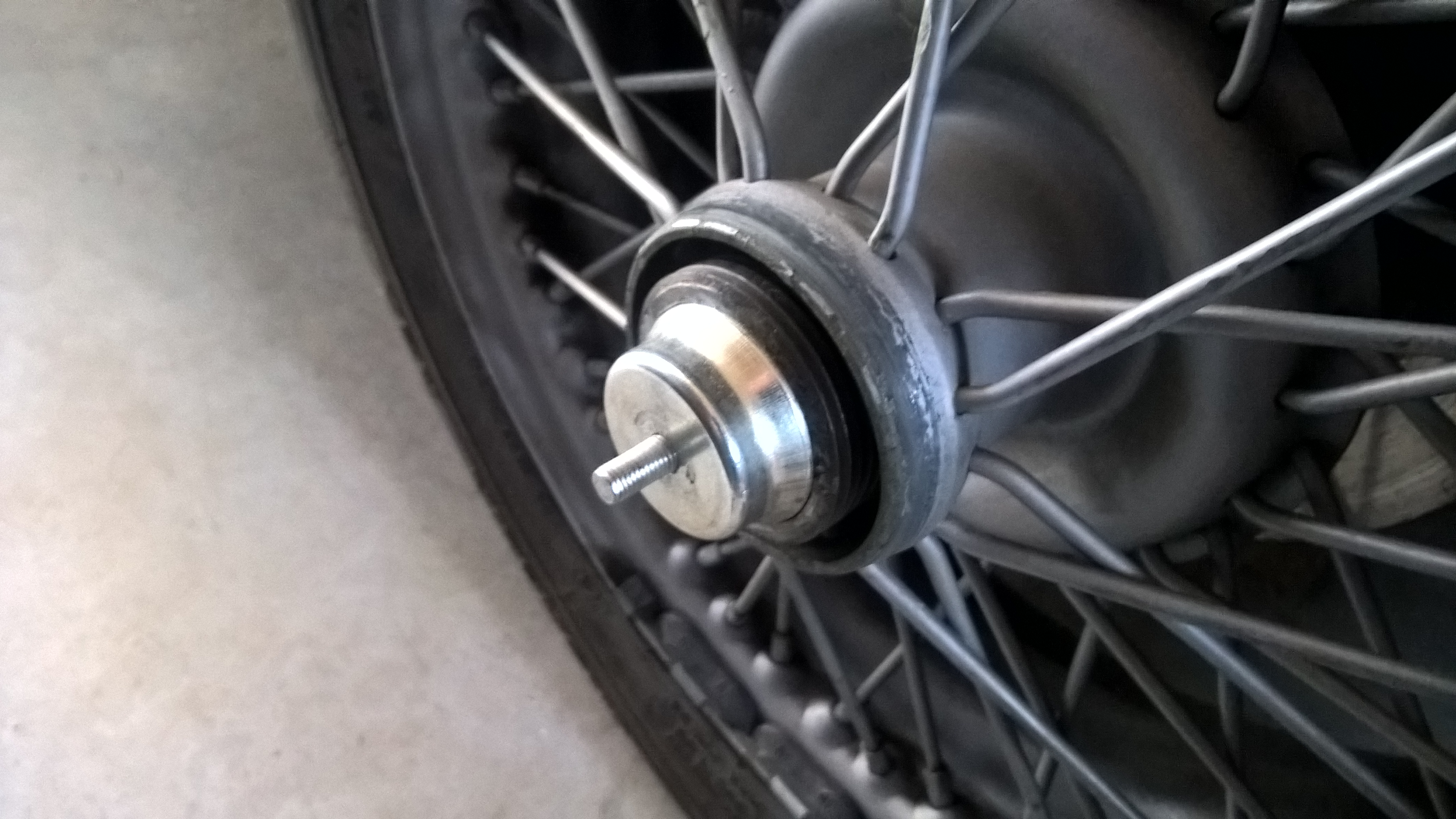
Detachable wire wheels have a different way of fixation compared to normal disc wheels, as they are mechanically “connected” to the axle hubs in two ways:
1. In a rotational direction by means of driving splines (serrations) on the (stub) axle hubs and driven splines on the inner wheel centre.
2. In an axial way by means of a (threaded) locking nut preventing the wheel to become disconnected from the threaded axle hub.
This article will not tackle the subject of which wire wheel types have been applied over the years; see the appropriate literature for that. We do want, however, to emphasise the potential danger of wire wheel fixation systems after many years of use (and abuse) to the point where they become even highly dangerous! In addition, some guidance is provided in checking whether a wire wheel can still be safely fixed to the car.
![clip_image002[4]](http://www.bobine.nl/turner/wp-content/uploads/2014/06/clip_image0024.gif "clip_image002[4]")
A – Locking thread on hub (left or right hand thread).
B – Driving splines on hub.
E – Driven splines of wheel centre.
Rudge-Whitworth fixation
The system of detachable and interchangeable wire wheels has been initially designed by John Pugh around 1910 but is better known under the (company) name of Rudge-Whitworth.
The resulting standardisation of detachable wire wheel fixations in Europe dates back to the 1920’s. The basis for this standard was the load to be carried per wheel and the required bearing diameter for that, resulting in a certain cross section for the hub. Note that the wheel type designation in the standard are basically structured around the (metrical!) dimensions of (then available) wheel bearings.
![clip_image002[6]](http://www.bobine.nl/turner/wp-content/uploads/2014/06/clip_image0026_thumb.gif "clip_image002[6]") Advertisement 1912
Advertisement 1912
![clip_image002[6]](http://www.bobine.nl/turner/wp-content/uploads/2014/06/clip_image0026.gif "clip_image002[6]")
Wear on splines and thread
Over the years the thread of the locking nut and the hub itself may wear but (even more important) the splines on the hub and in the wire wheel centre may wear to the extent that the construction eventually becomes unsafe. Therefore it is wise to regularly check them and more in particular during any XK restoration as the condition and history of axle hubs and wheels are unknown.
Four dimensions are of importance here and have to be checked:
1. The maximum allowed inner diameter of the thread of the lock nut
2. The minimum allowed outer diameter of the thread on the wheel hub
3. The minimum allowed outer diameter of the splined hub
4. The maximum allowed inner diameter of the inner wheel centre splines
Please note that wear of splines and thread is accelerated if the wheel is not fitted tightly!
Cross-section of Rudge-Whitworth hubs
The principle wheel type designation according the Rudge-Whitworth standard refers to the maximum size of an outer wheel bearing (in millimetre) which can be used with that hub. The actual hub diameter is measured across the outside of the splines on the axle hubs (not the wheel splines).
|
Wheel Type |
Actual hub diameter |
Number of splines |
Spline length Long Hub |
|
35 |
52 |
62 |
56 |
|
42 |
62.5 |
75 |
62 |
|
52 |
73 |
88 |
62 |
|
62 |
82.5 |
100 |
78 |
|
72 |
92 |
112 |
84 |
|
80 |
102 |
124 |
87 |
|
90 |
111.5 |
136 |
94 |
|
100 |
123 |
150 |
97 |
|
120 |
137 |
168 |
101 |
Two wire wheel types are normally used on British sports cars: type 42 and 52. Turner opted for the smaller Type 42 wire wheels also due to the rather limited weight of their sports cars. The (course) thread of wire wheels has a top angle of 60° and a pitch of 8 TPI (or 3.2 mm) although some earlier versions may have used 12 TPI (or 2.1 mm).
 Alexander-Turner with 15″ wire wheels

Dimensional requirements for Type 42 wire wheels: worn or still OK?
Further to the aforementioned important testing criteria, the survey below gives specific information regarding when a splined hub, wire wheel or locking nut should be replaced.
- The locking nut should be checked for wear on the (internal) thread. If a cylinder with an outside diameter of 2.211” or 56.2 mm should fit in the locking nut, wear has progressed to the extent that the locking nut has to be replaced.
- If a tube with an internal diameter of 2.291” or 58.2 mm fits over the thread of the axle hub, wear has progressed to the extent the complete hub has to be replaced.
- If a tube with an internal diameter of 2.424” or 61.6 mm fits over the splines of the axle hub, the complete hub has to be replaced.
- If a cylinder with an outer diameter of 2.374” or 60.3 mm fits in the internally splined wheel centre, the complete wire wheel has to be replaced.
Note that the above dimensional requirements are no more than minimum requirements! As an example: wire wheel constructions fulfilling the above requirements have a remaining overlapping contact height of the splines of no more than (61.6 – 60.3 =) 1.3 mm. Although the contact surface is of course larger due to the 60° V angle of the spline and the length of the spline (here 37 mm), in comparison a new type 42 spline has a contact height of 62.3 – 59.6 = 2.7 mm, meaning that the (safety?) margin has been more than halved.
So don’t use any hubs or wheels with spline dimensions below the above given minimum requirements!
Stub axle repair Turner 950
After more than 60 years of (intensive) use the stub axles of Turner 950’s may have suffered to the extend that e.g. bearings have too much play on the axle and replacement is required. Especially those having the special Girling Type 10 disc brakes mounted, may be a candidate for stub axle replacement.

New complete stub axle/kingpin forgings (BMC part number BTA 744 and 745) are difficult (impossible) to find and used replacements may have suffered even more than the old ones you are about to replace.
Installing a new stub axle may be the solution but requires certain skills and equipment but can be done. The attached drawing could offer some guidance for this replacement: any well equipped shop could make this axle. The old axle has to be machined from the upright and the diameter and length of the machined hole and new stub axle should be matched to secure a good press-fit.
New bearings SKF 7205 (Ø 25,0 x 52,0 x 15 mm) and SKF 7303 (Ø 17,0 x 47,0 x 14 mm) should be installed and the bearing spacer (88G321) between the 2 bearings checked for correct dimensions as the correct bearing play is determined by the length of this part in combination with the castle nut adjustment. Use new washers (2A 4003) and castle nuts (51K 328).

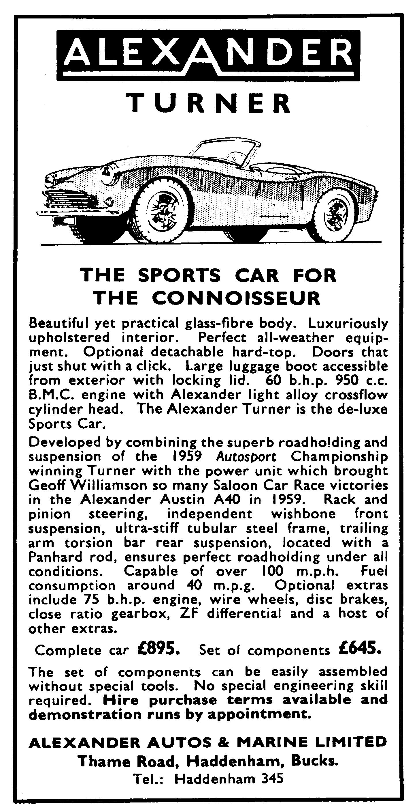
Turner-Alexander or Alexander-Turner?
Turner-Alexander or Alexander-Turner?
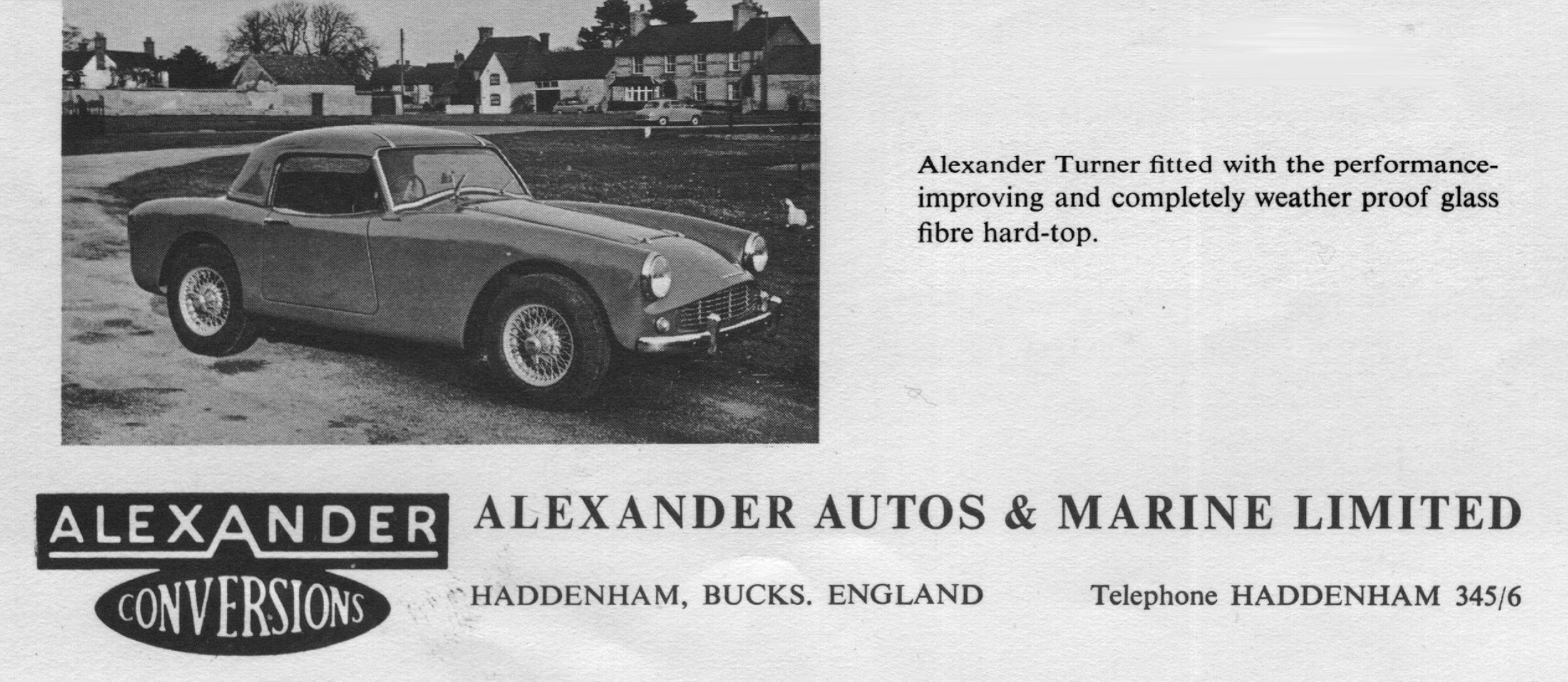
It had become a kind of tradition for Alexander Engineering of Haddenham (Buckinghamshire) to present their latest developments in the form of a special testday, giving the press ample opportunity to judge the qualities of the various cars that were put at their disposal. The company, headed by Michael Christie, had built up quite a reputation in making engine and suspension conversions for practically every available car in the late fifties and early sixties. In particular, their achievements in upgrading the BMC-A engine, found in so many cars in that period, established their name among the long list of tuning companies like Derringtons, Raymond Mays, Aquaplane, Arden, Speedwell and Downton, to name but a few.
It was a surprise for the motoring press when Michael Christie announced in November 1959, during their yearly autumn presentation, organised this time in the Weston Manor Hotel in Bicester, that Alexander had made an agreement with Turner of Wolverhampton and would distribute the new Turner 950 Sports (later to be known as the Mark 1). Delivery of the new car would commence after Christmas and many products from the vast Alexander range, including engine, suspension, brakes and interior, would be available for the Turner-Alexander right from the start.

It is interesting to note that Alexander went their own way with respect to component sourcing. Apart from the obvious choice of their light alloy cross-flow cylinder head, the long list of “Approved optional equipment” offered no less than 20 different items, amongst which a Lockheed servo in combination with the Girling disc-brake system, specially developed for the Healey factory (Sebring) Sprites and the Turner 950 Sports.
The cross-flow cylinder head (CR 9.4 to 1) delivered in combination with twin SU H2 carburettors about 60 bhp at 6000 rpm, compared to the 43 bhp at 5000 rpm (CR 8.3 to 1 and twin SU H1) of the Turner in standard form. The Autocar, reporting about the new Turner-Alexander on 4th December 1959, mentioned that a maximum output of 80 bhp was claimed if combined with high compression pistons and a road-racing camshaft. They also mentioned that a new company (Alexander Autos & Marine Limited) would market the car, using conversion parts supplied by Alexander Engineering.
In the January 1960 issue, Motor Sport complimented the car they tested during the November presentation in Bicester. Especially the body finish and weather protection impressed them. Funnily enough the engine of the Alexander-Turner (note the different order of the two brands as compared to the Autocar story) was less impressive, being described as “a rather tired hack engine which did not help to show the car up in a good light”. However, they promised to perform one of their “normal rigorous tests” on the car in the following months, a promise they did not keep.
Two road tests, however, were published as a result of the active marketing policy of Alexander. The first one was in Sports Car and Lotus Owner in March 1960, followed by another in The Motor of August 10 of the same year: quite some coverage for such a small company.
David Phipps (Sports Car and Lotus Owner) is full of compliments, referring to the Alexander-Turner (333 KPP) as “a 948 cc car with the performance of the 1½-litre MGA”. Performance and roadholding are described as “very good”. The Alexander-Turner, of course, had much in common with the Turner 950 Sports, but Alexander offered the double trailing arms to locate the rear axle as a standard, a construction that Turner recommended for the more powerful tuned versions and the Turner-Climax Sports with the Coventry Climax FWA engine. The standard 15 inch wheels were combined with a somewhat lower geared final drive (4.875 compared to 4.55 for the standard Turner). Acceleration figures were impressive for a 950 cc car: 0 – 60 mph in 13.6 seconds; and the recorded top speed was over 90 mph! David Phipps reported that Alexander had started experimenting with 13 inch wheels to further improve road handling.
Another interesting observation is that Alexander were apparently still experimenting with the inlet manifold, showing a large balance pipe between the four inlet tubes (yes four, no Siamese port on the cross-flow Alexander head!) in March 1960, that had been reduced to a thin balance pipe by mid-1960 in its final form..
The Alexander-Turner tested by The Motor (500 NKX) had received the thirteen inch wheels as already indicated in March. Other changes included twin SU H4 and the final drive back to 4.55. The acceleration from 0 to 60 mph remained unchanged at 13.6 sec, while maximum speed went up to over 95 mph! The Motor Road Test No. 28/60 is very accurate in this respect, even down to the 5% misreading of the speedometer. The Motor came to the conclusion that this car was perhaps too highly tuned for the majority of sports car buyers, but what remained was a feeling of “enjoyment of a comfortable, lively and exceptionally controllable little car”.
Although Turner’s are often referred to as “kit cars”, in fact only a part of the total factory output was supplied as a kit, especially for the home-market. A considerable part of the production went overseas and these were all completely assembled in Wolverhampton. Alexander delivered their “kit” on request, adding all the Alexander “goodies” the customer had asked for, but also undertook the conversion and tuning of factory-built Turners.
In the Sporting Motorist of January 1961, proud owner Ashley Clarke describes in detail how he built an Alexander-Turner, supplied as a kit, in just a hundred hours. It offers an excellent insight into what building a Turner meant: trying to save Purchase Tax (which had been lowered in April 1959 from 60 to 50% of the basic price, still equalling between £250 and £350 in the case of the Turner 950 or Turner Climax) meant investing a lot of spare time.
Alexander remained official Turner distributor till the mid-sixties. Turner had a habit of changing agents rather frequently (or was it the other way round?). In the period from 1955 to the end of the decade, Bob Gerard, combining racing and selling Turner Sports Cars, was their East Midlands Distributor, while Field’s Garage in Chichester had taken responsibility for South East England. In the early sixties, apart from Alexander Autos and Marine Ltd. covering the South, Gordon Unsworth of Motorway Sales in Derby became Turner’s new agent, taking over from Bob Gerard.
Up to 1964, things looked rather bright for Turner, still with amazing racing success, Turner’s keeping lap records at every UK circuit and with exports across the Atlantic and to South Africa continuing to be their main source of income. But Jack Turner went into voluntary liquidation in early 1966 following Jack’s illness and a number of other mishaps.
Alexander Engineering Co. Ltd. still exists almost forty years later at the time of writing. Now headed by son Timothy Christie, they are an active as well as important supplier to the automotive industry, in particular in the area of accessories and lighting equipment. They still occupy their historic premises at Thame Road in Haddenham.
BK 1999
Alexander-Turner Brake Servo
Alexander-Turner Brake Servo
The Turner-Alexander had a number of optional extras in 1959 and 1960, like Girling front disc brakes and a Lockheed brake vacuum servo: indeed an intriguing combination! Girling front disc brakes were £25 whereas for the Lockheed brake vacuum servo another £20 had to be paid.
The Girling Type 10 disc brakes are described under the Category “Brakes” and “Tuning” on this website. This document describes the Lockheed brake servo.
Lockheed 5½” Brake Servo
At the end of the 50’s Lockheed had already a number of brake servo system in their programme, but most of them based on a vacuum piston moving in a cylinder with leather or rubber piston rings. A new generation using a rubber diaphragm was introduced allowing for a more compact design, making the vacuum servo piston no longer required.
Thus the new 5½” Brake Servo version was chosen by Alexander to assist the new Girling Type 10 disc brakes that required a (much) higher pedal pressure.

There were various versions with different slave cylinder sizes: 5/8”, 11/16”and 7/8” diameter all sharing the same vacuum housing. Most probably Alexander had chosen for Lockheed servo type number 112753 with a 7/8” slave cylinder, which was an “Installation Kit” without specific applications mentioned. There was an alternative “Installation Kit” which had a later Lockheed type number 4257-064, having the same slave cylinder dimensions but a different Air Control Valve housing.

A similar Lockheed servo was later introduced on the Mk1 Cooper S models (1963 onwards). All Mini Cooper S Mk 1 models came with this Lockheed type 5½” vacuum-operated brake servo unit as standard, fitted to the RH wing valence of the engine compartment. Both end covers (dishes) and the collar of the brake servo were cadmium plated, giving an unpolished bluish-white finish. The brake servo slave cylinder should be finished in matt black.
The Cooper S brake servo looks similar to the original Alexander-Turner versions and could be used.
Spare Parts
The servo Lockheed Nº 112753 required a Major Repair Kit Nº SSB.1003 and an Air Control Kit Nº SSB.1004.
The servo Lockheed Nº 4257-064 required also Major Repair Kit Nº SSB.1003 but a different Air Control Kit Nº SSB.1002.
The Cooper S servo required a Major Repair Kit Nº SSB.1036 and an Air Control Kit Nº SSB.1002.

Lockheed Air Control Kit Nº SSB.1004

Lockheed SSB.1002 Air Control Valve kit

Lockheed SSB.1036 Repair kit. The repair kit SSB.1003 will look similar.
Thermostat Housings BMC-A
Thermostat Housings BMC-A
The Thermostat housing of the BMC 950 engine of Turners sometimes corrode to the extent that they start leaking and have to be replaced. Finding a replacement is no problem: see the survey below. All versions use the same Gasket GTG 101.
Housings from AH Sprite/MG Midget (vertical flow radiators)
- 948 cc AEA306
- 1098 12G243
- 1275 12G1445
Housings from AH Sprite/MG Midget (later cross flow radiators)
- 1275 12G1902


Thermostat housing early sprite (AEA306) Thermostat housing cross flow radiator (12G1902)
Even those from the Austin/Morris Mini (incl. Cooper) may fit:
- 998cc 12G103
 Thermostat housing Mini 998 (12G103)

![]() Accessories
Accessories
When the thermostat is removed (e.g. racing engines) a blanking sleeve is required to secure a good coolant flow.
 Thermostat blanking sleeve 11G176

13” Moto-Lita Mk III in Turner
Moto-Lita Mk III Steering wheel flat 13” wood rim (early version)
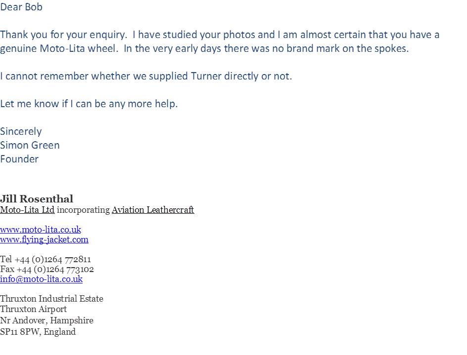
My Alexander-Turner 950 came with a 13” wooden steering wheel. It turned out to be a very early genuine 13” Moto-Lita Mark III as confirmed by Mr Simon Green, founder of Moto-Lita . A copy of his email is shown below.
 Wheel
Wheel

 Boss
Boss

History
Moto-Lita are about the only survivor from the 1960’s. Early steering wheels supplied by Moto-Lita have no markings. However, in the late 80’s and early 90’s, as demand increased for these steering wheels Moto-Lita began to mark them with “Moto-Lita” on the back side of the steering wheel. Usually on the left ( horizontal ) spoke as viewed from the rear.
The Mark III Wood Rim steering wheels, were the very first Moto-Lita range of wheels to be manufactured at our Surrey factory in 1957. Wheels from this range were supplied to many of the Classic British car makers such as A.C, Cooper, Healey, Jensen, MG Car Company and TVR to name a few.
Original brochure early 60’s


![]()
![]()
Derrington steering wheel hub for flat wood rim wheel
Looks identical to the Moto-Lita boss. Is it?


New Moto-Lita Mk III Steering wheel dished 13” wood rim

Girling Front Disc Brakes on Turners.
 Period Girling advertisement mentioning Turner next to all the “big guys”

In 1959 the Turner 950 BMC-A and Coventry Climax got disc brakes as a factory option. This was the recently introduced (second generation) Girling Type 10 disc brake system. Girling (part of the Lucas group) began experimenting with disc brakes on race cars in 1952. An early generation Girling Type A solid caliper 11″ disc brakes had been used on the Triumph TR3 from 1956. Turner (as a small company) was one of the earlier adopters (1959) installing disc brakes on their sports cars. It required the use of special mounting brackets to mount the callipers to otherwise standard front hubs.


Girling Type 10 Callipers (Turner H5 and H5A) and Mounting Brackets (Turner H6) on my Alexander-Turner 950
 Complete Girling front brake system on Turner 950
Girling Type 10 Disc Brakes
Applications:
- Austin Healey Sprite Factory Conversions (Sebring Sprite) from 1959 onwards
- Berkeley Bandit from 1960 onwards
- Turner 950 BMC-A (optional) and Coventry Climax from 1959 onwards
Girling part no Description (and Turner reference number)
- 64032502 Calliper assembly LH (Turner H5)
- 64032503 Calliper assembly RH (Turner H5A)
- 64325873 Piston
- 64325183 Calliper mounting bracket (Turner H6 2x)
- 64325186 Disc (Turner H11)
- 64325027 (GDB 509 – DS 5S) Pad
- 64325418 (GDB524) Pad (alternative)
- 64325022 Pad Retaining Pin
- 64325009 Retaining Pin Clip
- SP2507 Service kit callipers
 Exploded view of Type 12 calliper; Type 10 is similar


Pistons 64325873 tend to corrode after many years of use (moist in brake fluid!) and are hard to find. I had new ones made in Cr Ni steel according above left drawing. Also the pins 64325022 have a hard life and making new ones is not so difficult (see 2nd drawing). These items are both used in Type 10 and Type 12 systems.
Girling Type 12 Disc Brakes
Applications:
- Triumph Herald Oct 1961 onwards
- Triumph Vitesse “6” 1962 onwards
- Turner GT and Coventry Climax 1220 from 1962 onwards
Girling part no Description
- 64032604 Calliper assembly LH
- 64032605 Calliper assembly RH
- Non-Girling part Disc
- 64325708 Pad
- SP2529 Service kit callipers
Discs dimensions for Turner Sports 950 BMC-A and Coventry Climax from 1960 onwards
Original Girling code was 64325186 (for Turner H11)
| Dimensions |
Metric |
Inch |
| Outer diameter |
Ø 217 |
8 9/16” |
| Overall width |
23.5 |
15/16“ |
| Disc thickness |
9.6 |
3/8” |
| Minimum allowed thickness |
8.6 |
|
| Centre hole diameter |
Ø 63.5 |
2½ |
| Bolt pitch circle |
Ø 87.3 |
3 7/16 |
| Bolt hole (4x) |
Ø 9.6 |
3/8” |
These Girling discs are no longer available. Whether Girling also provided the hubs is still point of investigation. The origin (and supplier) of the Turner hub is unclear.
Other potential Turner suppliers had different dimensions: Austin-Healey Sprite has a bolt pitch circle of Ø 81.0. Triumph (Herald, Spitfire) had indeed a value of Ø 86.6 mm, but the disc is otherwise different (overall width and diameter) and cannot be used.
The Ford Escort Mk1 1300 GT disc comes very close with a bolt pitch circle of Ø 86.4 although this is a non-Girling system.
Front Brake Pads for Turner 950 BMC-A and Coventry Climax from 1960 onwards
Original Girling part number 64325418 or GDB524(no longer available). Dimensions: 62 x 43 x 15 mm. Same part number is also used as rear brake pads on Lotus cars:
- Elan 1.5 (1962-1965)
- Elan 1.6 (1966–1974)
- Elan 2+2 1.6 (1967-1971)
- Elan 130/4 (1971-1974)
- Elan 130/6 (1972-1975)
- Elite 1.5 (1958-1964)
- Elite Mk II (1961 on)
Corresponding Lotus part numbers:
- 036J6066 (non-servo version)
- 036J6064 (servo version)
Other brands that supply this product:
- NU-TEXA DP46
- EBC DP145 complete axle set
- Bendix B300119
- Ferodo FER DA3 FF 517

 Bendix B300119

 Ferodo DA3 FF 517
Modification of Ford Escort Mk1 1300 GT Front Brake Discs
Ford Escort Mk1 GT discs can be made to fit with slight machining. Original Ford part number: (Ford GB) 3026E1123C/68AB1125AA; (Ford D) 1450669. This disc is used on Ford Escort Mk1 1300 GT (from 8/1969 till 11/1974). For dimensions and tolerances see Brembo drawing (below).
Other manufacturers that supply this disc type:
- Brembo 08164310
- Ferodo DDF 009
- EBC D080
- SAP motor parts BDC 1018
- Autonational BDC 0079
![]() Comparison of dimensions Turner versus Ford disc:
Comparison of dimensions Turner versus Ford disc:
| Dimensions |
Turner |
Ford |
| Outer diameter |
Ø 217 |
Ø 218.6 |
| Overall width |
23.5 |
23.3 |
| Disc thickness |
9.6 |
9.65 |
| Minimum allowed thickness |
8.6 |
8.6 |
| Centre hole diameter |
Ø 63.5 |
Ø 63.1 |
| Bolt pitch circle |
Ø 87.3 |
Ø 86.4 |
| Bolt hole (4x) |
Ø 9.6 |
Ø 9.9 |
The Ford Escort Mk1 GT disc has a different pitch circle (about 1 mm smaller) which does not allow a direct exchange. Three possible solutions:
- New holes have to be drilled at the correct pitch circle Ø 87.3 mm.
- The holes in the Ford disc have to be enlarged from Ø 9.9 to Ø 10.5 mm.
- The holes in both hub and disc to be enlarged to Ø 10.0 +0.05 mm.

Girling Type 10 on Sprite Factory Conversions (Sebring Sprite)
The Donald Healey Motor Company supplied conversion parts (as per Sebring Sprite) including wire wheels and disc brakes with special Ø 8½” (216 mm) front discs and Girling callipers (1958-1961).

 Original front splined hubs and a pair of new replacements (as reference for Turner H12 and H12A).
 Dust caps (foreground) are larger than standard B.M.C. items. Caps are tapped home inside hub.


 Original Girling ‘Type 10’ brake callipers, including pads and stub axle mounting brackets.

 Stub axle mounting brackets for the Girling Type 10 set-up.
 Original Girling ‘Type 10’ calliper
Alexander Front Anti-roll bar
Description of the ALEXANDER Front Anti-roll torsion bar for Turner
The Alexander Anti-roll bar system consists of a standard 11/16“ (17.5 mm) torsion bar and an additional ¾” (19.0 mm) rod for increased stiffness.
![clip_image002[4]](http://www.bobine.nl/turner/wp-content/uploads/2013/05/clip_image0024.jpg "clip_image002[4]") Original Alexander folder
Original Alexander folder
The standard bar connects LH + RH lower wishbone (via rubber mountings) with the front end of the chassis (rubber mounted distance brackets). The ALEXANDER Anti-roll bar was available as an option for cars like the A35, A40, Sprite/Midget and some larger BMC-B engined cars from the early 60’s. Also Turner offered an Anti-roll bar as an option.
The additional stiffening bar is connected via four brackets, securing the ¾” bar to the 11/16” bar and is probably a later addition. The four brackets are branded: DEE JAY RACING.
Parts list:
- Torsion bar Ø 11/16” 1 pc
- Suspension bracket (bar to chassis) 2 pcs
- Rubber bush for 2. Ø 5/8” inner x Ø 1 1/8”outer x ¾” 4 pcs
- Pressure plates for 3. 4 pcs
- Bolt for 4. 3/16” BSF x 2” 4 pcs
- Self-locking nut for 5. 3/16” BSF 4 pcs
- Bolt (susp. bracket to chassis) 3/8” UNF (5/8”) x 4” 2 pcs
- Self-locking nut 3/8” UNF 2 pcs
- Washer 5/8” large (3D) 2 pcs
- Bolt (bar to lower wishbone) 5/16” UNF (3/8”) x 3” 2 pcs
- Self-locking nut 5/16” UNF 2 pcs
- Rubber bush for 10. Ø 3/8” inner x Ø 1 1/8”outer x ¾” 4 pcs
- Dish for 12. 4 pcs
- Washer (wishbone side) 5/16” large 2 pcs

Additional Stiffening Bar:
15. Torsion bar Ø ¾” 1 pc
16. Connecting bracket (short, centre) 2 sets
17. Connecting bracket (long, side) 2 sets
18. Bolt (for 16 + 17) ¼” UNF x 13/4” 8 pcs
19. Self-locking Nut ¼” UNF 8 pcs
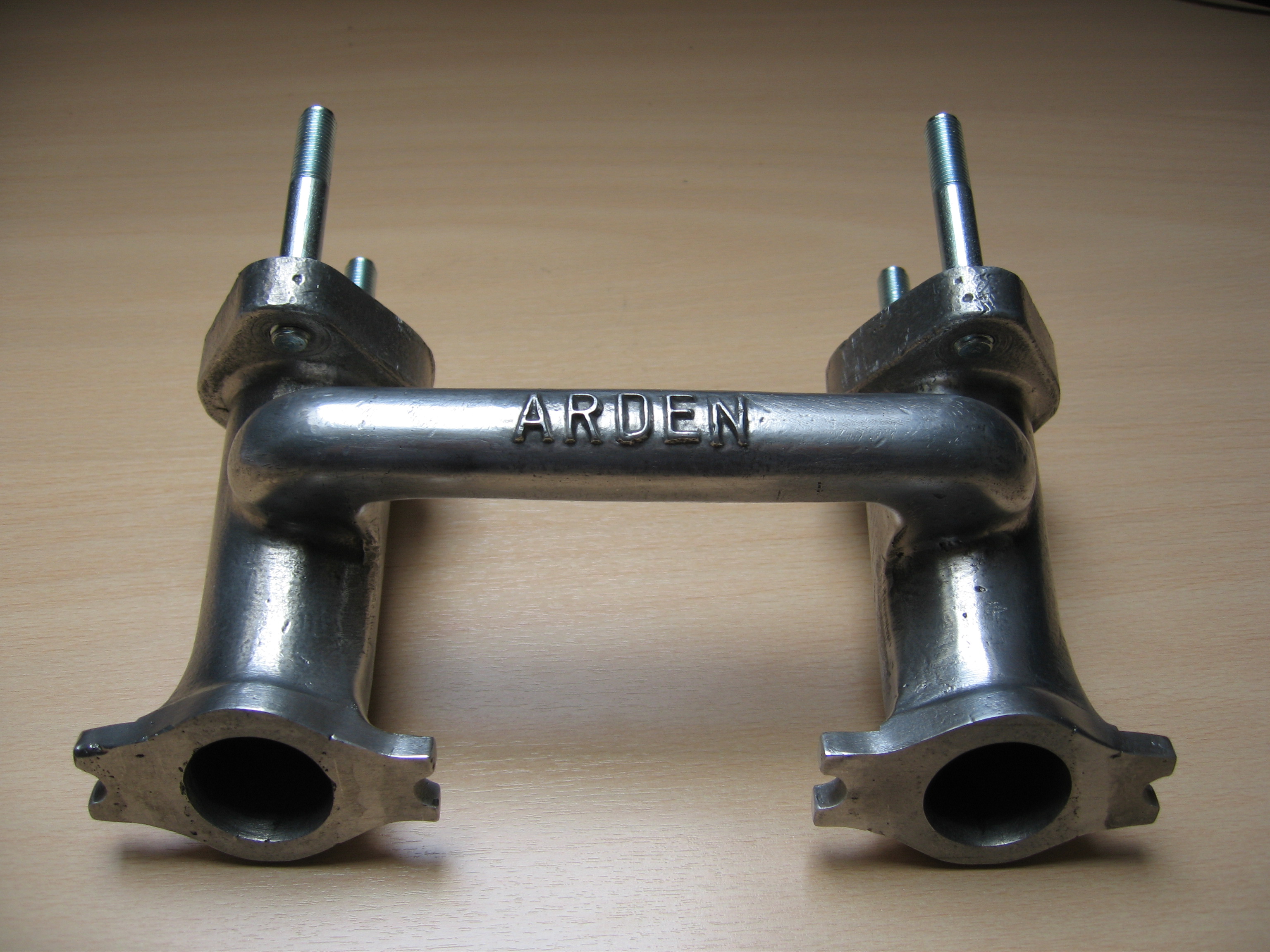
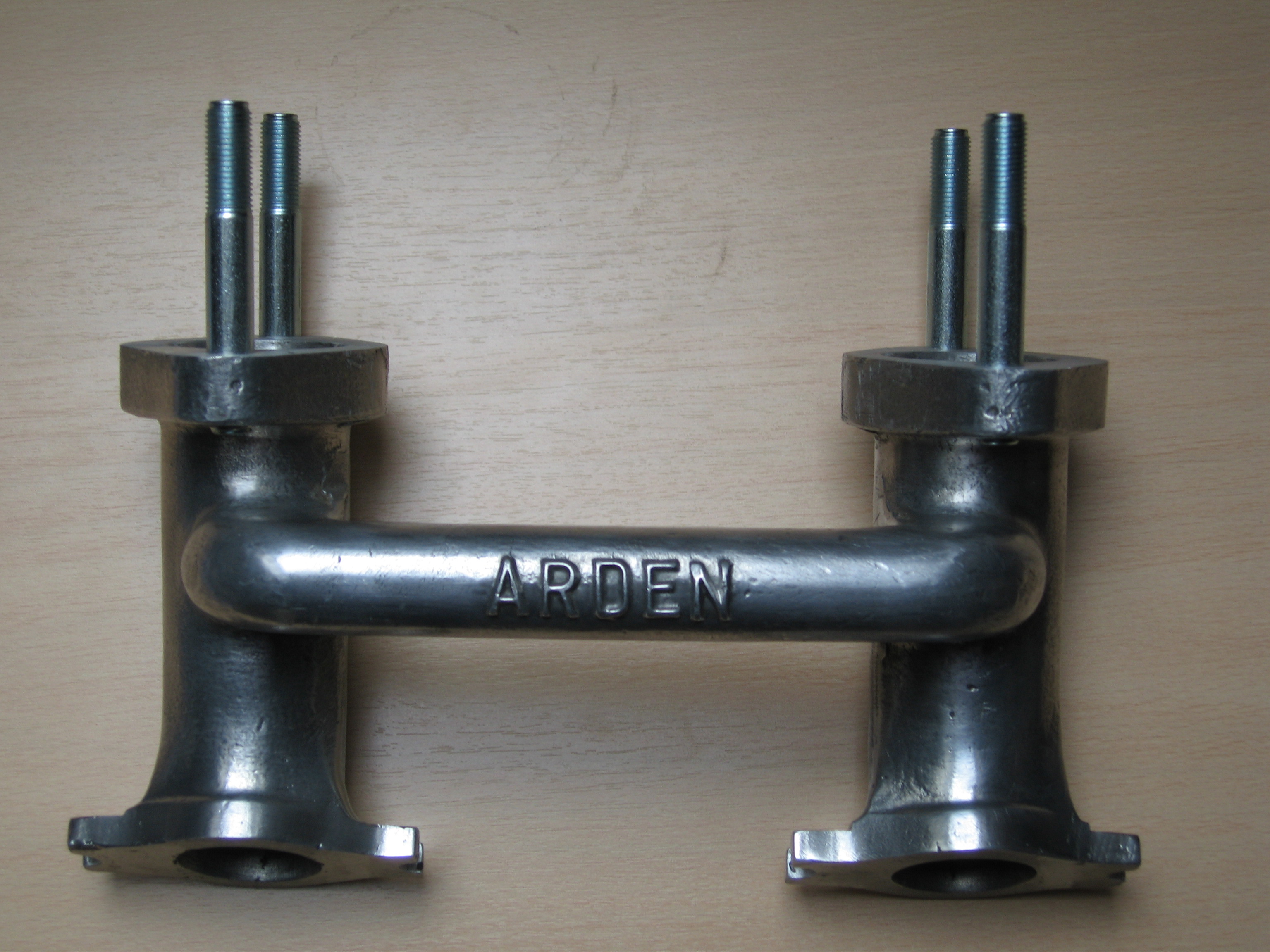
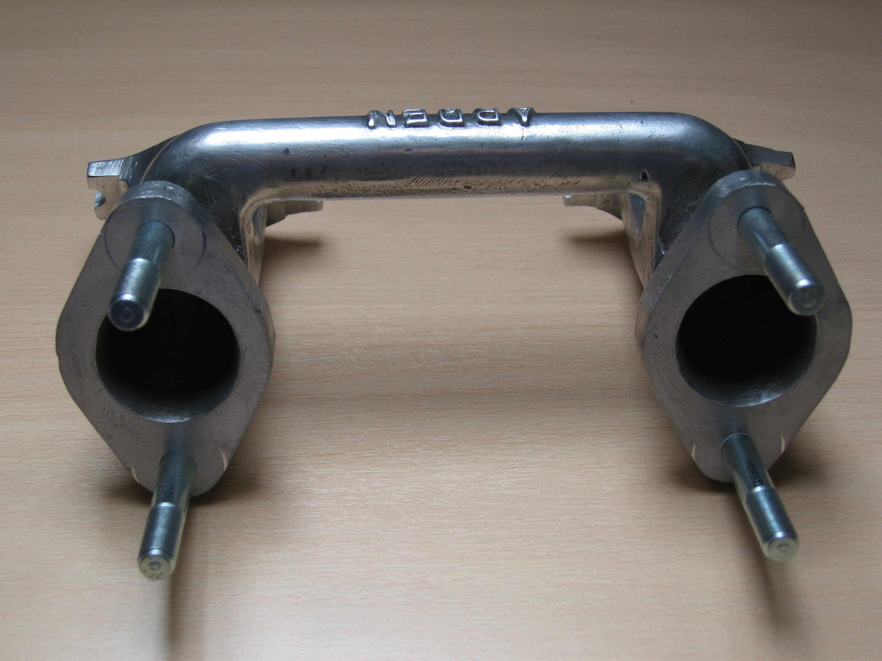
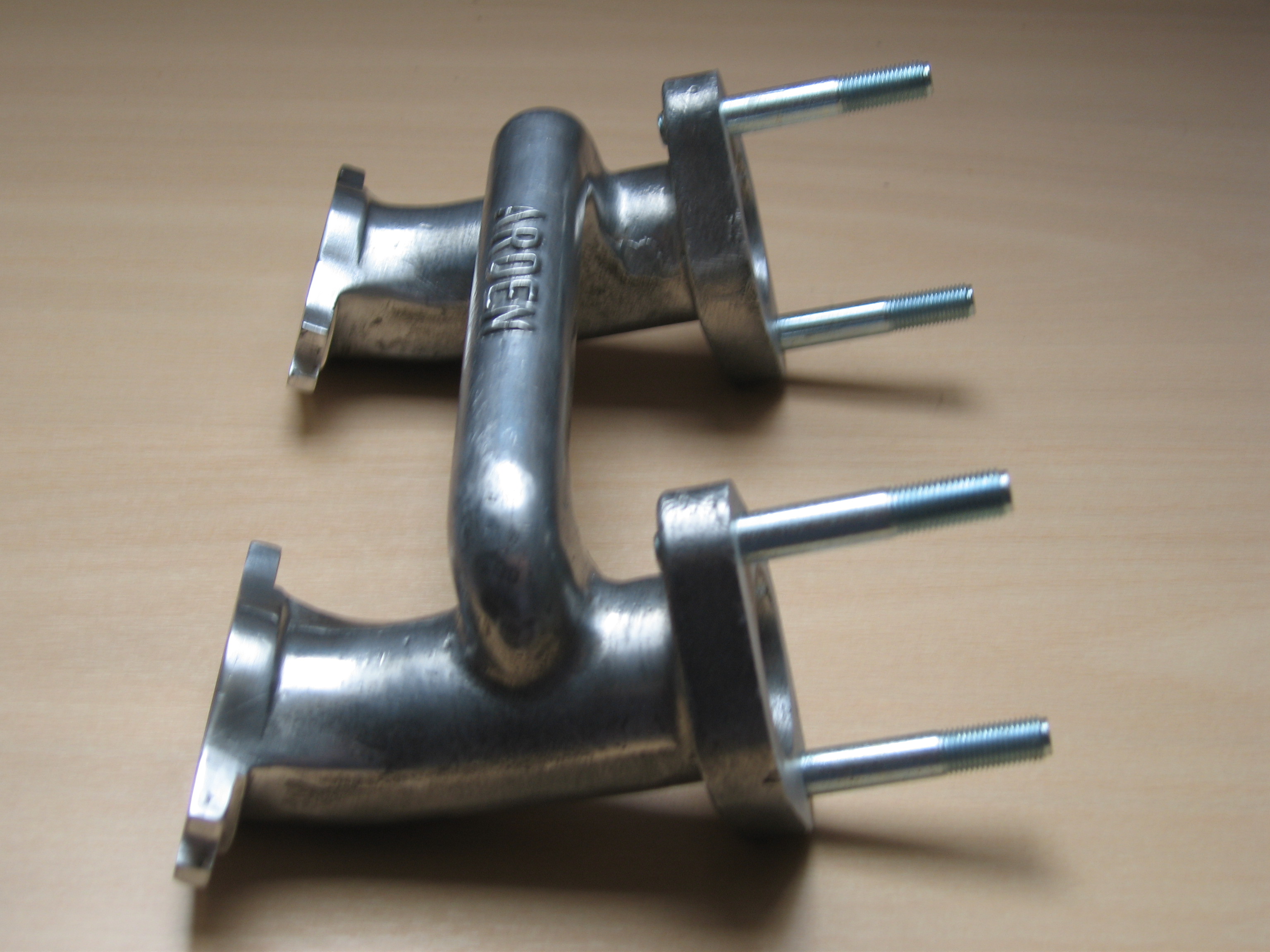
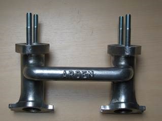
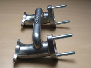
Arden cast alloy inlet manifold
Introduction.
Although my Turner is an Alexander assembled/tuned version, with the car came an Arden inlet manifold. The Arden Racing and Sportscar Ltd or Arden Conversions Ltd. was a tuning company located in Penn Lane, Tanworth-in-Arden, Solihull. Warwickshire. They are especially known for their 8 port BMC-A head as used e.g. on the Mini. In the limited information there is on this company the following catalogue data have been obtained.
Tuned length Arden cast alloy inlet manifold for twin SU 1½” carburettors (1960 – 1962)
Price £ 5. 5. – (in 1962)
Current stud length is based on use of AHH 5713 Phenolic Insulating Gasket for H4 carbs (about 10mm thick). If needed studs can be easily replaced.
Some cracks have been professionally TIG welded and do not impair the functional strength of the manifold. As the manifold has been casted in a (rather pure) Aluminium alloy LM25 (Al Si7 Mg0.5) welding did not cause any problems (unlike with most zinc based alloys like ZAMAK). After welding the flanges have been machined to obtain a perfect mating to the cylinder head.