Introduction
The standard position for the fuel filler for the Turner 950 Sports Mk1 is inside the boot (trunk). The standard Austin A35 fuel tank has been slightly modified, changing the angle of filler pipe in the direction of the centre of the car to have better access to the filler cap with the boot lid open. The risk of spilling some petrol inside the boot is of course present. But another disadvantage was more important for Turners used in racing especially when entering a long distance event (like a Six-hour race): it takes too much time to open the boot lid!
 208JJH at Brands Hatch in October 1960

My Alexander-Turner 950 Mk1 (60-307) therefore had the filler opening repositioned to the outside of the car, just to the right of the boot lid. This has (apparently) been done in the Alexander work shop as this car had the modification from the beginning (March 1960). The above photo taken at Brands Hatch (October 16, 1960) clearly shows that the petrol filler has been moved.
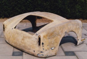 Rear body of 60-307 with original position of external fuel filler still visible
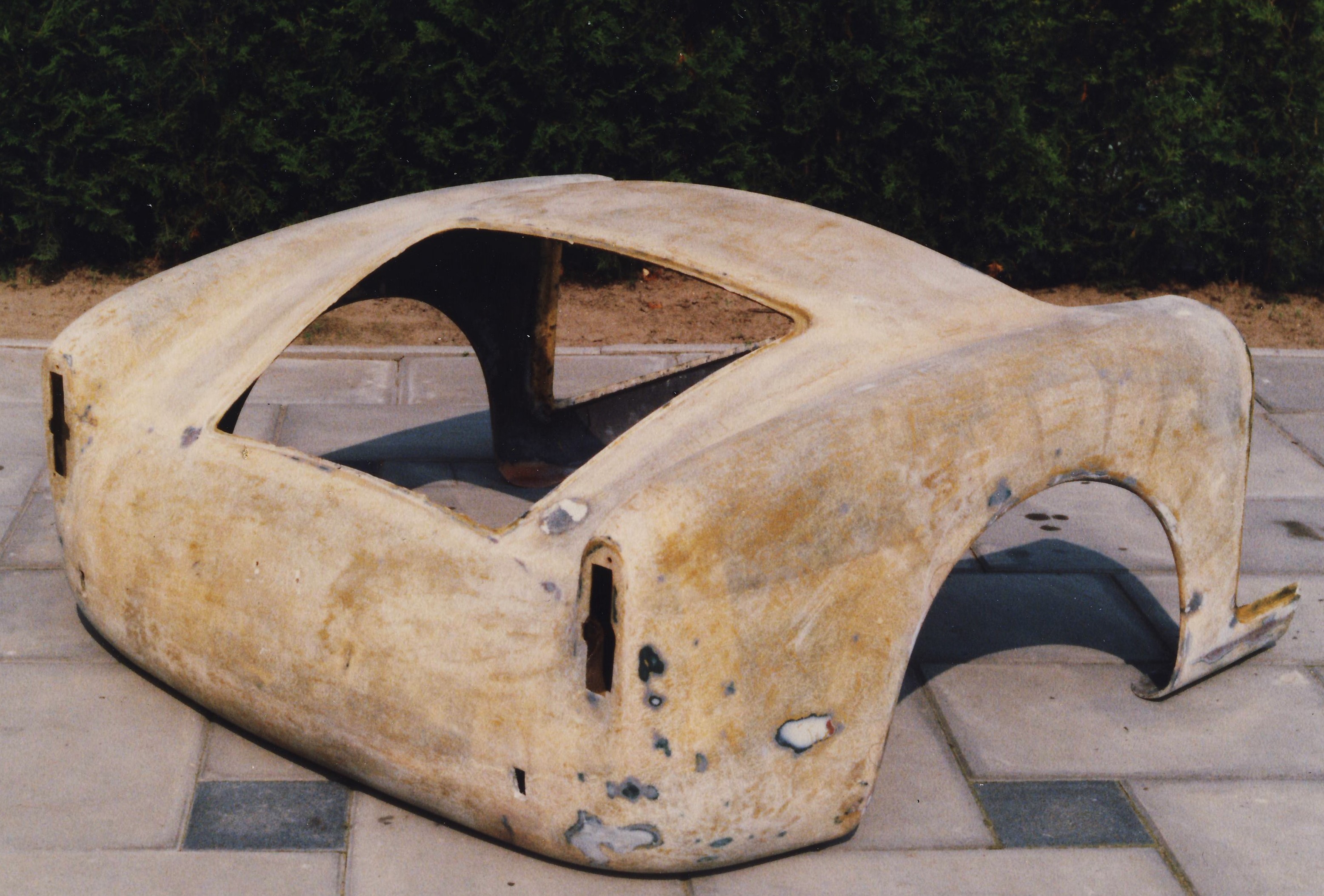
During the restoration of 208JJH I noticed that there used to be a hole in this area that had been closed again with GRP and I thought this could have been a later modification that had been dropped again. On basis of the above photo it is clear that this was the original hole and I recently decided that the car should receive the (original) fuel filler position again.
Modification
The standard pipe connection and hose have a 2¼“ (57 mm) diameter. For the modification we require either a very flexible 2¼“ fuel hose or some pieces of metal pipe of the same diameter bended 45⁰, and some pieces of 2¼“ rubber hose to connect these pipes. Because the standard filler pipe has 30⁰ angle in the opposite direction of where the new filler opening will be positioned, some sharp bends will have to be made in order to have the filler pipe and filler cap positioned in an angle perpendicular to the sloping body at the right side of the boot lid.
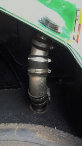 New filler pipe construction

The photo shows the construction of the filler pipe as described, using the original 2¼“ filler cap construction. Found a grommet with an inner diameter of 2¼“ (57mm) suitable for a panel hole of 2¾”or 70mm (grommet for a VW T25 bus used from May 1979 till July 1983). It fitted beautifully in the 70mm hole drilled in the GRP panel.
 Final result; compare with original photo.
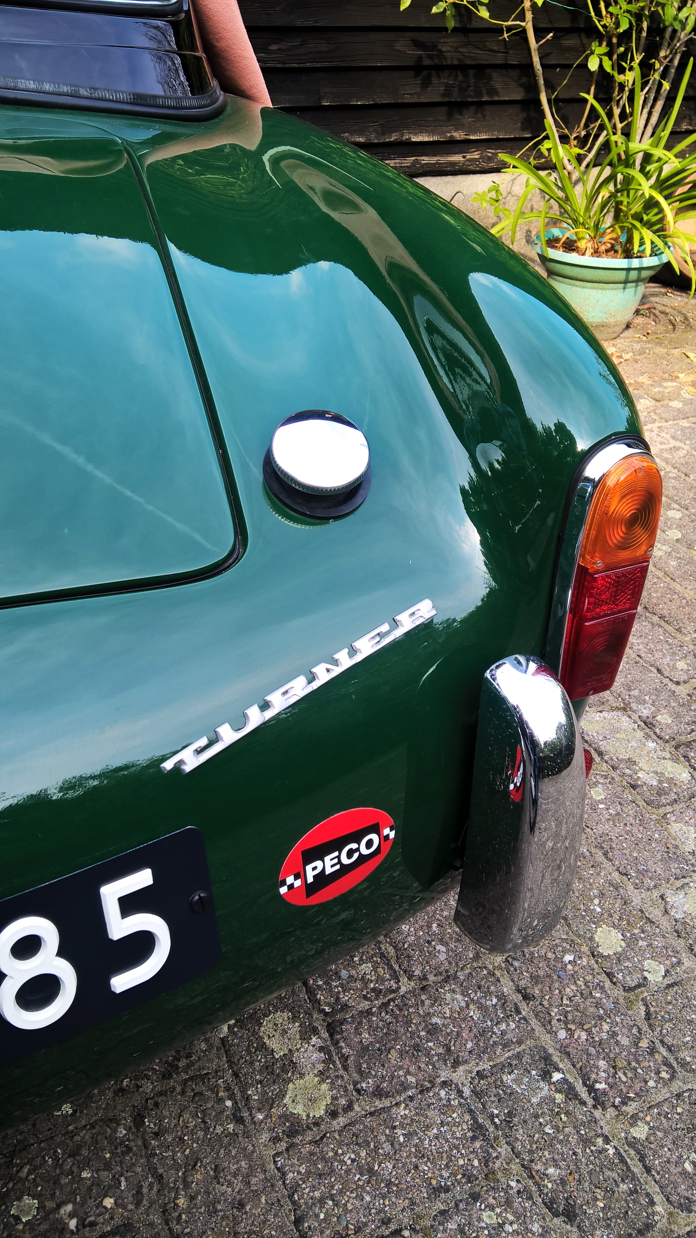
The end result is very pleasing and fully in line with the original photo from 1960.