This article attempts to summarise (in a structured way) information published on the subject of Derrington steering wheels, gathered from various sources.
Chapter 1 The Derrington company
V.W. Derrington Ltd. has been established around 1919 in New Malden, Surrey, England (about 12 miles south-east of London) initially tuning motor cycles of that era. By 1926 they moved to nearby Kingston and became successful in developing and supplying tuning components like manifolds, exhaust pipes, cylinder heads, and other mechanical improvements for automobiles as well as luggage carriers. From 1933 onwards Derrington advertised with steering wheels as part of their business activities.
Victor William Derrington had been a (motorcycle and automobile) race driver himself for many years, allowing him to exploit his racing experience for developing tuning equipment.
After WW2 there were two “fast runners” made at the Derrington works at London Road in Kingston: Derrington luggage racks and Derrington wooden steering wheels available for many models of the 1950’s and 1960’s. According to “Motor Sport” magazine of December 1959, Derrington employed at that moment eight people full time in the production of steering wheels.
Vic Derrington at the 1961 Racing Car Show; note steering wheel at display
Note that over 60% of Derringtons production was exported, the majority to America. The steering wheels were especially popular in the States and several hundreds have been exported every year from about 1953 onwards. Orders for the USA could only be supplied through their West and East Coast agents: Vilem B. Haan in Los Angeles (CA) and Wilco of Rochester (NY).
Front of a 1960 brochure
Chapter 2 The “Derrington wheel” and similar wheels
Although Derrington made steering wheels with various spoke configurations, the company became famous for one particular model that we now call the “Derrington wheel”. The specification of (and additional information on) the “Derrington wheel” is provided in Chapter 3.
As production volume increased, Derrington started to outsource some of the steering wheel activities. By the end of the 1950’s another steering wheel manufacturing company Moto-Lita was capable of providing “Derrington” steering wheels, however it is believed that Moto-Lita made wheels in those days were not of the same high quality as Derrington manufactured wheels.
We may assume that Derrington gradually moved away from steering wheel production, fully concentrating on their successful tuning activities. Probably in the late 60’s Derrington completely ceased their steering wheel production activities and Moto-Lita continued the manufacturing of the typical “Derrington wheel” however always characterised by their standard nine hole centre mounting (see Chapter 4).
A similar wheel was offered by the Donald Healey company for their (Austin-Healey) sports cars, which may lead to confusion. This wheel is therefore further described in Chapter 5.
Finally, the name Derrington is often linked to a Jaguar woodrim steering wheel that was available as an option for the Mk 2. However, this was not the “Derrington wheel” but a different model as is described in Chapter 6.
This brings us to the following timeline for the Derrington (style) wheel:
1953/54 onwards: the “Derrington wheel” manufactured by Derrington in 15, 16 and 17” diameter
1955 onwards: Donald Healey manufactured “Derrington style” steering wheels
1959/60 onwards: Moto-Lita manufactured wheels for Derrington (and Donald Healey)
1960 onwards: Jaguar Mk 2 Derrington steering wheels (different style with non slotted spokes)
Chapter 3 The “Derrington wheel” specification
Around 1953/1954 Derrington started the manufacture and delivery of the “Derrington wheel”. The design itself shows some resemblance to an earlier Italian manufactured Nardi model with three slotted spokes, however not with the characteristically 3 x 120° even spacing of the Derrington wheel.
Derrington had a patent applied for the making of wooden steering wheels on October 18, 1954 and granted on October 5, 1955.
Original patent application of October 18, 1954
Specification and characteristics of the original “Derrington wheel”:
three (slotted) “Birmabright” aluminium spokes with even (3 x 120°) spacing
flat (non-dished) version
eight-hole centre mounting with 8 flat CSK slotted screws and nuts (BSF 3/16 – 32 ?)
laminated rim from mahogany and either obeechi or white sycamore
(nine or) twelve rivets in the laminated rim
The “Derrington wheel” was standard delivered in 16″ diameter, but 15″ and 17″ versions were available to special order. There are also examples of original Derrington manufactured wheels that had a 9 hole centre mounting.
Original Derrington 16” wheel with 8 screw mounting and 12 rivets.
The frames of the wheels were cut from Birmabright (an alloy of aluminium and magnesium with 7% magnesium and 1% manganese; also known as BS NS4, American 5251 and ISO AlMg2), and the laminated wooden rims were riveted to the frame. The laminated woodrim consisted of African Obechi wood and Mahogany. The boss (or hub) is cast from aluminium (mostly LM6) and machined to fit each particular model.
There have been many discussions over the past decades, whether this Derrington wheel was a genuine Jaguar factory option or not. Although apparently more was possible at Jaguars (including a “Bluemels wood rim steering wheel”) than one would understand from the “optional extras” 1958 list, the general opinion is that wooden steering wheels were not available as a factory option, until around 1960 when Jaguar offered a wooden steering wheel for the Mk2 (part number C.25198), but we know that this is actually not the even spaced “Derrington wheel”. Part number C.25198 is mentioned in spare parts bulletins and parts catalogues as well.
We also know that the “Derrington wheel” was rather popular in the 1950’s and was advertised in many car magazines, including those in the USA. Reference is made of the June 1960 issue of Sports Car Illustrated containing ads for the “Well Known Derrington Racing Steering Wheel”. We referred already to the two US Derrington importers, which indicates that Derrington wheels were freely available in the USA. So therefore we may assume that a (large?) number of XK’s may have received an aftermarket Derrington wheel in the 1950’s. Whether or not there was any “active support” from Jaguar USA in supplying these steering wheels remains unclear. Dealers however may have recommended these Derrington wheels themselves in order to increase sales.
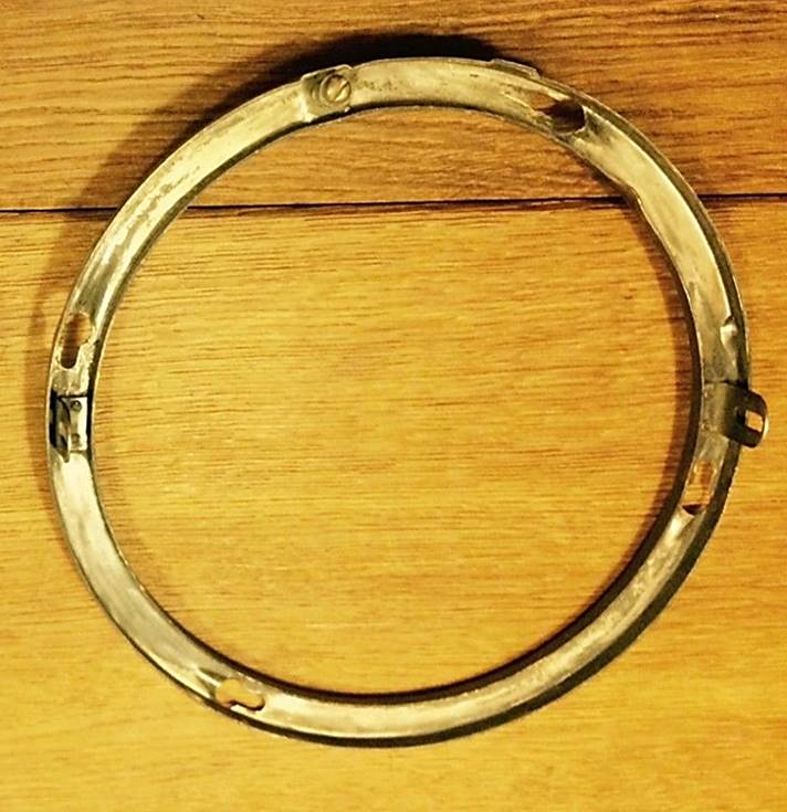
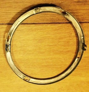
Early Derrington wheel with 8 screw mounting.
The Derrington brochure (shown below, probably dated 1960) not only lists the prices in Pound Sterling but also in US Dollar, which further supports the active marketing policy of Derrington in the USA. Also note the text in the brochure that “practically the entire output for the past few years having been exported”. This may further clarify the presence of Derrington wheels on US Jaguar XK 120, 140 and 150 in the 1950’s.
The list with (only European) car brands and types in the Derrington brochure is long and all Jaguar versions from the period 1950 to 1960 have been listed.
Chapter 4 Moto-Lita manufactured wheels for Derrington (~ 1960 onwards)
Around 1959 Moto-Lita started making steering wheels for Derrington including the famous “Derrington wheel”. Some say that Moto-Lita made wheels of that era were not of the same high quality as Derrington manufactured wheels. Moto-Lita continued the use of 12 rivets but it is unclear whether Moto-Lita was requested to continue the use of 8 bolt centre mounting or that these wheels immediately switched over to the 9 bolt centre mounting boss/hub as already made by Moto-Lita.
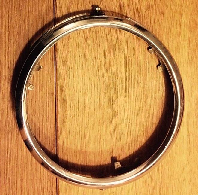
Above is a photo of a 1960’s Derrington wheel made by Moto-Lita. Diameter is 16 inches. It uses the Moto-Lita style hub with 9 screws. Moto-Lita still manufactures the “Derrington wheel” today and adheres to the original design although with 9 bolt centre mounting (see photo below).
The story goes that Donald Healey aimed at in-house production of 16” woodrim steering wheels for the Austin Healey 100 series. The designs were made by Gerry Coker and the first models were manufactured in-house. There were in fact two designs: one with drilled and one with slotted spokes. The latter has a very close resemblance to the “Derrington wheel” with even spaced spokes.
These first versions (also used on the AH 100 Le Mans cars) were made of six separate solid wood segments (not laminated) fixed to the aluminium frame by 4 rivets for each of the 6 per segments (so 24 rivets in total). They had a 9 bolt centre mounting (like Moto-Lita).
Original AH 100 Le Mans “segmented” wheel with 9 screws and 24 rivets in “Derrington” style
The AH 100M could be delivered with the slotted spoke version as a factory option. These wheels were no longer made by Donald Healey but manufactured by the Coventry Timber Bending Co. Ltd . The Coventry Timber Bending Company was a manufacturer of “laminated and solid wood work for cars and boats”. The company had been established in 1938 by their directors: H. E. Newsum and L. G. Hains. They started activities at Swallow Road, Holbrook Lane in Coventry, but later moved to new premises about 5 miles to the east, at Bodmin Road, Walsgrave, also in Coventry. In 1954 they also produced the D-Type Jaguar steering wheel and from 1961 produced the E-Type steering wheel as well. In 1984 the company became Insolvent and was wound up.
The Coventry Timber Bending Co. manufactured “Derrington style” woodrims were made of beech and had only six rivets to fix the wood. The aluminium frame was initially riveted (not bolted) to the boss.
(See for more info: Autocar of December 2, 1962)
Strong resemblance, but not Derrington!
The steering wheel with drilled spokes became the standard wheel on the 100S production cars.
Around 1960 Moto-Lita began to supply “Derrington” style steering wheels to Healey, which now had 18 rivets instead of 24 for the in-house manufactured versions or instead of 6 as made by Coventry Timber Bending. These Moto-Lita steering wheels were Healey badged (or stickered).
Most likely the above photos show the later Moto-Lita made “Derrington wheels” supplied to Donald Healey with 9 screw mounting and 18 rivets! The 6 segment solid wood method has been replaced by a laminated circular construction.
Jaguar, possibly aware of the lively interest in woodrim steering wheels, offered a special 17-inch lightweight, wood-rim steering wheel manufactured by Derrington. It seems that this version was manufactured at the explicit request of Jaguar for use to special order on Mk 2 cars.
The Birmabright spokes had been polished and the woodrim of contrasting laminations of white obeechi and rich red mahogany were clear lacquered to bring out the grain. The Jaguar wheel was priced at £12 and it takes the standard Jaguar Mk 2 half horn-ring.
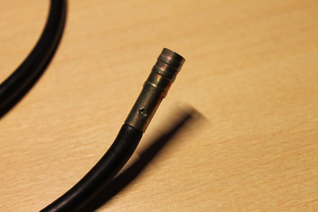
Jaguar used a hydraulic brake light switch on all of their XK models (and many other types as well). This switch is screwed in the Outlet Adapter of the Brake master cylinder.
Brake switches (screw-in type) in general, use different threads which may lead to confusion when looking for the correct replacement. The thread used by Jaguar on these early hydraulic switches is rather special. Finding the correct version is of the utmost importance to avoid leakage or damage to the thread.
All XK brake switch types had an 1/8″ x 27 NPTF (external, male) thread. This is a special screw thread derived from the US National Pipe Thread. NPTF is an abbreviation for National Pipe Taper Fuel and “Oil-dry-seal” thread. This conical thread is designed to provide a leak-free seal. NPTF threads have the same basic shape as NPT but the thread is adjusted to obtain an interference fit, eliminating leakage along the thread. All NPT threads have a taper of 1 : 16 on the outer diameter of the thread, which equals an angle of about 1¾ °.
Male NPTF thread on brake switch
Please note that the corresponding (internal, female) thread of the adapter is 1/8″ x 27 NPSF, which is a straight (non-tapered) thread.
The outer diameter of the 1/8” x 27 NPTF is 10.3 mm and the pitch is 0.94 mm.
The modern version of this brake light switch has a metrical thread coded M10 x 1 and it is therefore easy to get confused and use the wrong version on an XK. Always check whether the correct NPTF thread is being used!!
A third type of brake light switch has an UNF 3/8”x 24 thread (with an external diameter of 9.5 mm). Also avoid this version as (again) the thread will be destroyed by installing this UNF thread.
The following hydraulic brake light switches have been used by Jaguar for their XKs:
1. Jaguar XK 120
Early cars manufactured until January 1953 (chassis numbers up to 660979, 669002, 67048, 679621, 667000 and 677000) had a brake light switch produced by Lockheed: Jaguar code C3901 and Lockheed part number 23388. The switch has long screw studs for the electrical connection and can be easy recognised.
Lockheed Brake light switch 23388
With the introduction of the Tandem brake cylinder type, the XK 120s changed to a Lucas brake light switch with Jaguar code C5218 and Lucas code 31082/B.
Lucas switch 31082/B to F; photo right original Lucas; photo left possible later version
2. Jaguar XK 140
The XK 140 continued the use of the Lucas brake light switch with Jaguar code C5218 and Lucas code 31082/D, mounted in the Outlet Adapter of the Master Cylinder.
3. Jaguar XK 150
The XK 150 also used the same brake light switch but the Lucas number 31082 had meanwhile received suffix F. The switch was mounted in the Outlet Adapter of the Master Cylinder.
Replacement alternatives:
This type of brake light switch can be or was used on many Jaguars : besides the XK120, XK140 and XK150, also on the Mk VII, VIII, IX, the Mk 1, Mk 2 and successors, the E types and even the XJ types
It will be very difficult to find an original C3901 Lockheed switch, but fortunately the later C5218 versions fits without a problem and is still available as an aftermarket version (see list below).
Brake switches for later Jaguar types (code C16062 and Lucas 31802/D) used Lucar connections instead of screw connections, but are otherwise similar.
Jaguar C16062 (Lucas 31802/D) with Lucar connectors
The generic Lucas replacement brake light switch for the 31082 and 31802 is coded Lucas SPB400 but has Lucar connectors.
Other alternatives part numbers: (not all versions have been confirmed)
Gauge for setting front suspension and steering geometry XK 140 and 150
Introduction
A correctly set front suspension (including steering geometry of course) is an absolute must for our XKs. This not only requires a correct ground clearance (torsion bar setting), but also caster and camber values have to be within specifications. The Jaguar Workshop Manual provides a wealth of information for the XK 120 and the Mk VII models on how to adjust the above mentioned items. It also gives additional information on a special “Distance gauge” to be used for setting the (initial) torsion bar position. This distance gauge replaces the shock absorber during the set-up operation.
The “Supplement to the 120 and Mk VII Service Manuals” lists the different settings for the successor models XK 140 and 150, however without giving any information about updated “Distance Gauge” dimensions. In many cases restorers therefore simply take-over the dimensions specified for the XK 120 (or Mk VII).
As the shock absorber dimensions and mounting positions of the XK 140 and 150 are different (compared to the XK 120) it is unlikely that the XK 120 Distance Gauge can be used 1 : 1 for these successor models. In addition the various parameters (ground clearance , caster, camber) mutually affect each other. As these parameters for the XK 120 are quite different, this will be another reason why the Distance Gauge of the XK 120 might be incorrect for setting-up the XK 140 and 150. This article tries to provide additional input in order to define the dimensions for a correct Distance Gauge for the XK 140 and 150.
The two functions of the Jaguar distance gauge.
These gauges have in fact two distances to be used for different purposes:
The longer distance is used when the torsion bars have to be placed in the reaction levers after a complete restoration.
The shorter distance can be used for setting camber and castor and is an “alternative method” of particular use during the restoration process to have a first set-up for the steering geometry when it is impossible to use the “full weight method” as described in the Manual.
For the Mk VII the gauge provides these two distances by choosing one of the two lower holes, whereas for the XK 120 a 2½” long separate distance piece has to be placed on the long threaded top end to get the longer distance.
For the “alternative” camber and caster adjustment method, Jaguar engineers (apparently) determined the exact distance between the two shock absorber mounts for the “nominal” chassis position under full weight. This front wheel position should be identical to the position obtained according the other described method of 7⅛” ground clearance at the “lower face of the most forward parallel section of the chassis frame” under full load. And it should also match the (later) introduced measurement of 11¼” ground clearance “from underside of front cross-member”.
Jaguar XK 120 distance gauge
The Jaguar Workshop Manual provides two drawings of the distance gauges for the XK 120 and Mk VII. The distance gauge for the XK 120 is basically a rod with a threaded top end and a ring welded at the bottom.
The XK 120 gauge consists of a 5/8” (16 mm) steel rod (length about 16” or 405 mm) with a (1”OD) washer welded about 3½” from the top. Using the existing top hole of the Shock Absorber, the top of the distance gauge has a (rare) BSF 11/16” -14 threaded part over a length of 3½” from the top. This BSF thread can be replaced by a UNF 5/8”-14 thread or even an M16x2 metrical thread. At the bottom a 1¼” x ⅝” (32 x 16mm) ring is welded with a mounting hole measuring 21/32”(16.5 mm). The spacer (or distance piece) has a length of 2½” and fits over the threaded top end. An outer diameter of 1” should be sufficient for the spacer. See all other dimensions in the above drawing.
Note that the washer (positioned about 3½” from the top) should touch the lower surface of the shock absorber bracket of the chassis when setting camber and caster.
Jaguar Mk VII distance gauge
As the Mk VII has a shock absorber with two horizontal mountings, the corresponding distance gauge is different. The top of the gauge is now a steel bush with a hole that corresponds to the diameter of the upper fixation bolt (or a bit larger: 15/32” or 12.0 mm). The bottom hole measures 21/32” (16.7 mm) and is identical for both the Mk VII and the XK 120. Note that two lower holes are provided: the lower hole (distance 15⅝”) to be used for setting the torsion bars (ground clearance) and the other (distance 13⅛”) for setting up the steering geometry. The XK 120 and the Mk VII (although different in weight) use apparently the same distance for setting-up the torsion bar position. As we will see later, the actual comparable distance for the Mk VII is larger because of the different (lower) position of the upper shock absorber bolt.
Different shock absorber mountings
The top mounting of the XK 140 & 150 is clearly different: horizontal bolt fixing versus vertical threaded stud on the shock absorber for the XK 120. This will have dimensional consequences for the distance gauge. If we assume that the geometry of the shock absorber bracket welded to the chassis is (more or less) identical for the XK 120 and its successors, then we have to compensate the dimensional difference because of the way the top of the shock absorber is mounted.
Where the distance gauge for the XK 120 touches the underside of the chassis bracket, a new distance gauge for the XK 140 and 150 should be in line with the Mk VII kind of fixation (using a horizontal top bolt). The distance between the underside of the chassis bracket (where the hole is for the shock absorber) and the (centre of the) horizontal hole in the chassis bracket for the XK 140 & 150 is about ⅞” or 21 mm.
A new distance gauge for the XK 140 & 150.
The lowered position of the top bolt (⅞” or 21 mm) affects the dimensions of the new distance gauge.
The longer gauge distance (used for initial torsion bars set-up) will be ((15⅝ – ⅞ =) 14¾” or 375 mm.
The shorter gauge distance (used for setting camber and castor) will be (13⅜ – ⅞ =) 12½ ” or 318 mm.
Potential dimensional deviations of the gauge and their effects
We already mentioned that the XK120 and Mk VII apparently have the same gauge length for setting-up the torsion bars (ground clearance) although the required ground clearance and weight of the cars is different. However, using the aforementioned correction ((⅞” or 21 mm) the theoretical, comparable gauge distance for the XK 120 would be 14¾”or 375 mm. This implies that a lighter car requires a shorter gauge dimension for setting-up the torsion bars, which seems logical.
When the ground clearance was changed for the Mk VII (from 12¼ to 12⅝”) the distance gauge did not change. This may lead to the conclusion that the gauge length is not very critical. Remember that in fact the gauge is only used for the initial positioning of the torsion bar in the “reaction lever” and is always followed by an adjustment of the large bolt and barrel nut. Any deviation will have a limited effect as long as it still fits within the adjustment reach of the reaction lever and leaves sufficient room for adjustment.
For the steering geometry (camber and caster) the gauge is only used for setting the initial steering geometry during restoration or repair. Remember that the gauge distance here is only required to simulate the “nominal” wheel position as present under full load. We noticed a difference in gauge distance between the MK VII (333 mm) and the XK 120 (comparable: 340-21= 319 mm). This shorter gauge distance is apparently caused by two effects: a smaller king pin angle (5° for the XKs versus 8° for the MKs) and a larger caster angle for the XK 120 (initially 5° and later 3°), which again seems logical.
Finally: as the change of the castor angle for the XK 120 from 5° to 3° was no reason for Jaguar to change the distance gauge, the smaller step from 3° to 1¾° for the XK 140 & 150 may have an even smaller impact. Again we are dealing here with the initial set-up of the steering geometry, always to be followed by a professional check with special equipment.
Survey of front suspension and steering geometry specifications
Not commonly known and also not mentioned in the official Spare Parts Catalogue, the Jaguar XK 140 actually did have two different versions of seat frames over its production life. To be more precise: only the DHC and FHC had a revised construction of the seat base and backrest, whereas the OTS continued unchanged until the production of the XK140 ceased in January 1957.
Later seat with revised frame: note new hinge partially visible and hole for earlier hinge in frame
The change-over point in production is around the 20th of March 1956 for both the DHC and FHC. It looks like the new tubular backrest frame was based on the new XK150 frame version (and in fact also used for the Mk1 and Mk2) scheduled for introduction only 12 months later.
Early seat frame construction.
The Jaguar XK 140 DHC and FHC have always shared their seats but the OTS had a different backrest construction (although it kept the same seat base construction). The early seat frames consisted of a RH and LH steel seat base frame and a RH and LH wooden frame with metal strengthening and hinges for the backrests. The seat base frame had holes (Left and Right) for the hinge pivot bolts (BD3255) and two stops for the hinged backrest. The complete early construction has been well described in the Spare Parts Catalogue.
BD9334 RH seat base frame assembly all versions. Seat pan (aluminium)
The seat base frame had an aluminium seat pan which was the basis for the “Dunloppilo Latex Foam Cushioning” (F3508) followed by padding and leather upholstery.
Dunloppilo Latex Foam Cushioning F3508
As can be seen below the early backrests had a fabricated metal strengthening consisting of two sheet metal channels to which the hinges (“dog legs”) had been welded. At the rear and the sides plywood is used, which is the basis for the (“Dunloppilo”) foam rubber cushioning, padding and upholstery.
BD9617 LH seat squab frame assembly DHC/FHC
Later seat frame construction.
For the second version both the base as well as the backrest changed. The backrest now had a metal frame made from round steel tubing that had been flattened for about 2” at the lower end, forming a flat place for the pivot bolt hole. This change towards tubing is probably led by efficiency considerations, which becomes more clear when we compare early and later backrests (see photos) and more in particular the assembly time required for the early version.
Later tubular frame for XK 140 Tubular frame with plywood panels (XK150 shown)
As with the earlier model, plywood was used for the rear of the backrest (fixed to the metal tubes) and the sides, supporting the (“Dunloppilo”) foam rubber cushioning, padding and leather upholstery.
Later seat base frame with higher rear part Original unrestored version
Because the backrest of the seat had changed, the original hinge construction and position could no longer be used and the hinge position had to be changed (about 4” higher and 2” to the rear). A metal strengthening was added at the back of the original base frame (see photo above). Note that the early pivot bolt hole has been kept probably because the early seat base frame was used and modiied. This is also a way to recognize the later seat frame type immediately: the 3/8” hole in the side of the base frame remains clearly visible.
No part numbers have been assigned to this later seat frame type by Jaguar (or at least they have not been published).
Different upholstery for later seat frames
The change in construction of the seat backrest frame also necessitated a change in the upholstery in particular related to the lower hinge part. Some upholstery suppliers therefore ask you to specify whether you have an early or a later XK 140 DHC/FHC seat type.
Old frame (LH) upholstery with exposed hinge; new frame upholstery with covered hinge
After the introduction of the XK120 the first open versions (OTS) had been delivered without any form of direction indicators. The Jaguar Saloons of that period had the so-called “Trafficators” (or “Semaphores”) installed.
Trafficator on Jaguar 1½ litre Saloon
By October 1952 most Jaguar XK120 models had switched over to “flashing direction indicators”, although (according some catalogues) “Home Market” versions may have continued without direction indicators. The XK120 with flashing indicators required “combined bulb functions” at front and rear as no dedicated direction indicator lamps had been foreseen in the initial design.
At the front single filament bulb Lucas 490 side lamps changed to double filament Lucas 513 side lamps with Lucas bulb 361 (12V 6/18W).
At the rear the existing Tail/Stop lamps Lucas model 488 also received an additional function: the 18W brake filament of the Lucas bulb 361 (12V 6/18W) now also acted as flashing indicator.
This was only possible via the installation of a special Lucas double relay (model DB10) that interrupted the brake light in favour of the flashing indicator function when the direction indicator switch was operated. The other brake light kept its normal function to show that the vehicle was braking.
Typical Lucas double relay DB10
The combined direction indicator function for front and rear lamps changed in two steps:
At the front, dedicated Lucas L563 direction indicator lights were fitted late 1954 on the occasion of the introduction of the XK140
Dedicated rear direction indicator lights only arrived in October 1959 when the XK150 changed over to Lucas L627 rear lights with a separate amber or red (USA) direction indicator lens. At that moment also the double relay DB10 was deleted.
The flasher unit.
In the direction indicator system the role of the flasher unit is crucial. The flasher unit is a switch that (in simple words) interrupts the power supply to the bulbs when the current through the wire heats up a spring and restores the connection again when it cools down and all this in a fraction of a second. The rate of flash is normally between 60 and 120 times per minute.
Although difficult to imagine nowadays, the flashing indicator was a new product in England (and the whole of Europe in fact) after WW2 and first development dated from 1949 (Bosch of Germany). In the UK it took until early 1953 before Lucas could supply such units (the FL2 flasher unit) to the British automotive industry.
Introduction of flashers on Jaguar XKs
First flasher units for 1952 Jaguars including XK 120 have been delivered by the Tung-Sol company of Newark, New Jersey, USA. This company (famous for its automotive bulbs but even more for radio tubes) made the first steps towards a “flashing turn devise” in the 1920s. From the 1940s onwards most US car models had these flasher units.
Original Tung-Sol 241D Later version
The Tung-Sol flasher unit is a complex devise using both “thermal expansion” of the metal arms as well as “electro-magnetism” to open and close the points.
The flasher used by Jaguar was part number Tung-Sol 241D which is a flasher units suitable for switching 2 x 21W (total 42W) including a (“Trafficator”) warning light. Jaguar used in that period 2 x 18W bulb power plus a 2.2W warning light in the instrument panel (total power about 38W).
Note the following Service Bulletin 112 of October 1952: “Cars scheduled for export are fully wired for flashing indicators and have relay units fitted. Owing to shortage of supplies, Tung-Sol unit part number 241D is not included for certain countries, and it is the responsibility of the Distributor to ensure that unit is obtained locally and fitted prior to delivery”.
The Jaguar part number for the Tung-Sol 241D flasher was C5230.
The Tung-Sol flasher has three screw contacts at the bottom marked + (for battery), L (for direction indicator lamps to be switched) and P (for pilot or warning light). The flasher had a vertical bracket with mounting hole. Also note that the early Tung-Sol flashers had the product data printed in black on the aluminium can.
Change-over to Lucas flashers
Lucas had developed in the meantime their first flasher units. The FL2 (Lucas part number FL35002) had been introduced early 1953. A revised version model FL3 arrived late 1953 with Lucas part number 35003/A which was consequently used in the XK120 production. Note that Jaguar part number remained C5230.
Lucas FL 3 35003A
The Lucas FL3 flasher unit is basically identical to the earlier Tung-Sol version. Also note the exact details of the (copied) screw connections. Even the marking was identical apart from + which changed into B (for battery); remember Jaguars had positive earth. Also Lucas started with printed product data on the outside of the aluminium flasher housing. This flasher also had a vertical bracket with mounting hole.
The Lucas FL3 (35003A) was continued for the year 1954 when the Jaguar XK140 was introduced and remained standard fitment until early 1957. The XK 140 received dedicated direction indicator lamps at the front (Lucas L563) and thus the Lucas 513 side lamps changed from double filament to single filament bulb holders with Lucas bulb 207 (12V 6W). We note that all Jaguar XK 140s had the FL3 as standard equipment.
From FL3 to FL5 flasher units
Early 1957 the FL3 was replaced by the FL5 flasher unit (Lucas part number 35010A). Jaguar part number remained (again) C5230. The internal construction had changed and the aluminium housing had a larger diameter but it was shorter than the FL3.
Comparison FL3 versus FL5 (courtesy Marvin Moore)
The FL5 remained the standard version for many years until it was replaced in the 1980s by the 8FL version.
FL5 flasher 35010A
The FL5 flashers kept the 3 screw connections and the marking was still B, L and P. But Lucas changed from printed to stamped product data on the outside of the aluminium flasher housing. The 35010 flasher continued the vertical bracket with mounting hole.
The Jaguar XK150 started life in February 1957 with the new Lucas FL5 flasher. It continued the direction indicator lamps (front and aft) of the Jaguar XK140 until dedicated rear direction indicator lights arrived in October 1959. The XK150 changed over to Lucas L627 rear lights with a separate amber (or red for USA) direction indicator lens. At this moment also the double relay DB10 was deleted.
Overview of flasher versions for XK120, 140 and 150.
Lucas Flasher product range
Lucas extended their range of flasher units gradually over the years. In fact only the FL3 and FL5 models are of interest to the Jaguar XK owner. As far as originality is concerned, the FL3 version is by now almost impossible to find but the early FL5 version with 3 screw contacts can still be found as it has been manufactured until the 1970s in large quantities.
Survey of Lucas FL3 and FL5 flashers
Lucas introduced the “Lucar” connectors (replacing the screw contacts) in 1960. These flasher versions are (functionally) identical to the earlier 35010 version, apart from the Lucar connections at the bottom. We are also looking for a vertical bracket with mounting hole, because there are also other versions without a vertical bracket, e.g. Lucas 35011. These flashers require a separate mounting clip and also sometimes have a special connector which looks very similar to a 3 pin bulb holder as used for Sealed Beam lamps in the 50s and 60s. This construction allows for a quick replacement of a defective flasher unit. Note that in some cases the connector block is fixed to the car body with a screw (RH photo below).
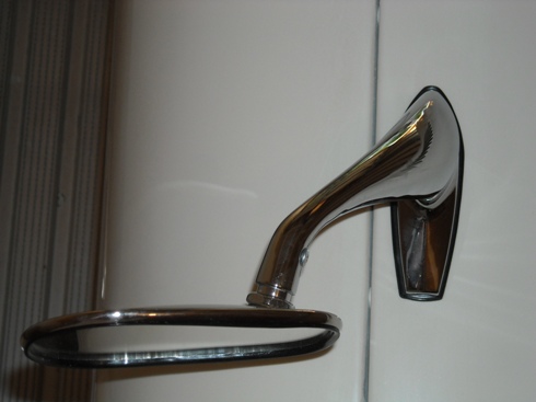
Known for their electrical equipment, Lucas also had a large range of rear view mirrors in their programme from the 1930s onwards. It is therefore logical that Jaguar first had a look at the Lucas mirror portfolio. Next to Lucas there were a large number of other (pre-war) mirror manufacturers like Wingard, Magnatex (TEX), Raydyot, Desmo, and many others. We have to note that in the 1940s and 1950s there were many countries without a legal obligation to have exterior mirrors and therefore these mirrors were only offered as an “optional extra” or even to be purchased by the owner as an aftermarket product. In (some states of) the USA, however, it was necessary to have one exterior mirror mounted at the driver side.
1937 Lucas catalogue; note that Lucas 406 mirror dates from 1937
Wing (fender) mirrors for Jaguars: the 406 series with convex glass.
“First generation” Lucas 406
In the mid-Thirties Lucas introduced the “Lucas 406 exterior mirror for mud-wing mounting” which was available as Nearside and Offside version. The 1939 Lucas Catalogue 400B refers to an outer diameter of 4 3/16 inch or 106 mm and lists the following part numbers:
406/29-OS 580.733 406/41-NS 580.736
The Lucas 406 series exterior mirror is mounted with a single bolt (5/16” BSF) through the front wing. It has a chromium plated round mirror head, and was available with convex glass only. The mirror head is adjustable and is secured by a clamp using 3 screws. This implies that all Jaguars manufactured before the mid sixties could have convex mirrors only. Flat glass mirrors are a later addition or replacement.
Original 406/29 convex glass mirror and box
The Jaguar Mark V parts catalogue lists the Lucas 406 mirror 580733/A for RHD and 580736/A for LHD. Apparently only one side was supposed to get a mirror installed on the wing above the front wheel. We also find the description (supporting this) that some Jaguars only had an “O/S mirror” (off side or passenger side).
The RH(D) mirror Lucas part number 580733 is known as Lucas model406/29: this a chromium plated 4¼” round exterior mirror with mounting Bracket 620783. Similarly, LH(D) mirror Lucas part number 580736 is Lucas model 406/41 and is fully identical apart from the Bracket, now part number 620784: the two brackets are “handed”. Note that the indication /29 and /41 relate to the type of Bracket used; this number is also found on the base of the brackets.
The Jaguar XK120 didn’t have the (factory) option to order exterior (wing) mirrors, but there are sufficient photos around to proof that the Lucas 406 mirror was used on the XK120. The most famous is possibly NUB120 which had the first generation Lucas 406/29 and 406/41 from 1950 onwards.
NUB 120 with early Lucas 406 mirror
Please note that on NUB 120:
The mirrors have been switched: the RH mirror is now on the LH side, possibly in an attempt to keep the mirrors within the maximum width of the car.
The mirrors have been placed much closer to the driver and not on the top of the wing above the front wheels as later XKs normally have.
“Second generation” Lucas 406
Early 1953 Lucas introduced an improved version of the 406 series, which was indicated by adding suffixes to the Model number and by a new part number:
Model 406/29 became 406/1/29A with new Lucas part number 062587.
Model 406/41 became 406/1/41A with new Lucas part number 062590.
Note that the mounting Bracket (or stem) did not change with the new version and remained 620783 for RH and 620784 for LH.
As mentioned before all 406 mirrors originally had convex mirror glass, meaning the viewing angle was larger but the reflected image itself smaller. Later a flat glass version was added to the range.
The Lucas “Advance Information” catalogue for 1955 jaguar Cars (issued February 1955) mentiones these newer 406 mirrors (Lucas 062587 and 062590) for the Jaguar Mk VII, but “Export only”. The corresponding Jaguar part number is C9091 (with a rubber pad C9904 for the fitting). As stated, initially only as an option for (export) Mk VIIs but later as standard fitment for the Jaguar Mk VIIM.
“Salesman’s Data Book” XK 140 listing wing mirrors
According the Spare Parts Catalogue the XK140 still didn’t have the (factory) option to order exterior (wing) mirrors. But the 1955 “Salesman’s Data Book”for the XK140 (and Mark VII M) clearly states that wing mirrors were available as “Jaguar Approved Accessories and Extras”. Also some photos from the mid 50s show XKs with either a single (driver side) or double wing mirrors. Dealers may have also ordered spare Mk VII wing mirrors (C9091) and holes were drilled to mount them.
Lucas 406 mirror dimensions
Technical details of the Lucas 406 range (second generation 1953 onwards)
Lucas wing mirror RH Model 406/1/29A Part number 062587
Lucas wing mirror LH Model 406/1/41A Part number 062590
Mirror head 406/1 Part number 62540A stamped on mounting flange
Original 406/1 65240A three screw mirror head
Screw, ball clamping fixing Part number 655453 (3 pcs) RCSK slotted chromed 4BA x ½”
Ball clamp (stamped “Lucas Made in England”) Part number 620786
Original ball clamp
Bracket assembly RH Part number 621740
Bracket assembly LH Part number 621749
Nut (BSF5/16 x 22), brass cadmium plated, fixing mirror to wing Part number 182519
Washer shake proof for Nut 182519 Part number 188471
Washer, plain, OD 1½ “, under wing Part number 580735
Pad, rubber, base Part number 580734
Text on original rubber pad: LEW 16
Bracket RH Part number 620783
Bracket LH Part number 620784
Note the Bracket models numbers 29A and 41A next to the part numbers casted in the base.
The mirror glass is held in the chromed mirror head by folding the outer rim over the glass (in a rotational process). The glass is sealed by a rubber ring and backed by thick paper. See photo.
Photo Tadeusz Malkiewicz
Addition of flat glass mirrors: the Lucas 407 range
Late 1959 or early 1960 a flat glass range was added next to the model 406. The new versions were 407/29 (for RH) and 407/41 for LH mirrors. Also note that the Lucas part number was no longer stamped on the mirror head. A complete survey of 1967 Lucas catalogue numbers under the chapter “Recommended Accessories”:
Model number 406/29 (RH) convex glass: 59061047
Model number 406/41 (LH) convex glass: 59061049
Model number 407/29 (RH) flat glass: 59061055
Model number 407/41 (LH) flat glass: 59061056
Model number 407 (LH=RH) flat glass 59061057 (see next paragraph)
New box for 407/29 (59061055) flat glass mirror Lucas 407/41 (59061056) flat glass mirror
Lucas 59061047 LH Convex mirror Lucas 407/41A but other code 54061029
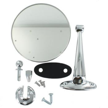
“Third generation” Lucas 407/112; symmetrical two screw mounting
This version was introduced late 1959 or early 1960. It is based on the (new) flat glass 407 mirror head but received a new bracket (Lucas 112) that could be used both left and right . This model was about 15% cheaper than the 406 or 40729 and 407/41 models, that remained however in the programme. Some Jaguar XK150s and some E-types have been seen with these mirrors from new, but it is unclear whether this is a factory (optional extra) mounted version or a later addition.
Lucas 407/112
The change implied a new type of Bracket (Lucas 112) which was now mounted on wing, pillar or door using 2 self-tapping screws instead of the single larger (5/16”) bolt of the previous two generations. This change necessitated a different base to create sufficient space for the two screws. This mirror is indicated as Model 407/112 and the part number for the complete mirror is 59061057 (dated 1967). The Bracket Lucas 112 has part number 521545 and “BS 1004A” casted in the base (the latter being the early British Standard for “Specification for zinc alloys for die casting”). Model 407/112 was never offered with a convex mirror head, also because now the mirror could be mounted closer to the driver. The way the mirror had to be adjusted remained the same.
Later model 407/112 flat glass mirror with symmetrical base and 2 screw mount; Lucas 59061057
The C.9091 (the “second generation” 406, made by Lucas) was most likely initially continued when the XK150 was introduced in 1957. For the first time the wing mirror was included in the Spare Parts Catalogue as an “optional extra” that could be ordered from the factory. The XK 150 Spare Parts Catalogue mentiones part number C.16114 for the wing mirrors; this may refer to the modified Lucas model 407/112 with Lucas part number 59061057 (see above) as supplied from 1959/1960.
This (third generation) Lucas mirror type is also seen on (Series 1) E Types, although TEX mirror types may have been used as well around that time.
Other Lucas wing mirrors
Characteristically the Lucas 406/407 type of mirrors all used a 3 screw clamp for mounting the mirror head to the bracket/stem. As we have seen above, different brackets have been added to the programme (see also example “third generation”) but we have seen more bracket versions: see unknown example below. Model number unknown.
Unknown Lucas model number
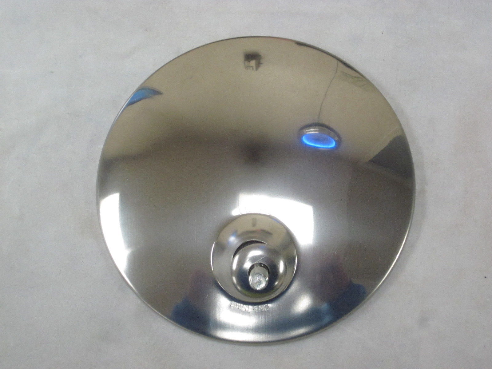
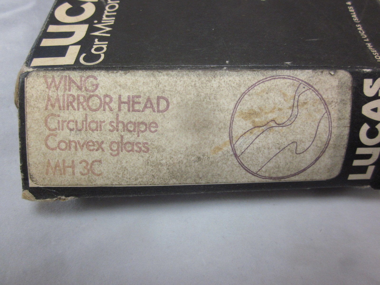
Years later (1970s) Lucas switched over to a new mirror head fixation (MH 3) with a single bolt permanently attached to the mirror head. These mirror heads are no longer interchangeable with the 406 kind of mirror heads. This fixation system is more or less identical to e.g. the TEX system. The convex mirror head was coded MH 3C and we may assume that the flat mirror was coded MH 3F (unconfirmed).
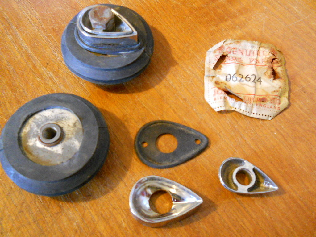
As we will see later, Magnatex had meanwhile introduced the so-called “spring back” system whereby the complete mirror was mounted on a spring mechanism allowing the assembly to flex in case someone/something hits the mirror. Lucas’ answer was to use special mounts to be placed between the existing mirror base and the wing (fender). These wing mirror “spring back” type of mounts had part number Lucas 062624. These mounts included a spring mechanism encased in rubber. The screw on the photo is only for packaging/transportation purposes.
Special Lucas kit 062624 for “Spring back” upgrade
Change-over from Lucas to TEX (Magnatex)
(Magnatex Limited in 1962: Bath Road, Harlington, Hayes, Middlesex, UK.)
In the early 1960s a (gradual?) change-over took place whereby Lucas mirrors were replaced by mirrors manufactured by Magnatex under the brand name TEX. Lucas catalogue CCE 906/62 of April 1962 “Quality Equipment and Spare Parts 1962 – Jaguar” only lists an Interior Mirror (Lucas 680) and no exterior mirrors any more. However, we do know that the supply of Lucas model 406 and 407 exterior mirrors continued until the early 1970s.
This is a rather difficult period to establish which mirror version was used on what model. In the early 60s we see mirrors on the XK 150 (and the Mk VIII as well) that sometimes are Lucas while others are TEX. Of course this could also be a mix of “factory optional extras” and dealer mounted mirrors, but the information available does not provide a clear timing for the change-overs. Some input for discussion:
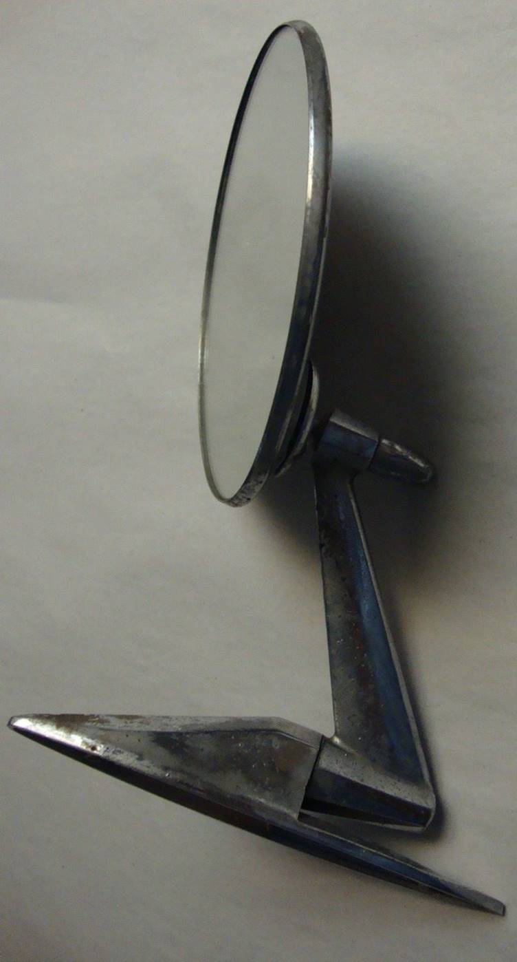
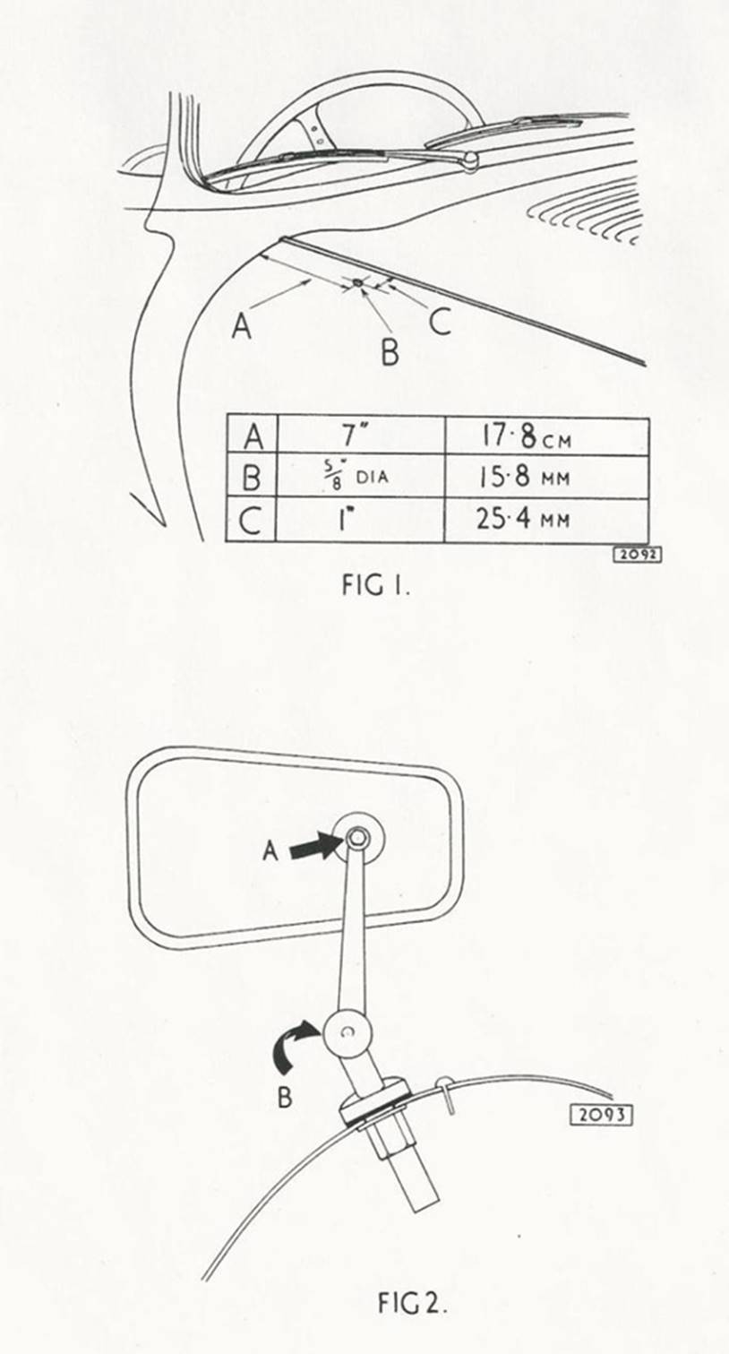
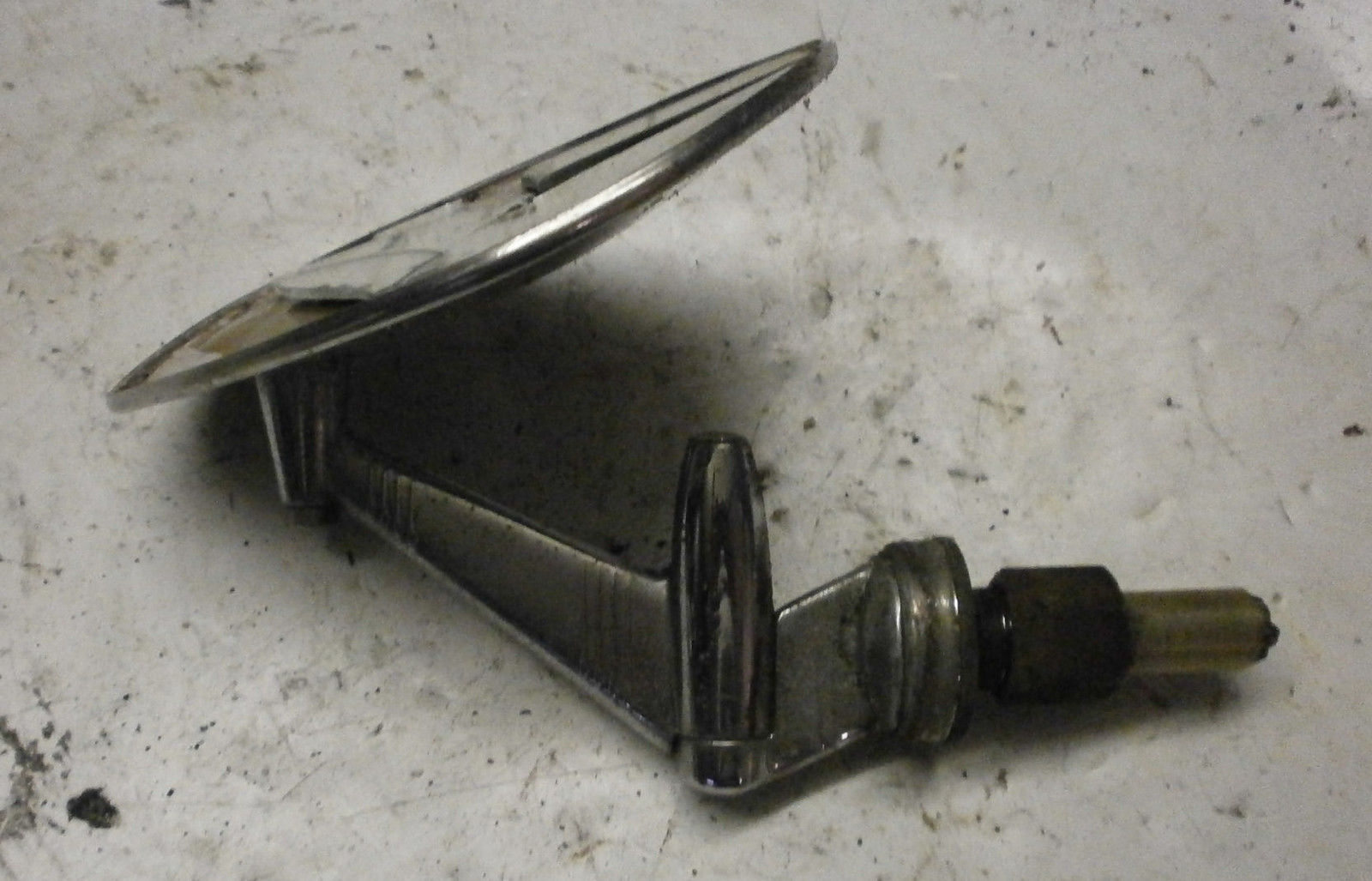
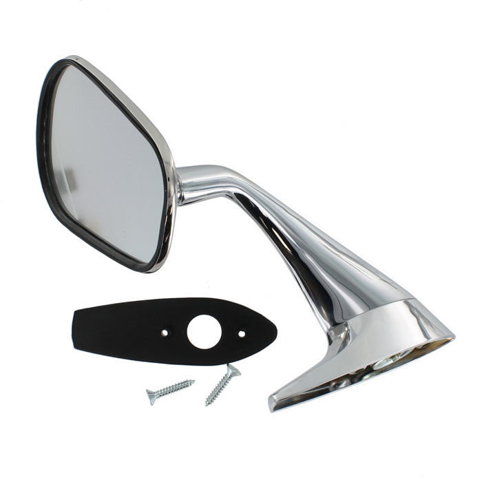
According the Spare Parts Catalogue the Jaguar XK 150 (and the Mk VIII) received a revised wing mirror with Jaguar part no. C16114 for both sides in the early 60s. After the introduction of the E-Type in 1961 this mirror was also an “optional extra” on this car. This mirror, manufactured by Magnatex (TEX), had a spring loaded base, curved arm, round head and a flat mirror glass. It was no longer handed but fits the LH or RH side because the mirror head can be installed from two sides. There are apparently two versions of this wing mirror: Jaguar C16114 and Jaguar C16114/1 which have the same stem (bracket) but the first has a round mirror head while the latter has a (tapered) rectangular shaped mirror head. Most Jaguar part suppliers of today provide these mirror types as part number C16114 (or C16114/1).
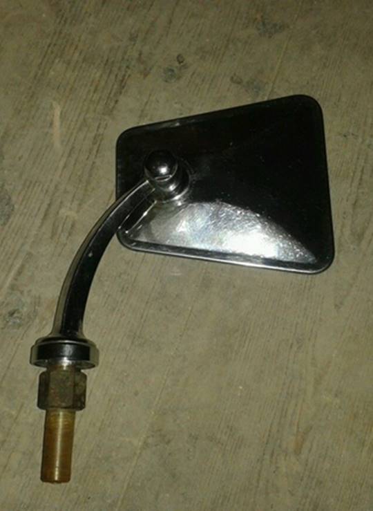
Jaguar C16114/1 with “continental” mirror head
The Jaguar Mk IX (1959 – 1961) also had two C16114 Wing Mirrors available as “Optional Extras”. They were mounted on a line 1″ outside a straight line from the (red plastic) indicator in the sidelamp casing, and vertically, on a straight line up from the centers of the wheel hubs.
The use of Jaguar C16114/1, however, may have been short lived as becomes clear from Jaguar’s proposed solution in Bulletin A.13 dated December 1961. This bulletin describes a TEX “Viewmaster” adjustable mirror bracket of the “Spring Back” type with “Continental” type mirror head : this “Continental” mirror head type is (tapered) rectangular and no longer round. Also note that the mirror is placed on the bonnet (hood) of the E-Type. This TEX mirror apparently received Jaguar part number C19909. These mirrorrs were supplied with the car but not installed because of transport problems.
C19909 from 1968
So it looks like wing mirror C16114 was replaced soon after its introduction by Jaguar part number C 19909 which is defined as Magnatex M2VC/6C. This C19909 wing (fender) mirror was fitted to cars exported to countries where external mirrors were compulsory like Belgium, Denmark, France, Germany, Holland, Luxembourg or Switzerland. It was also supplied to special order.
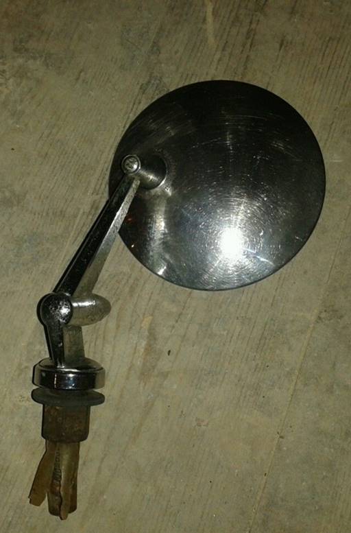
The same TEX system could also be supplied with a round mirror head, as can be seen on the photo below. This type of adjustable bracket has been used on Jaguars from the early till the mid 60s (e.g Jaguar S-type).
TEX adjustable bracket with round mirror head
Later Jaguar Mk10 and 420G cars had wing mirrors Jaguar part number C20819 with additional description MC120/6C which we assume is also made by TEX. This (most likely) is the last wing mirror used by Jaguar after which only door mounted mirrors were used as exterior mirrors. Jaguar Service bulletin A 15 dated July 1962 shows the correct position 14 1/2 inches back from the edge of the outboard lamp. It also shows a drawing of the correct mirror C20819.
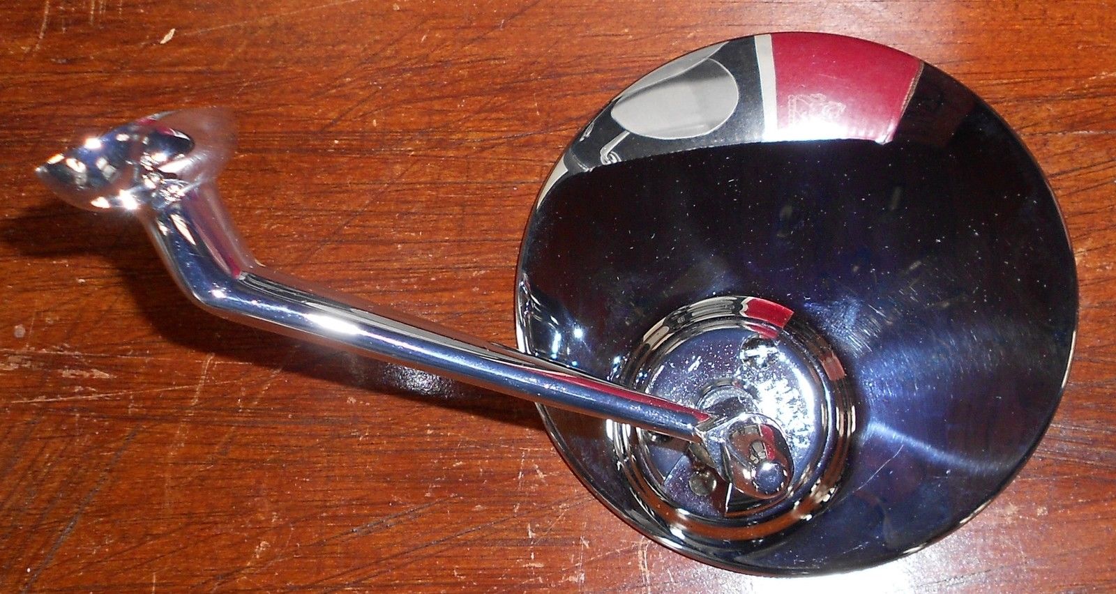
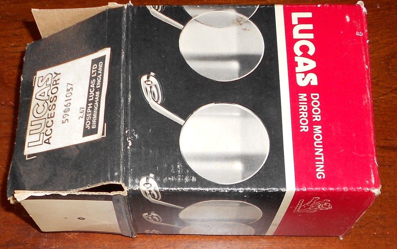
For the year 1968 all LHD E-Types got a new LH door mounted mirrorJaguar C.28517 which is also described as SA365 (which might be a TEX number). The matching RH door mirror has Jaguar code C30827. This mirror is also known as the “Swan Neck” and can also be (or has been) used as a wing mirror. This mirror is mounted using two self-tapping screws and a hole (special shape) that allows the use of two speednuts in the door skin or wing. This mirror is still available.
Door mounted Jaguar C28517 “Swan Neck” mirror. Also wing mounted on e.g. later E-Type (Right)
Modern replacements
The “Lucas type” wing mirror is newly available from most parts suppliers, but in many cases these are not entirely identical to the original version (either generation 1 or 2):
The Clamp part number 620786 is often not stamped “Lucas Made in England”.
The casted (part) numbers at the underside of the Brackets have been deleted.
The 3 screws for the clamp should be of the “raised countersunk” type with a slot, whereas the modern versions have “pan head” crosshead screws.
Modern replica “Lucas style”
However, based on the data provided in this survey, it should be possible to find a contemporary (derived) version that still has the required correct parts.
For the more specific types (example “third generation”) it will be much more difficult, but they are offered from time to time on e.g. Ebay.
TEX mirrors are still manufactured today, although not always completely identical to the specific version you might be looking for.
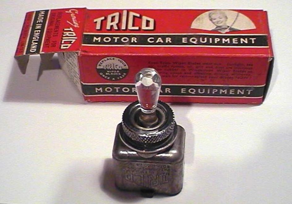
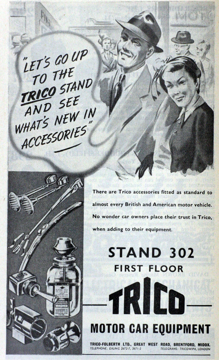
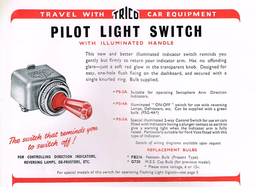
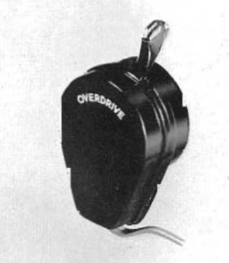
Besides the well-known vacuum equipment for wipers and washers, Trico also manufactured a large variety of switches as part of their programme for the automotive industry. One of the most “famous” versions is the PS (Pilot light Switch) range with an illuminated, transparent handle. This is a specific UK developed and manufactured product.
Switches have been supplied during the 1950s and 1960s after which production in the UK ceased.
1951 advertisement with Trico PS type of switch
The Trico PS (Pilot light Switch) range.
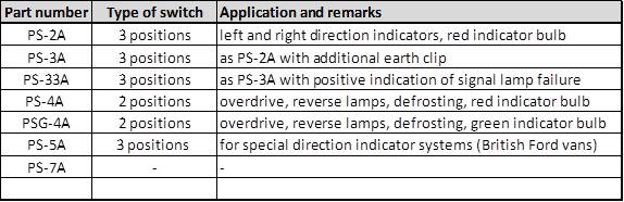
The range consisted of at least 7 versions (but possibly more), each one intended for a specific application like:
2 or 3 positions (1 way or 2 way switch)
specific load to be switched
which signalling function required
required bulb colour
6 Volt or 12 Volt execution
The switch is to be mounted in a panel using a ⅝” or 16 mm hole. A chromed knurled ring, acting as nut, secures the switch to the panel.
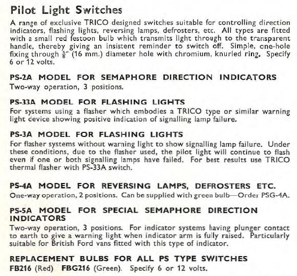
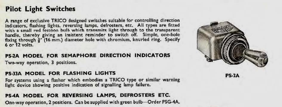
Survey of PS switches
Catalogue 1953 (courtesy Roger Payne)
Catalogue 1959 Catalogue 1960
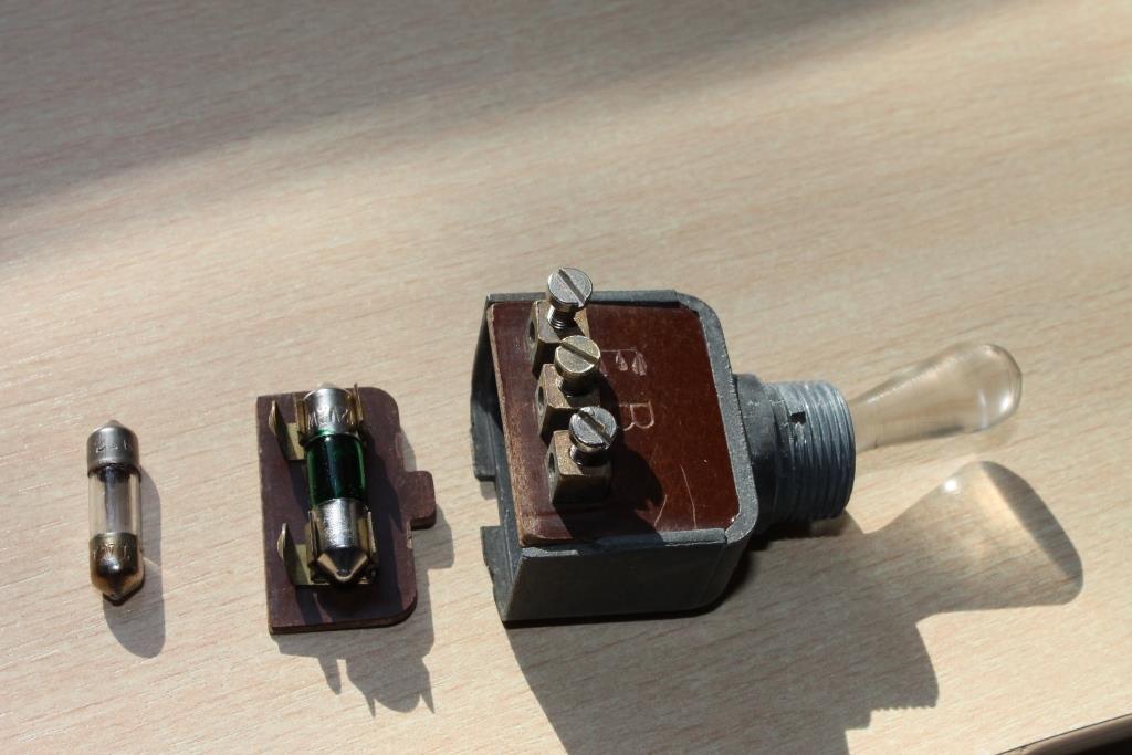
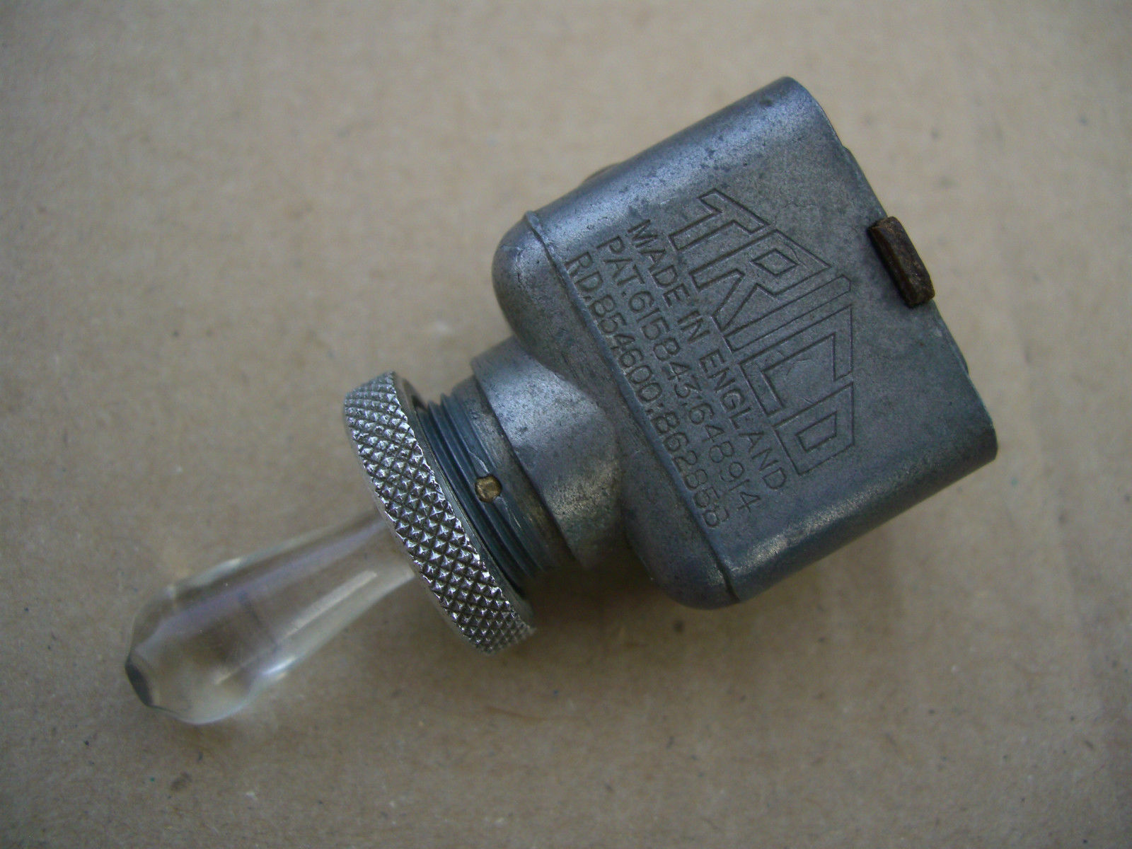
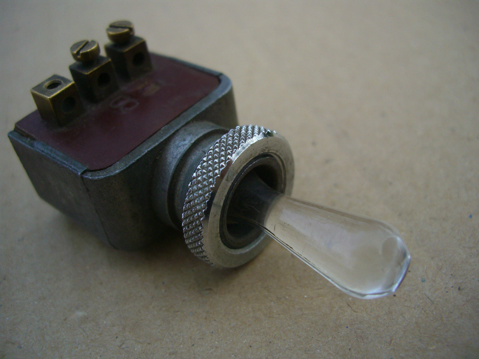
The PS switch construction
All switches used the same aluminium die cast housing, suitable for 3 positions. The signal lamp was positioned on a (thermoset) plastic cover at the bottom of the switch, whereby the number and position of contacts depended on the signalling function.
In case of a 2 position switch a rubber buffer was placed at one side within the aluminium housing blocking the 3rd position.
Typical construction
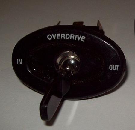
Jaguar application of the PSG-4A switch
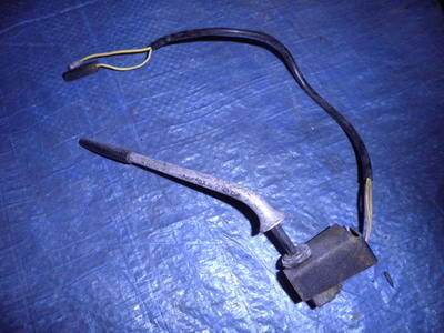
Although Lucas recommended their manual overdrive switch type 9RW (Lucas part number 31587 or 031648) in combination with Laycock overdrives, Jaguar instead opted for a Trico switch in spite of the very close relation with their “preferred supplier”.
Lucas overdrive switch 9RW used on Armstrong Siddeley and Triumph
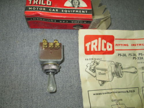
In 1954 Jaguar introduced the PSG-4A as an overdrive switch on the XK140 (and other contemporary models like the Jaguar Mk VIIM and Jaguar Mk1) with Jaguar part number C7474. This switch had 3 screw terminals of which two were marked: the middle had the letter B (battery) and the other with the letter E (earthing the signal bulb). The third (unmarked) contact is connected to the Overdrive Relay(s). This switch originally had a green “festoon” bulb (although many may have received a white replacement bulb in the past decades). The replacement Trico bulb FBG216 received Jaguar part number C8829.
Note that the PS-4A version is normally supplied with a red bulb, but Jaguar opted for the green bulb.
Note: For the XK150 Jaguar changed over to part number C12832 (81053 JSB) which is not further discussed here. Also the Mk2 used a different (Lucas) switch type 52SA with Jaguar part number C15611 (Lucas part number 31965A) followed by SA52 type switch with part number C23391 (Lucas 34804).
C12832 C15611 C23391
Examples of other Trico PS switches
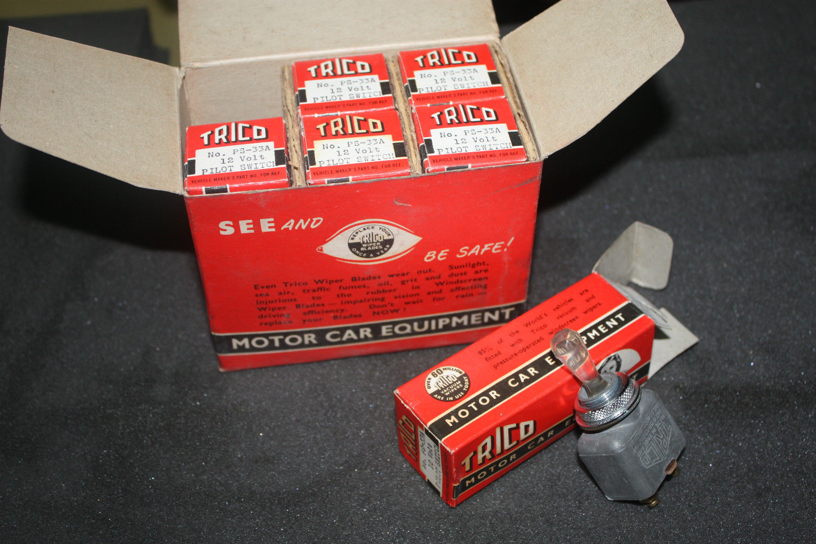
The PS-33A is used as a direction indicator switch. It has additional screw terminals for the festoon bulb at the bottom of the switch. It is not a direct replacement for the Overdrive switch PSG-4A.
Complete box with 6 pcs Trico PS-33A
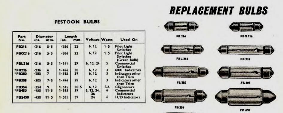
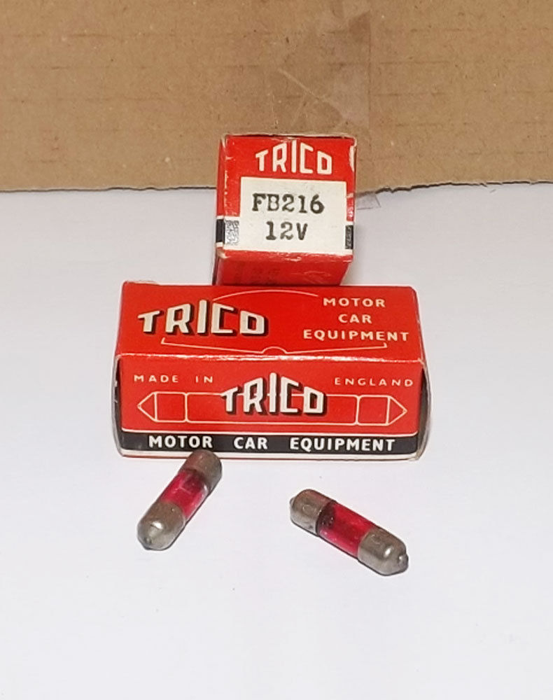
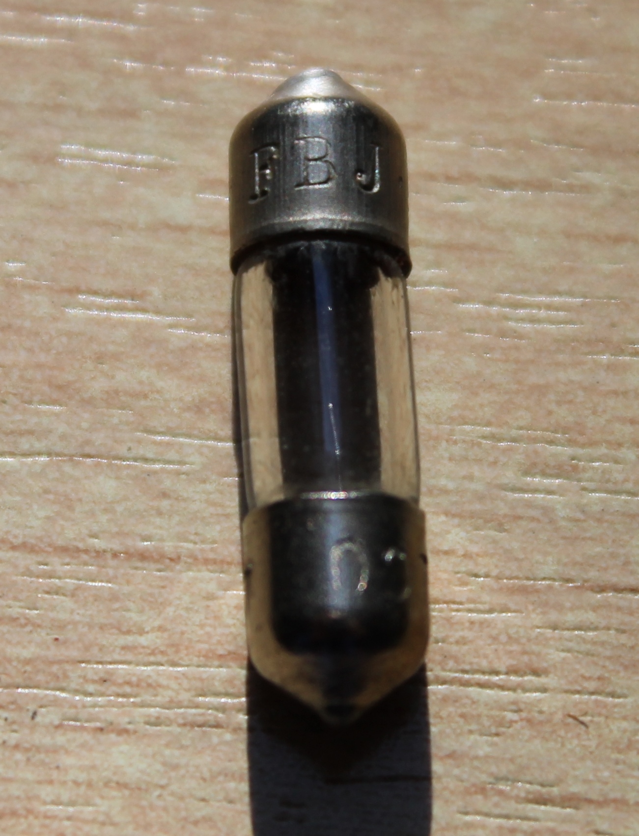
Trico “Festoon” bulbs
The bulb was of the “festoon” type and was supplied by Trico. There are 2 known bulb colours: red and green. The Trico part number for the built-in indicator bulb is FB216, which is a 12V 1.5W festoon green bulb of 22 mm length. Trico provided a large range of “festoon” bulbs: only the FB216 version was correct for the PS switches.
Green replacement bulbs are very hard to find. In Germany a similar bulb type is coded S6 (6 x 24 mm) 12 volt available in either 1.2 W or 2.0 W with S5.5 bulb contacts. The standard diameter of the original Trico bulb is 0.216” or 5.5 mm so the S6 version will fit. Sometimes available in green but 2W instead of 1.5 W (e.g. Scharnberger 25929).
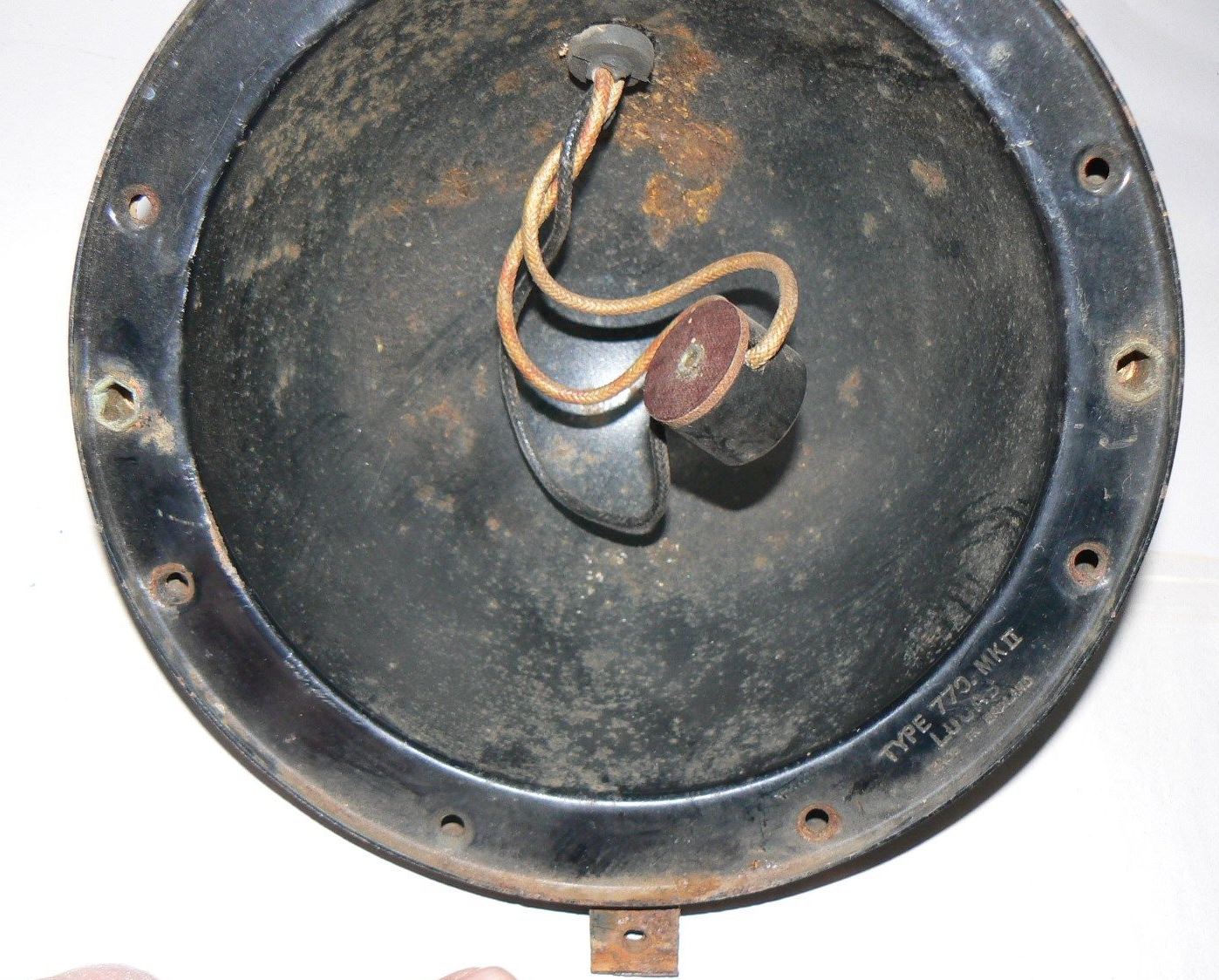
XK120s destined for the UK (“Home Market”) had the larger PF770 head lamps (7¾” or roughly 200 mm diameter) and used a dedicated LH and RH lamp per car of which one had a double filament and the other a single filament. XK120s for other countries (as far as legally allowed) had these PF770s with two double filaments lamps for both LH and RH.
All double filament lamps used Lucas Bulb Holder 554602 (double contact and 1½” or 38 mm in diameter) with 3 wires of suitable length and a rubber grommet. This assembly may have been initially made for Jaguar only. It had Jaguar part number 3581 and received Lucas part number 858543. The single filament head lamp of the early Home Market XK120s (Jaguar part number 3580) had Lucas assembly 858540 consisting of single contact Bulb Holder 554607 and only 2 wires of suitable length and a rubber grommet.
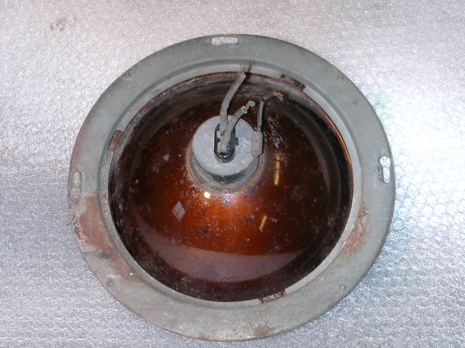
Bulb holder assy 858543 for the PF770 light unit (left). Note large lamp opening in the reflector (right)
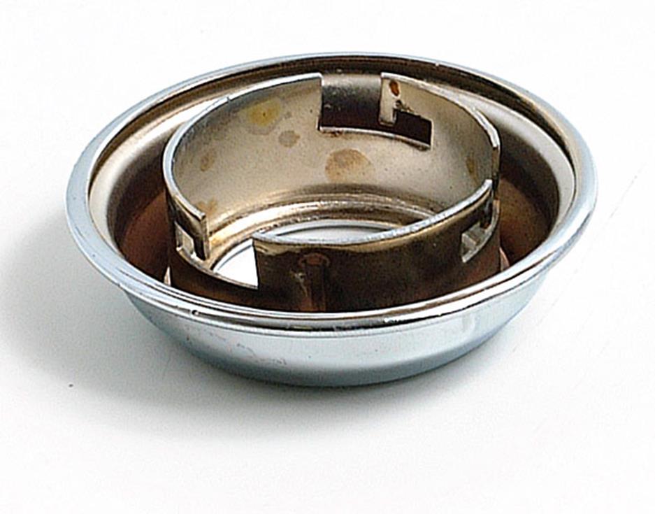
The reflector had a large opening, necessitating the use of a “Back shell assembly” or “Shell adaptor” (Lucas 553480) which in fact is a part of the reflector closing the gap between light unit and bulb holder.
Detail of Bulb holder assy 858543 Shell adaptor 553480 fits in reflector opening
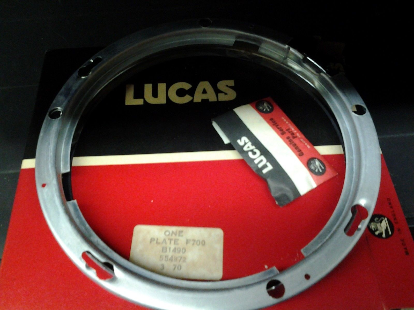
2. The “J 700” lamp range for XK140 and XK150
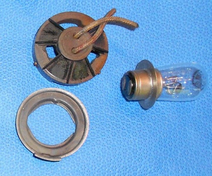
XKs with “J 700” lamps used Bulb Holder Lucas 554855 for the BPF bulb Lucas 404 (60/36 Watt). This bulb holder has 3 wires with a length of about 36” (90 cm) with a black plastic sleeve over these wires. Bulb holder 554855 fits within the round opening at the back of the reflector and has three “pins” that fit in the corresponding holes (see photo) in only one defined position (the so called lamp base “key”).
Bulb holder 554855 and Shell adaptor 554909 Larger reflector opening in J 700 light unit
The diameter of this Bulb Holder is somewhat larger than the diameter of the other light unit types. Like the PF770 lights, the J-700 uses a “Shell adaptor” (see red arrow below and photo above) to bridge the gap between reflector opening and BPF lamp base. The Jaguar number is 6670 and the Lucas number 554909.
Note: this item is also named “Back shell adaptor” which may lead to confusion. The black dome/bucket in which the light unit is housed is also called a Back Shell. Some sources use part number Jaguar 6670 or Lucas 555909 for this black enamelled back shell or bucket, but this is incorrect.
3. Export to USA and Canada: 3-pin “sealed beam” range for XK120, XK140, XK150
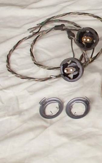
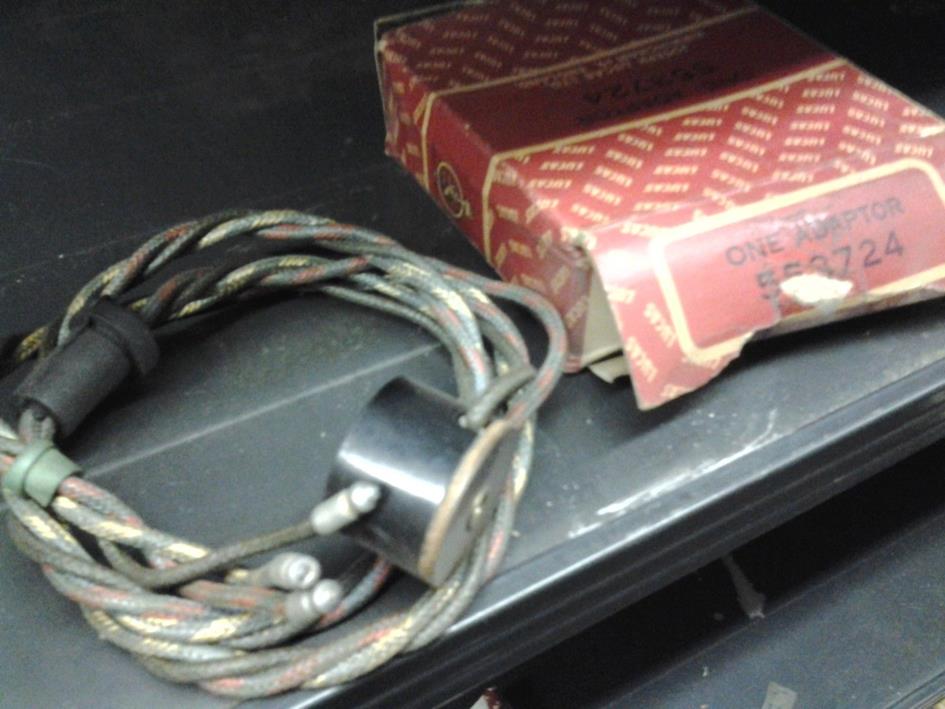
Since standardisation of vehicle lighting in USA and Canada was quite different from the European situation, “empty” head lamps (without a light unit and bulb) were supplied with XKs destined for North America. A special Bulb Holder / Adaptor with Jaguar part number 3454 (Lucas 553724) was used for the wiring harness, suitable for 3-pin US “sealed beam” bulbs. The Lucas adapter was a round construction in which the 3 connectors had been mounted. This version was used until July 1960.
Original bulb holder 553724 for North America Complete backshell & bulb holder for US sealed beam
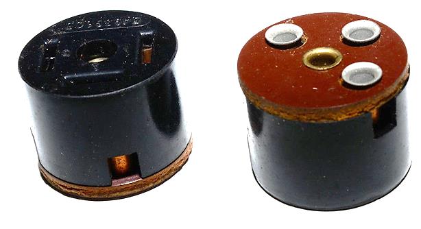
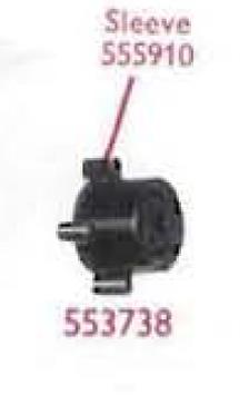
Later XK150s (from early July 1960 onwards) destined for North America had a different bulb holder with part number Jaguar 7764 and Lucas 553738 for 3-pin “sealed beam” head lamps, due to a change in the “USA Vehicles Lighting Regulations” (see also Jaguar Spares Bulletin Q17 dated November 1960). This is a bulb holder without any wires attached. There are two known versions of Lucas 553738:
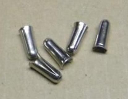
· The first version looks identical to the aforementioned bulb holder Lucas 553724 however with wire contacts at the rear, using 3 “Terminal Sleeves” Lucas 188818 for ⅜” stranded wire cores. This seems an “intermediate” solution, awaiting the arrival of a new moulded bulb holder.
· A second version with the wire contacts positioned on the outer rim of the bulb holder base-plate, using 3 “Terminal Sleeves” Lucas 555910 (which is a later version of the 188818 also for ⅜” stranded wire cores). This bulb holder or adaptor was used until the mid-70s for all (British Leyland) cars exported to N.A.
First 553738 type
Second version of 553738
4. The PF700 and F700 range for Europe for XK140 and XK150
Differentiation is made in two groups of countries:
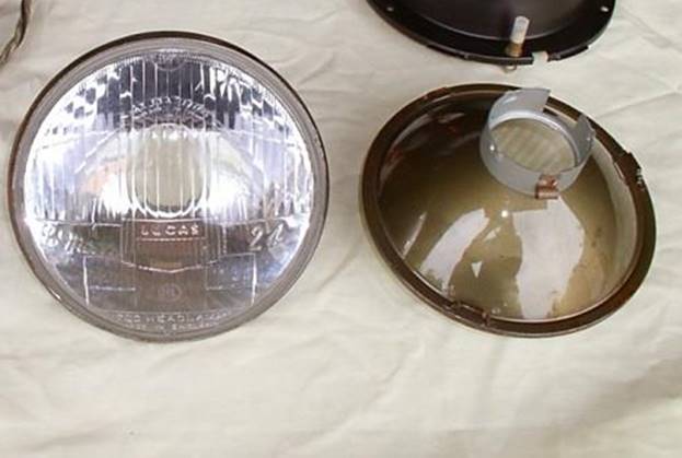
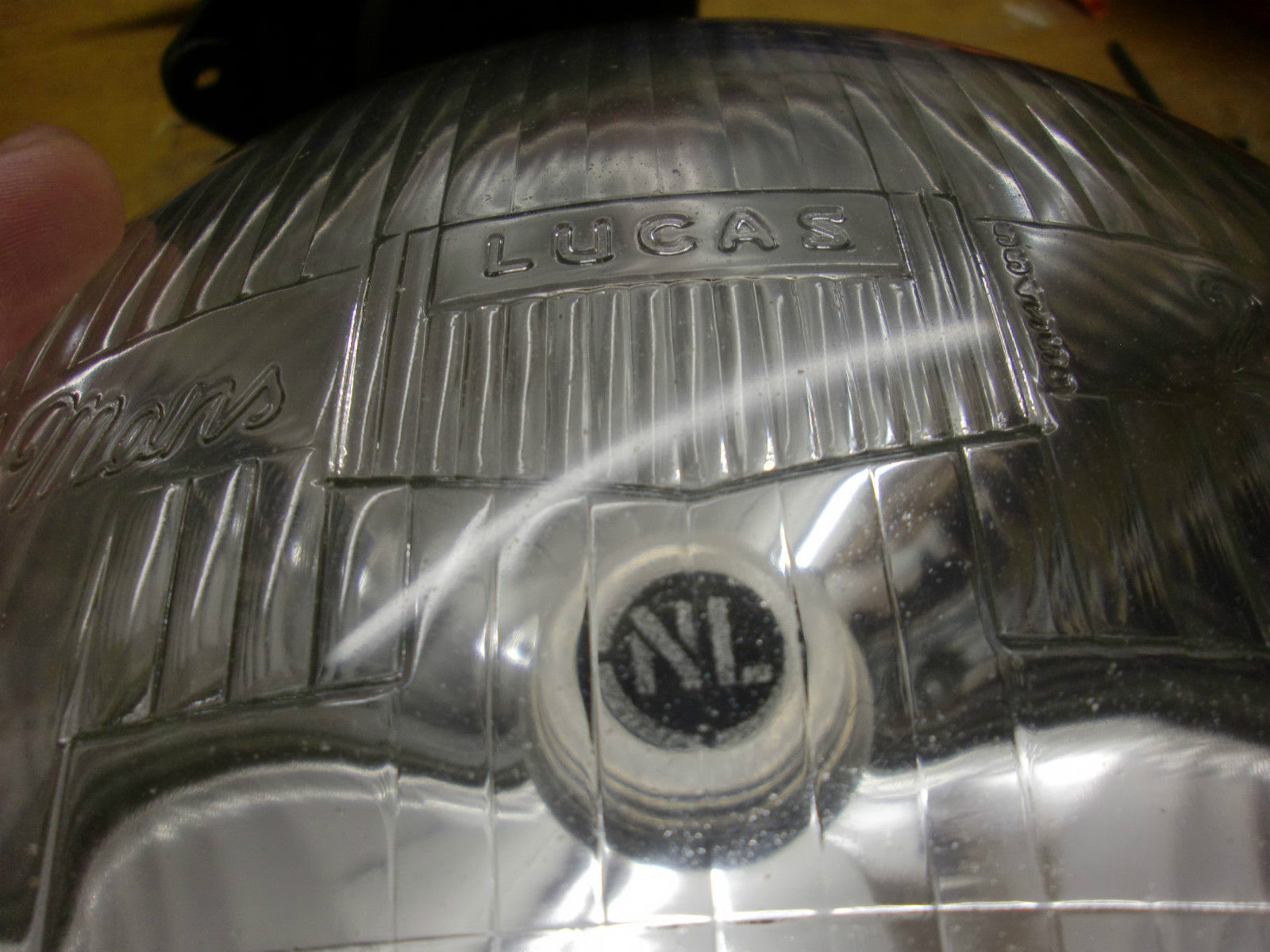
4.1. Continental Europe: “Le Mans 24” light unit for Switzerland, Holland, Norway, Sweden & Germany
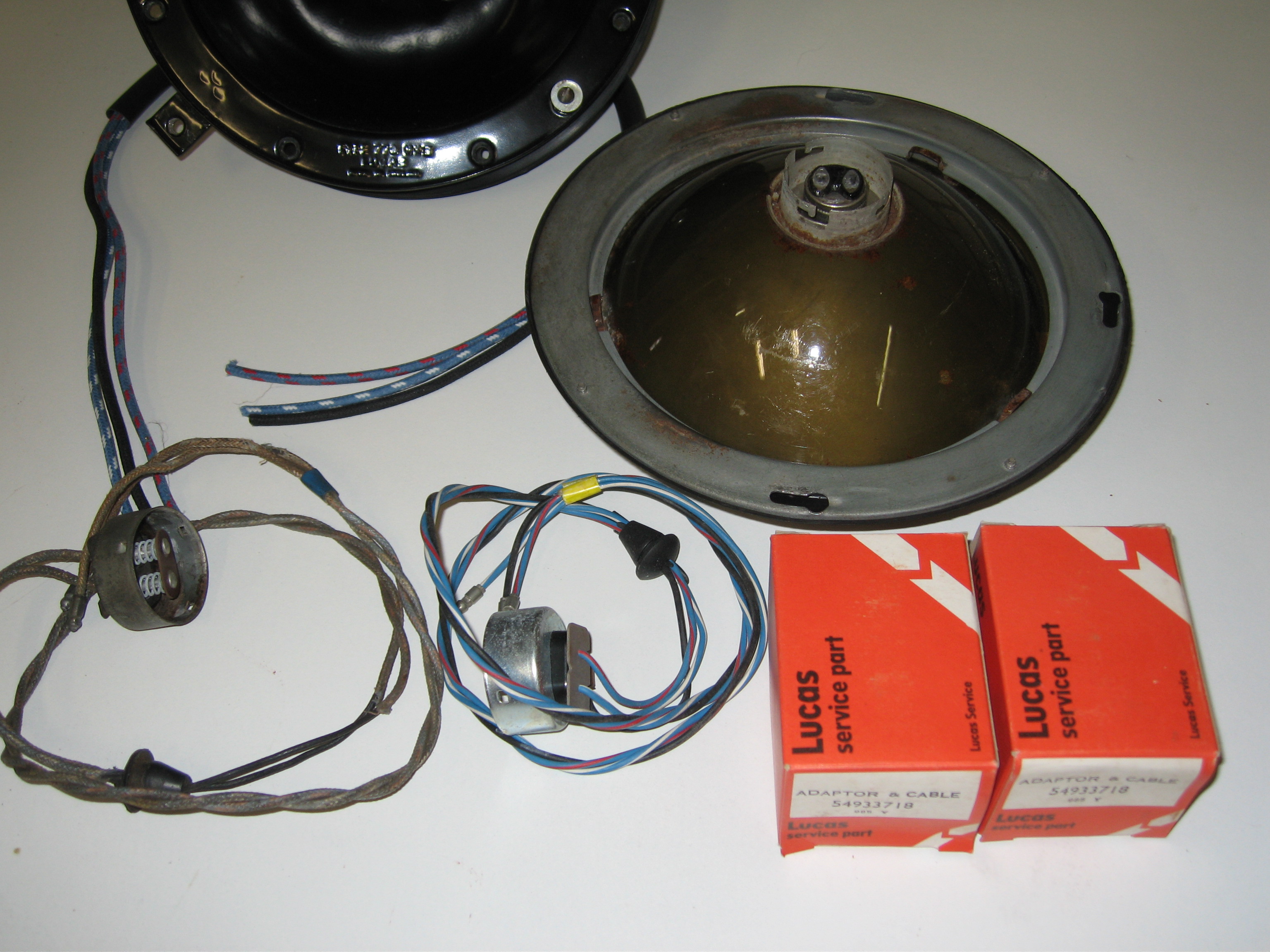
XKs for Switzerland and Holland had special head lamps (Lucas 51565A), as well as those for Norway, Sweden and Germany (Lucas 51564A). These were all based on the so-called “Le Mans 24” light unit (Lucas 554665) and therefore used the same 1½” bulb holder and headlamp wiring loom (Lucas 858543), although the BPF bulbs were different (Lucas 370 with 45/40 Watt for the first group and Lucas 350 with 35/35 Watt for the second group of countries).
Bulb holder Lucas 858543 is an assembly consisting of bulb holder 556402 combined with 3 wires of suitable length for its application and a rubber grommet. It has been widely used for various brands in the 1950’s on PF770, PF700, F700 and other light units. Bulb holder assembly 858543 is intended for light units with a dipped beam and has 3 wires, whereas Bulb holder assembly 858540 is intended for non-dip beams and this loom has therefore one wire less than the aforementioned version
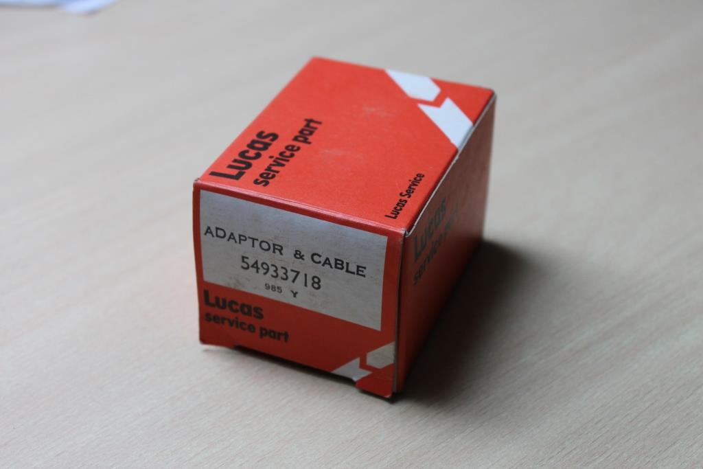
PF700 Le Mans headlights with Adaptor assy 858543 (left) and later replacement Lucas 54933718 (right)
4.2. Continental Europe: other countries with PF700 for XK140 and XK150
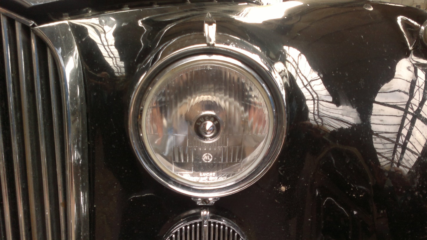
Some XK140 and XK150 versions intended for Continental Europe (except France, Switzerland, Holland, Norway, Sweden and Germany) used not a J700 but a PF700 type head lamp (51507A) with light unit Lucas part number 554917.
Lucas PF700 type 51507A with light unit 554917
The corresponding bulb holder is Lucas 554602 for the 45/40 Watt BPF lamps Lucas 370. This adaptor is in fact a bulb holder supplied without wires. For the installation of the earth wire to this bulb holder the “Terminal Sleeves” Lucas 188818 were supplied as well. The light unit of this PF700 is related to the “Le Mans 24” unit and has the same adaptor opening of 1½” or 38 mm .
5. XK120, XK140 and XK150 for France
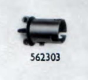
The French market required different Headlamps (Lucas 51563A) based on a 3-pin bulb BA21d lamp base (no BPF) and therefore also a different Bulb Holder / Adaptor (Lucas 562303). This solution was used over the entire existence of the XK range, although different light units have been applied.
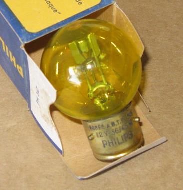
French bulb
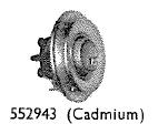
The French light unit for the XK140 and 150 is a special version (Lucas 555288) of the standard “Le Mans 24” unit (554665) that we described in chapter 4.1. As Lucas bulb holder 562303 for the P45t bulb has a smaller diameter than the BPF 370 bulb of the standard “Le Mans 24” version, an additional “Shell Adaptor for Bulb” with Jaguar part number 6527 and Lucas 555943 is required.
Special “french” Shell Adaptor Lucas 552943
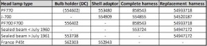
6. Survey of XK bulb holders, shell adaptors and replacements
The Bulb holder assembly Lucas 858543 has been replaced by Lucas 54933718 which is a generic replacement for various brands.
Can still be found…
7. Bulb holder adaptors
To use BPF lamps on US cars (or European cars with a “non-BPF” headlamp loom) an adaptor exists that fits in the existing Lucas 553724 loom or the later Lucas 553738 bulb holder. This Adaptor has Lucas part number 554691
Front and rear of Lucas Adaptor 554691, converting e.g. US headlights looms to BPF bulbs
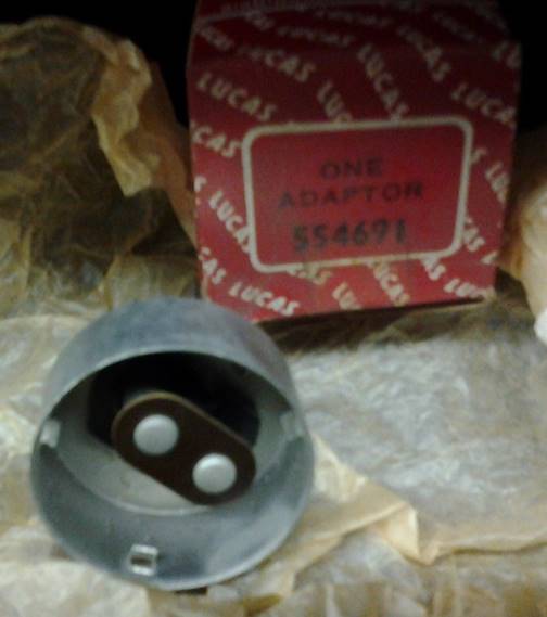
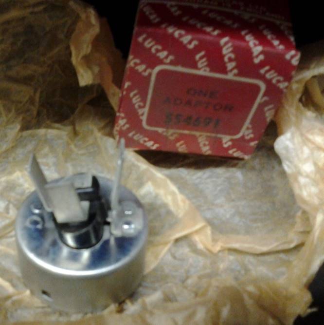
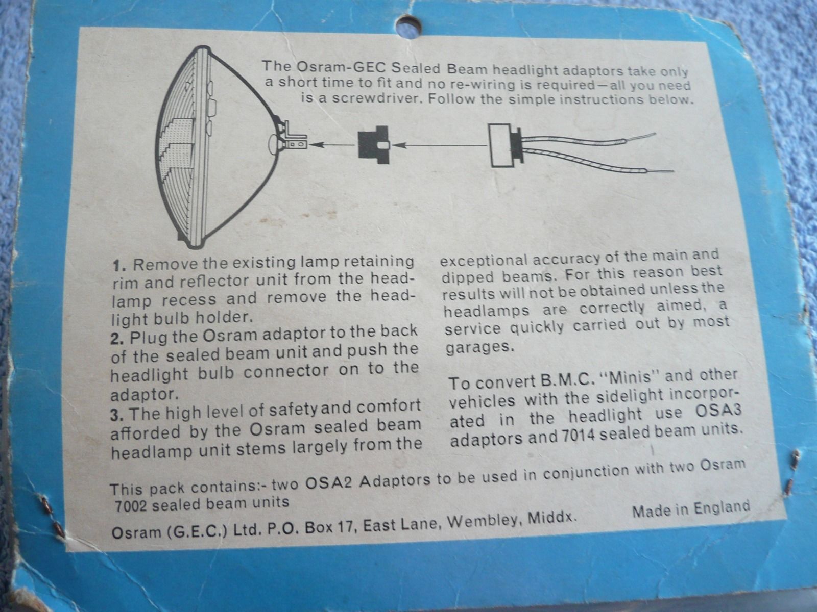
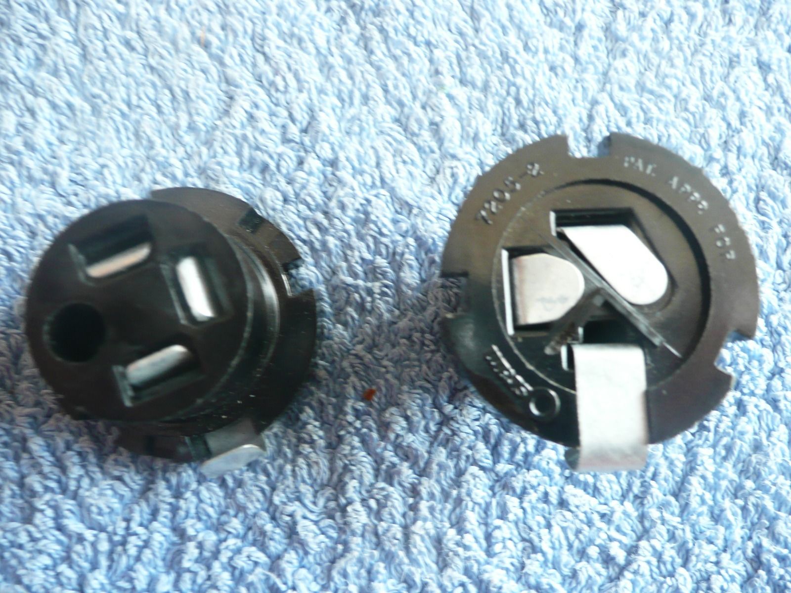
In the 1960s Sealed Beam headlamps were introduced in Europe; all sealed beams had the 3 pin connection whereas most British cars still had a BPF bulb holder. To facilitate the conversion to sealed beam lamps special adaptors were made with a 3 pin connection on one side and the BPF connection on the other side, fiting in the standard BPF headlamp harness with bulb holder. Note that these adaptors were also supplied by the (in those days British company) Osram-GEC in an attempt to increase the sales of these sealed beams. This is of course also a fine solution for British car owners in the USA who want to convert an existing BPF harness.
Adaptor for converting BPF harness to Sealed Beam lamps
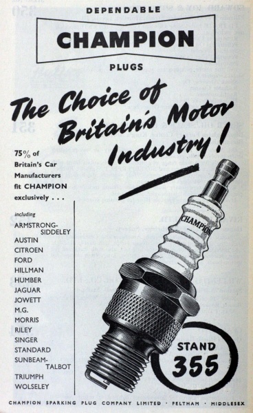
From 1934 onwards Jaguar used Champion spark plugs for their pre-war (SS) engines. This may also have influenced them to source spark plug caps (or HT cable terminals) from Champion after the war.
Advertisement 1951, mentiones Jaguar
History of Champion in UK
Champion started it spark plug activities in 1908 in Boston, USA and then moved to Toledo, Ohio, USA in 1910. In 1920 Champion moved across the Atlantic and established the Champion Sparking Plug Company Ltd. in England with their offices at 83, Pall Mall, London. Their UK industrial facilities were at Hatton Cross, Feltham, Middlesex (near London) and stayed there until it had to move due to the extension of Heathrow Airport in 1968. Thereafter the Champion Spark Plug Company operated an automotive components factory on Arrowe Brook Road, Upton near Liverpool employing at one time over 1,000 people. It was closed in 2006 and the production was transferred to Italy.
Early spark plug terminals: Jaguar C404
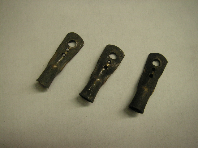
Pre-war and first post-war models like the Jaguar MK IV and MK V used an uninsulated horizontally positioned terminal made of tempered (tinned) brass (Jaguar part number C404), which was secured by a nut on the threaded end of the spark plug. The manufacturer of these terminals is unknown.
Early spark plug terminal C404 (Courtesy Rob Reilly)
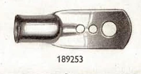
Lucas HT terminal end 189253
Lucas HT terminal end 189253 for 7 mm cable seems identical to Jaguar C404 and we may conclude that these were supplied by Lucas.
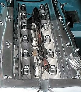
Note that all XK engines as used for the XK120, 140 and 150 had “straight” spark plug caps, apart perhaps from some early (experimental) engines that had horizontal connections for the HT wires.
Jaguar C1575: uninsulated straight terminal
The early Jaguar XK 120 (up to engine number W6372; late October 1952) had a spark plug terminal Jaguar part number C1575, which is in fact an uninsulated straight metal sleeve connected to the HT wire. This method of fastening the HT cable to the spark plug terminal is different from all later systems: the copper core of the HT cable was mechanically connected to the brass sleeve that fits over the spark plug end.
C1575 uninsulated straight terminal
Example of an uninsulated straight spark plug terminal
Up to November 1952 XK 120’s had a distributor cap (Lucas 415708) with horizontal cable outlets: the HT leads entered through holes on the side and had a screw on the inside that fastens down on the leads. So the early HT cables had a metal sleeve at one end and nothing at the other end.
Lucas 415708 for early XK 120
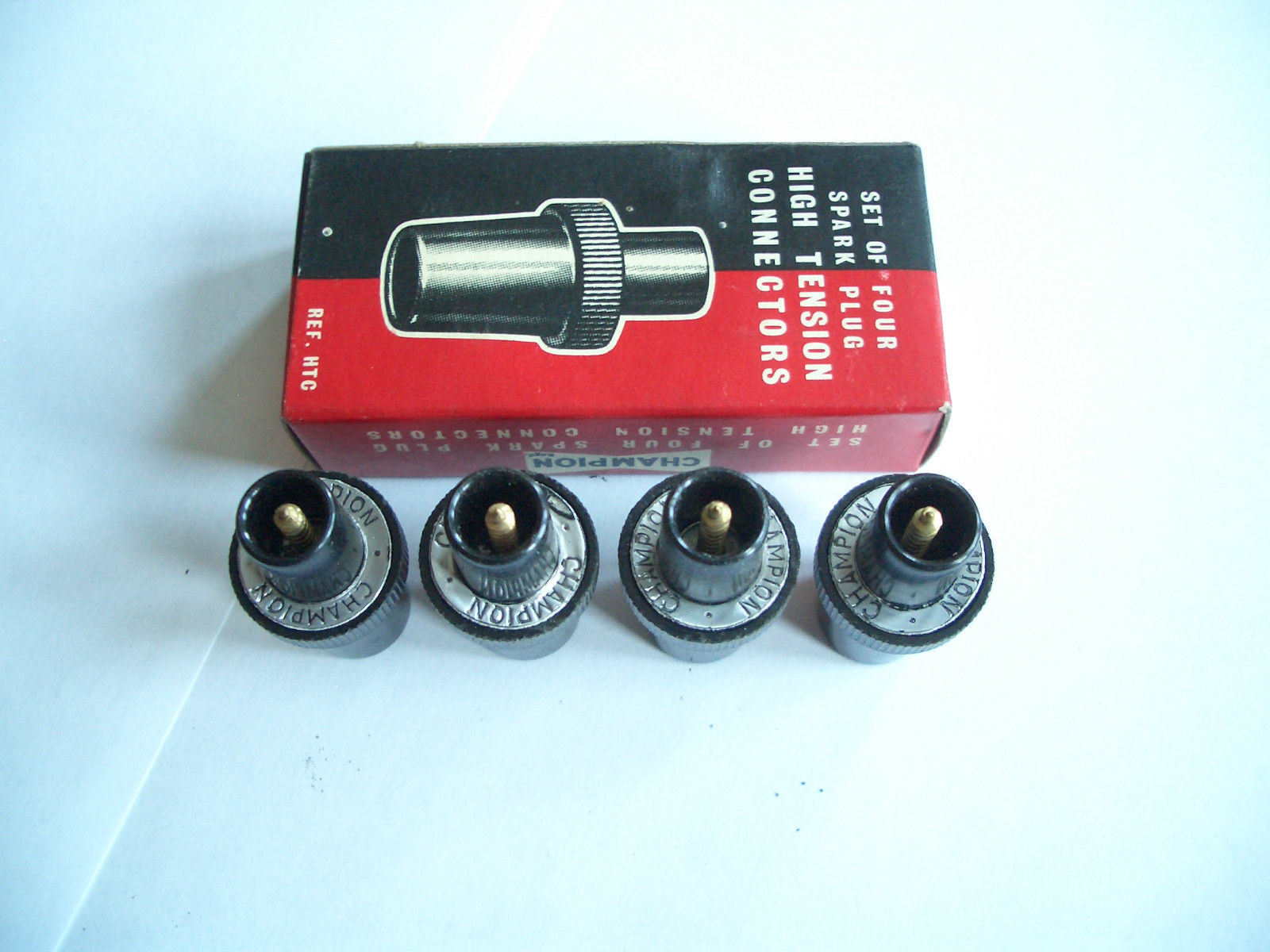
Jaguar C5479: Champion HTC cap
From late October 1952 onwards the XK120 received a spark plug cap made by (or made for) Champion. Jaguar changed over to an insulated (Bakelite) spark plug cap type replacing the bare metal C1575. The original early version (that we know now as the Champion HTC type) had tiny embossed letters on the rim in the middle: “Champion Made in England”. They have an internal, fixed screw tip and are screwed into the centre core of the HT wire ends.
Text “Champion Made in England”
This Champion plug cap was used on the later XK120, XK140 and XK150, unless a suppressor plug cap was required (see hereafter).
Lucas 407043 for later XK 120
About the same moment the fastening system with “moulded nut and split-washer” for the HT wires to the distributor cap was introduced (late November 1952) when the XK changed over to a distributor cap with vertical entry (Lucas 407043) and a different routing for the HT cables. So both ends of the HT cable got new “terminals”.
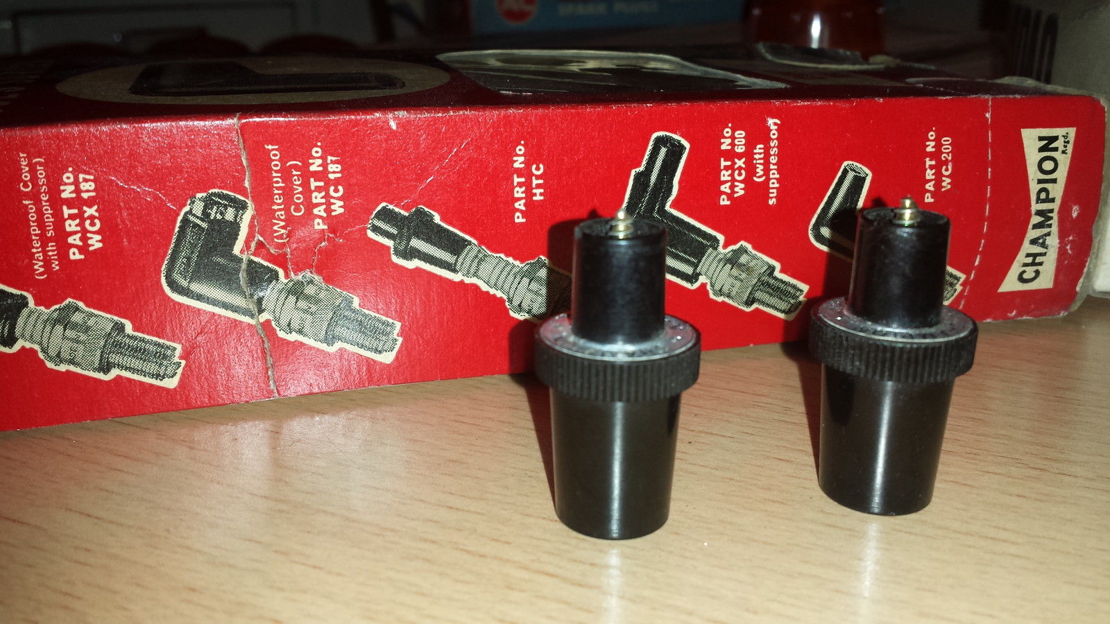
Later Champion HTC 2 plug caps (replacement for original)
Difference between original and new HTC 2
A new HTC version was introduced in the 70’s. These are slightly larger in diameter, have a wider knurled ring and the embossing (Made in England) has been replaced by an initially grey and later red printed paper ring with two times “Champion” on it. Apart from the missing embossing, the newer versions can be easily recognised as the black housing has less taper at the plug end, whereas the other end has almost no taper at all. Both are of the same length but the pin that screws into the HT Cable core protrudes further in case of the newer versions (see photo above).
As mentioned above, there are two basic productcversions: the original and the replacement version. The latter can be divided in the initial “Grey ring” version followed by the “Red ring” version. The difference is also shown in the boxes that belong to two later replacement versions:
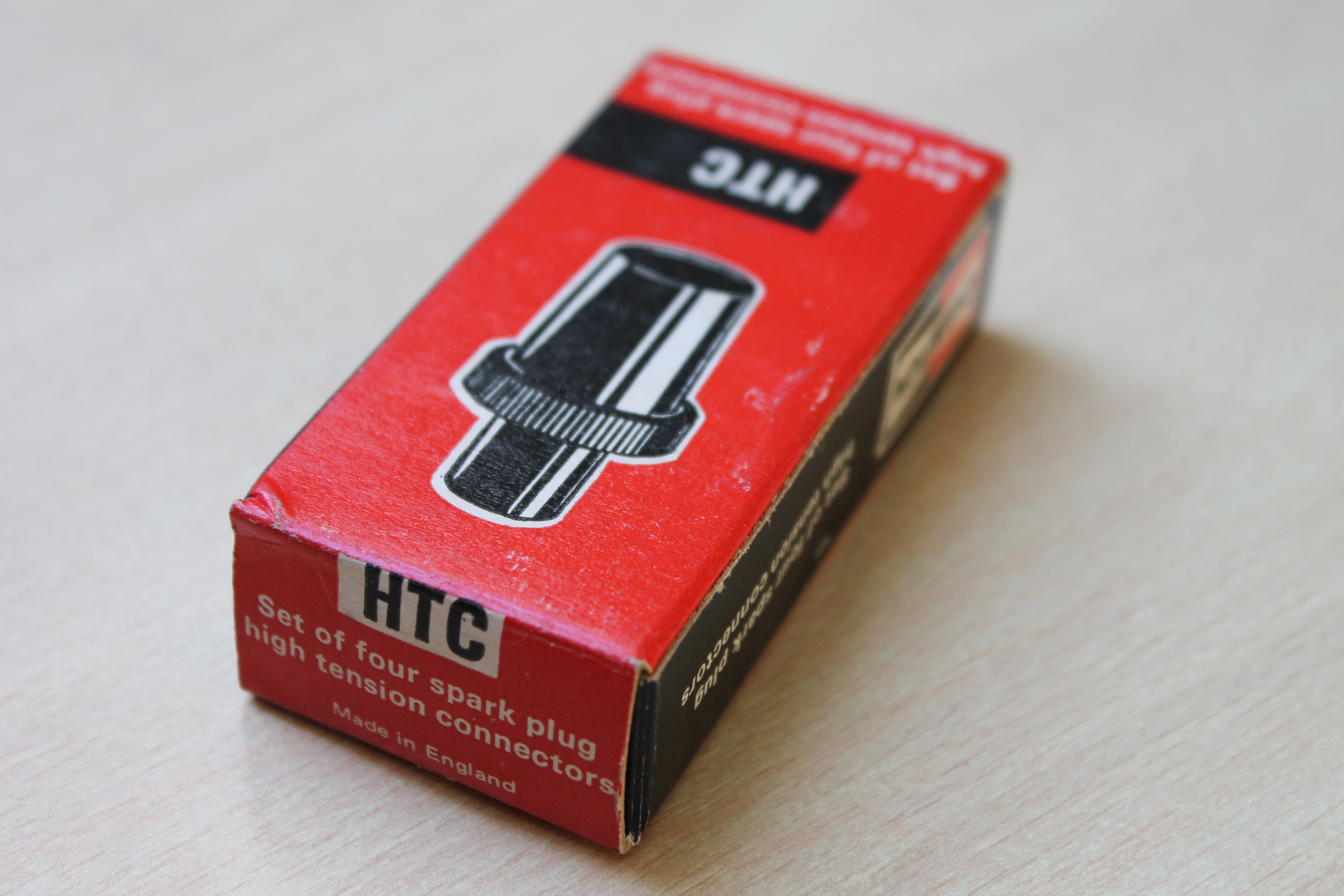
“Grey paper ring” box with description “REF. HTC” or “Part No. HTC”
Early versions had a Grey paper ring and can be recognized by the “slotted” screw for connecting the cable core, that can be seen on the inside of the metal part that snaps over the spark plug. Note the text on the box “spark plug high tension connectors Ref. HTC”. We may conclude from this that the early “grey ring” version was still called HTC instead of HTC2.
Box for later “Red paper ring” versions with model number “HTC”
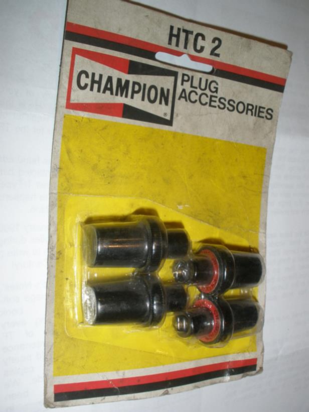
Blister with “HTC-2” spark plug caps
Note that the “Red paper ring” version is not named HTC-2 on the box. These later Red paper ring versions can be recognized by the “crosshead” screw on the inside of the metal part that snaps over the spark plug.
Alternative Champion HTC cap with fixing screw
Another Champion “HTC cap type” that occasionally comes for sale, has a fixed, internal brass piece into which the exposed lead wire end is fitted and then held in place with a set screw. This version was applied by BMC (part number AEC 388). The mould used for the Bakelite housing is apparently the same as for the initial HTC cap as the embossing (Made in England) is identical.
HTC with screw
As far as we know this version was never used by Jaguar.
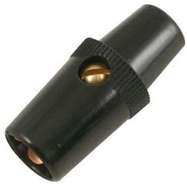
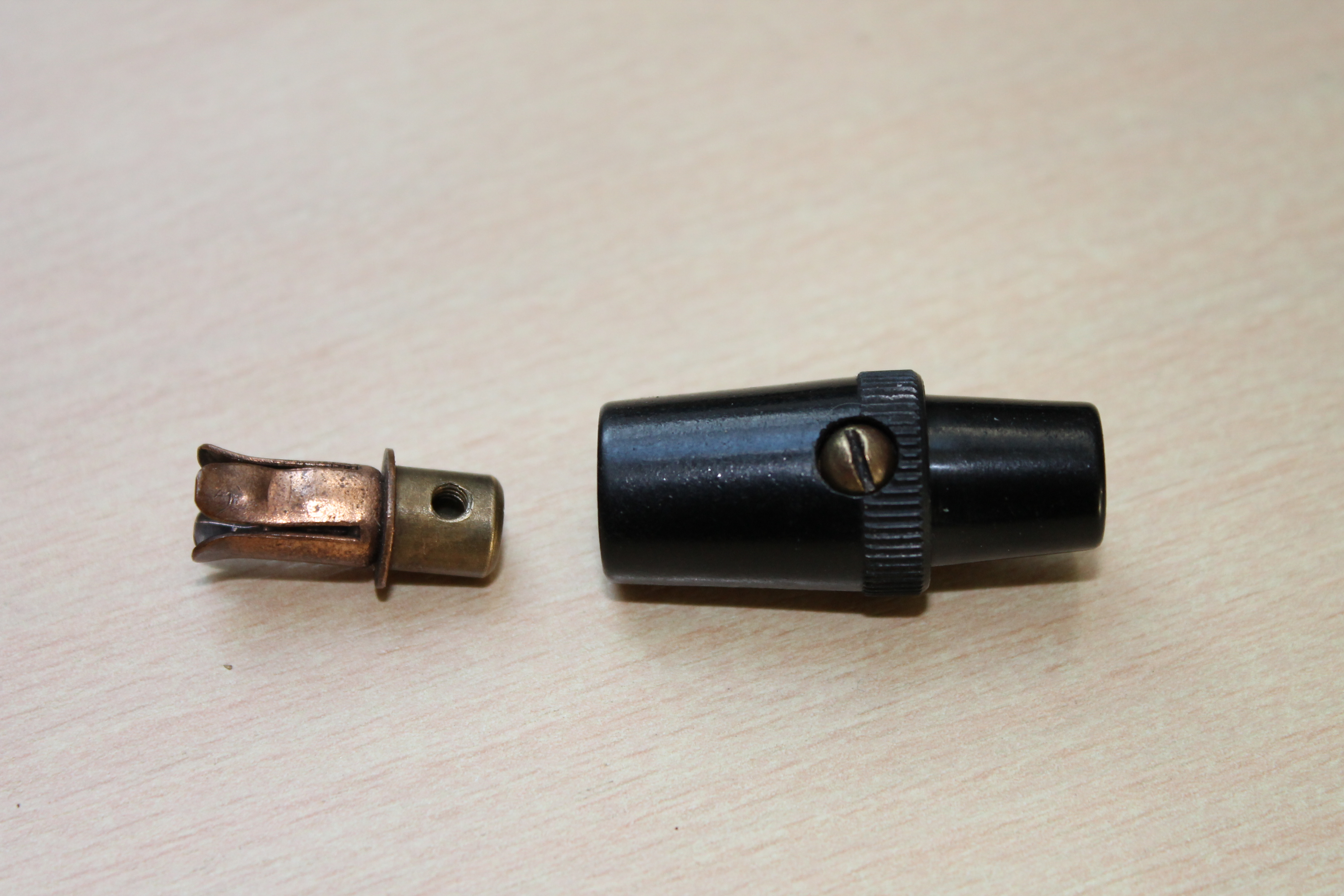
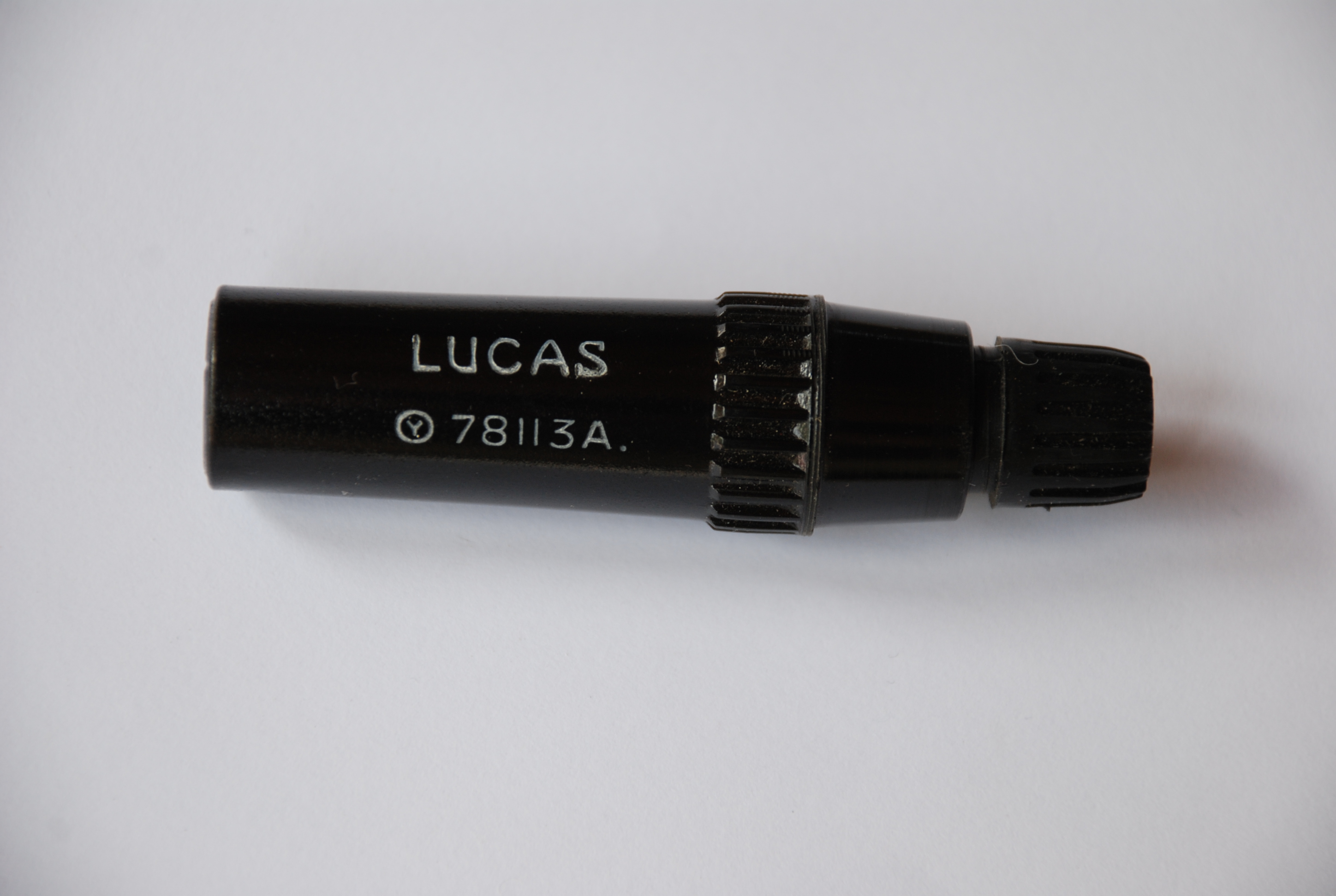
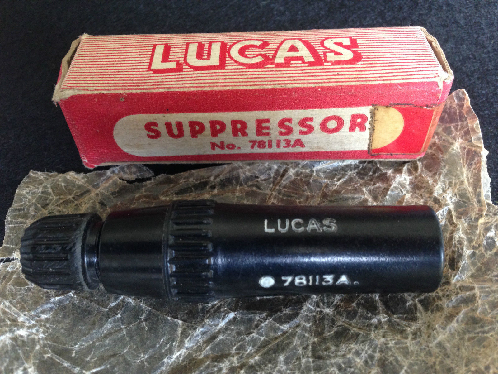
Jaguar C.8306 Lucas 78113A spark plug suppressor cap
With the arrival of TV in the early 1950’s in the UK (and elsewhere of course) the need for a “suppressor” version arose. Initially the Lucas type WS5 spark plug cap could be installed as “optional” and wasn’t applied as the “standard” plug cap.
Service Bulletin SB131 (dated August 1953) however had the following information: Note that all Home Market and Home leave cars are now fitted with ignition suppressors. So we may conclude from this that the majority of the exported cars still had the Champion HTC spark plug cap installed.
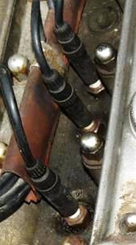
The 1960 XK150 SPC clearly states that the C.8306 spark plug suppressor cap was now installed on all Export versions. The exact implementation date is as yet unknown, but probably in the period 1957 – 1959.
Suppressor Lucas 78113A (photo: Roger Payne) Lucas 78113A has resistance of about 18 kΩ
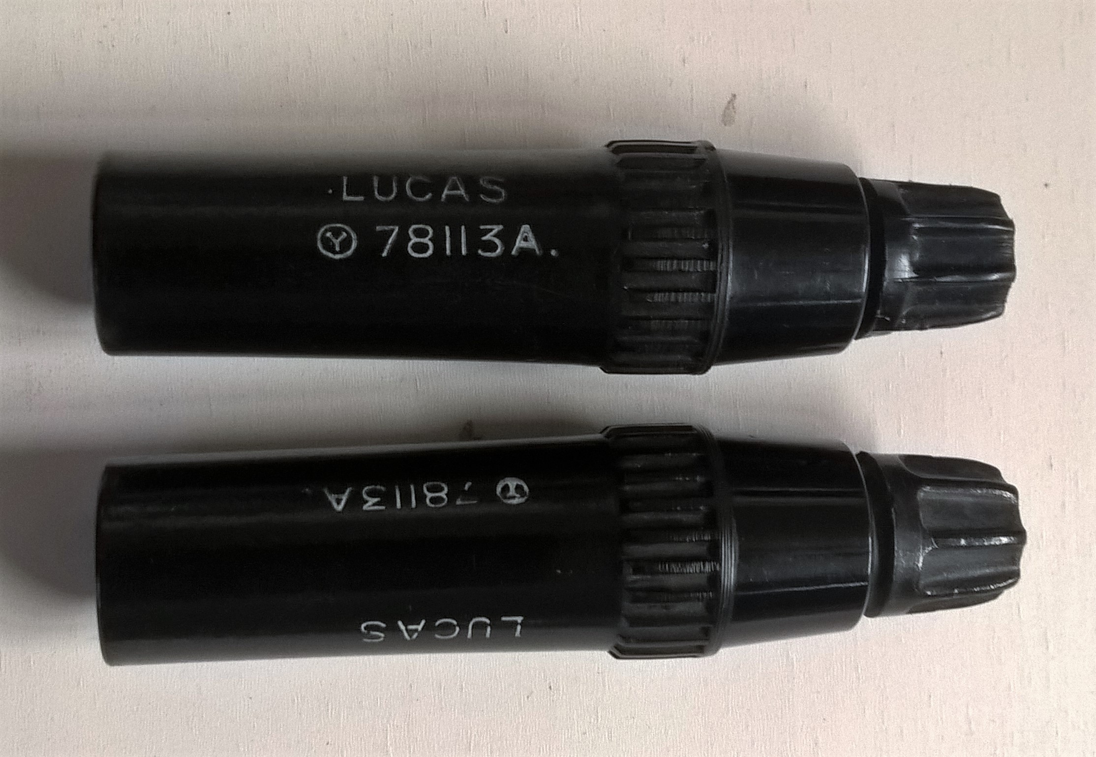
Lucas suppressor 78113A in original box Two versions of 78113A with text 180 degree rotated
The resistance of this Lucas suppressor is about 18 kΩ. The HT lead connection is similar to the distributor cap installation with “moulded nut and split washer”. Note that there are two different versions of this suppressor whereby the text has been rotated 180 degrees. The part number itself did not change. The photo above left is identical to the bottom version on the photo right and is probably the first generation: the font is smaller and it smells like “Bakelite”.
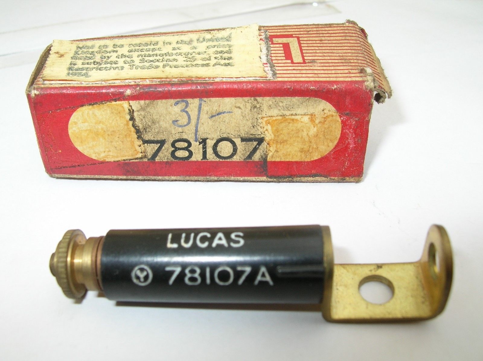
For older cars with an uninsulated brass terminal secured by a nut on the threaded end of the spark plug, Lucas introduced a special suppressor 78107A . After the existing nut has been removed, this suppressor is positioned on the spark plug (either horizontally or vertically) and the nut is placed back. The brass terminal of the plug cable is attached to the other end of the suppressor.
Lucas suppressor 78107A for earlier cars
Other types of suppressors
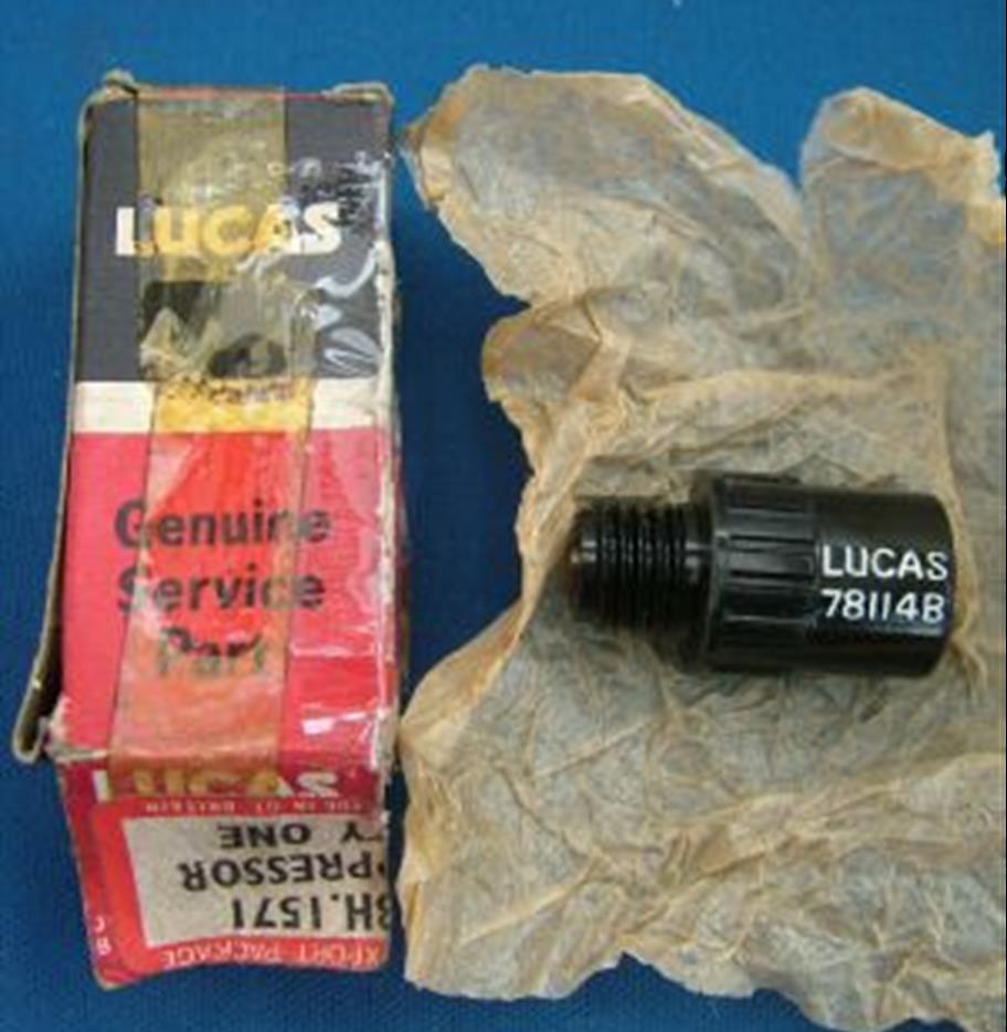
As mentioned above, most XK’s left the factory with Champion plug caps without suppressor. The XK120 Spare Parts Catalogue, however, refers to Suppressor C8046 installed on the Distributor Cap of all Home Market XK120s in addition to the Plug Suppressors C8306. Reference is made of Suppressor C8046 (Lucas 78114A) described as an alternative solution for the Lucas 78113A spark plug suppressor cap . This single suppressor, with a resistance of about 10 to 15 k Ω, is positioned in the centre connection of the distributor cap. In this way the spark from the coil is suppressed before it enters the distributor cap. A warning is given not to install this suppressor in the connector of the ignition coil: “If fitted to the coil (instead of the distributor cap) there will be a ¼”gap causing ignition failures”
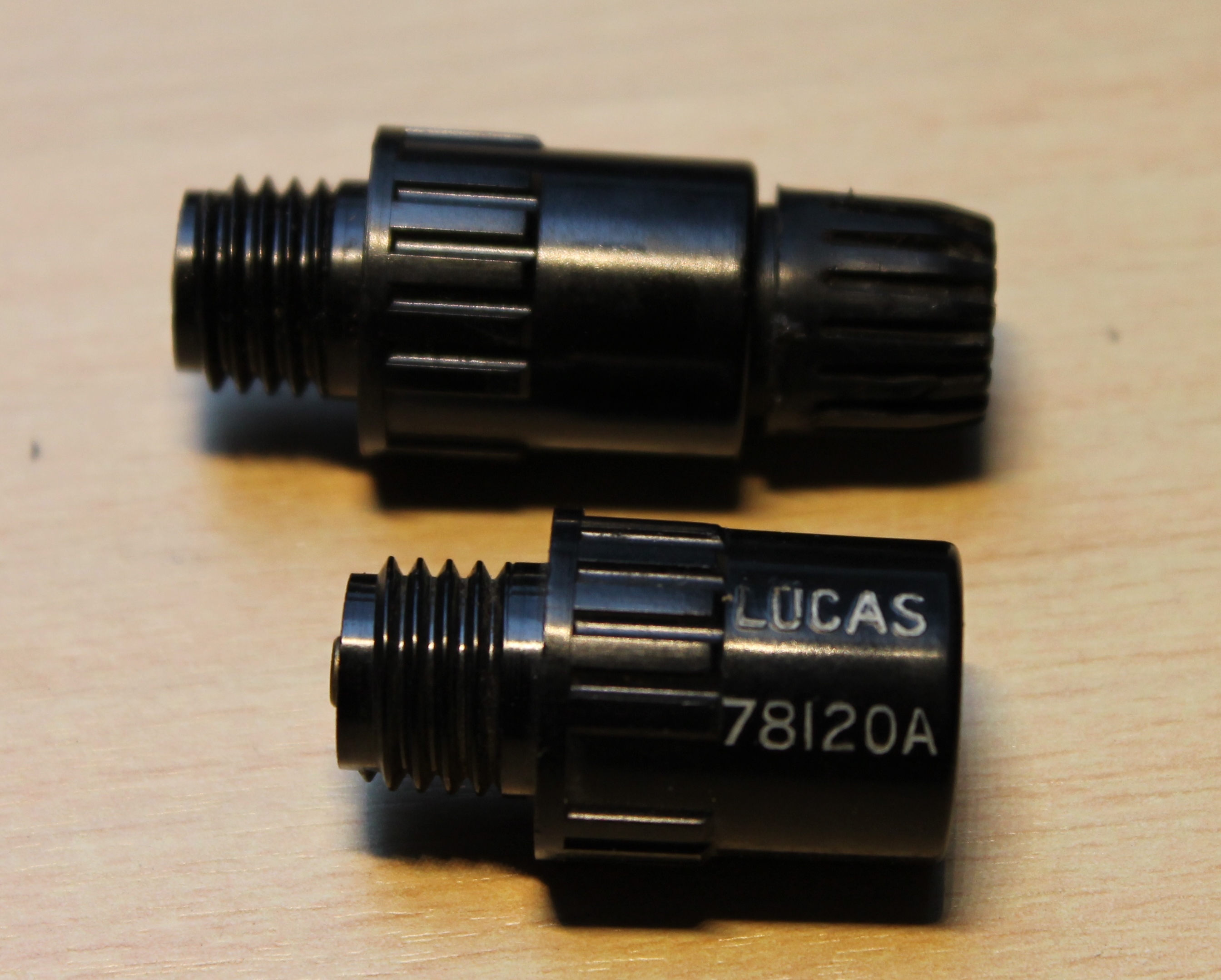
A second version of this distributor cap mounted suppressor is Lucas 78120A which is identical to Lucas 78114A however with a lower resistance of 6.3 k Ω.
Suppressor C8046 for centre contact distributor cap.
Identical cap-mounted suppressors (but also many other suppressor types) have been manufactured by Erie Resistor Ltd of Great Yarmounth (UK). The Erie D8 is an exact copy of the Lucas 78120A suppressor which may lead to the conclusion that Erie actually manufactured these for Lucas.
Lucas 78120A with identical Erie D8 (with nut) above
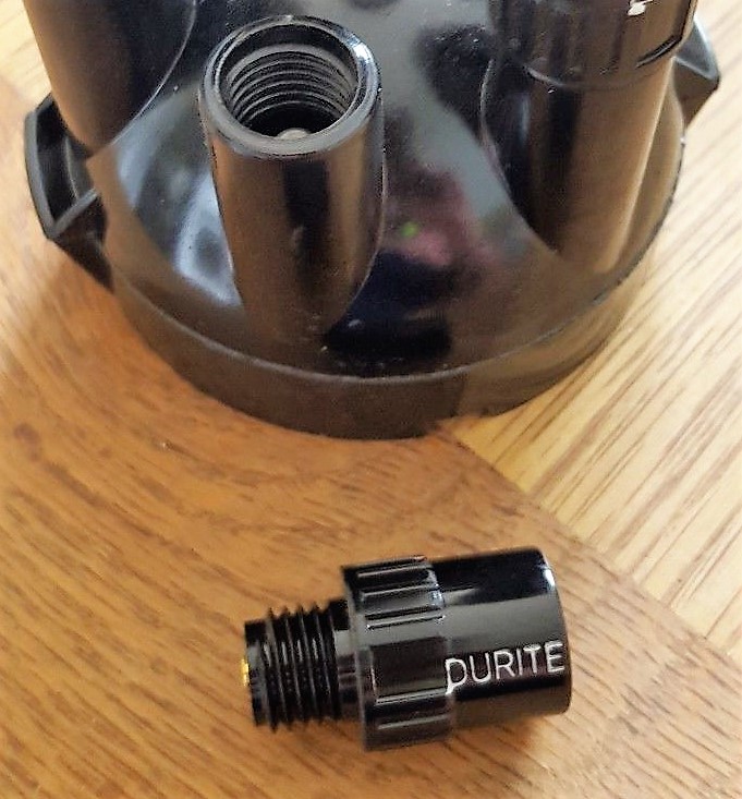
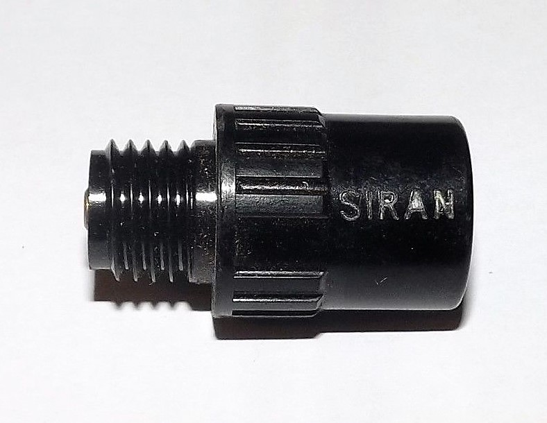
There were a number of other companies supplying the same suppressor, like Durite and SIRAN. Durite was a British manufacturer of automotive electrical equipment. SIRAN Accessories was a 1960’s British company based in Hove, known for its car instruments and switches. Resistance values are unknown.
Suppressor supplied by Durite Same suppressor now branded SIRAN
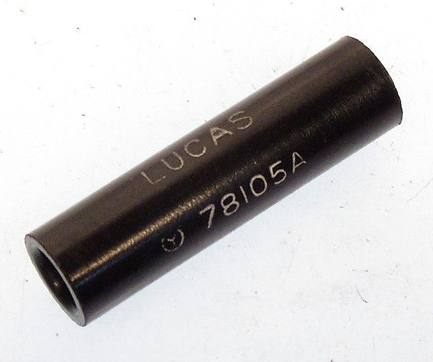
Another version was the “cable type of suppressor” as e.g. Lucas 78105A. This type is normally placed in the cable from HT Coil to Distributor cap and is screwed in the copper core of the HT lead. But it is sometimes used in every spark plug lead.
Lucas cable type suppressor 78105A
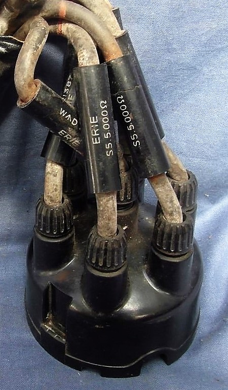
The Erie Resistor Lid. also provided a cable suppressor (probabale code number WAD.1738) with 5000 Ω resistance. An example is shown below with a suppressor in all 6 HT leads.
Erie Cable type suppressor of 5 kΩ
In May 1957 Jaguar Saloons received a new DMBZ distributor with a distributor cap with “built-in suppressor”. Reference is made of Service Bulletin No. 212 of May 1957 which states: ” Note that the DMBZ type of distributor fitted to the above models incorporates an inbuilt suppressor. The suppressor normally fitted in the centre terminal post of the distributor is therefore unnecessary and must not be fitted.” The centre terminal post suppressor as refered to is the above described Lucas 78114A (or Lucas 78120A version).
Although the export share of British sports cars going to the USA was much bigger than those heading for continental Europe, Lucas acknowledged in the early 50’s the necessity to come with an improved, highly efficient light unit for (fast) driving on the (European) continent. Lucas opted for “vertical dipping” making use of British Pre Focus (BPF) bulbs.
Given the formidable British racing successes in Le Mans, the PR department of Lucas decided that this headlamp series would be called “Le Mans 24”. Although some sources indicate that these head lamps had been specially developed by Lucas for racing at Le Mans, this is factually incorrect. The assignment for the Lucas development group was much more complicated because Lucas management wanted a very efficient head lamp system that could fulfil the legal requirements for road use in different (continental) European countries and that could be formally approved for those countries. Remember this was far before any form of European cooperation and legal requirements differed per country, often based on national laws that had been developed per country in “splendid isolation”.
The legal requirements for headlamps in the USA were totally different (and partially still are today): the “Le Mans 24” lamp was never intended to become an alternative for the USA. We will not enter here into a formal comparison of the legal requirements for the various continents and countries. We will however emphasis the requirements in some European countries that later formally approved the “Le Mans 24” headlamps, often in combination with the initial type approval of a car for that particular country.
Lucas “Le Mans 24” for XK 140
Jaguar was a technological forerunner in general and the first company to introduce the “Lucas Le Mans 24” on a production car, destined for Continental Europe: the Jaguar Mk VII carried the Le Mans 24 headlamp unit with Lucas type number 51472A and 51478A from 1952 onwards.
Vertical dipping
Traditionally European manufacturers created a main and dipped beam from a single bulb by introducing two filaments along the axis of the (parabolic) reflector. The high beam filament is always in the focal point of the reflector whereas the dipped beam filament is somewhat “out of focus”: in most cases about 10 mm to the front and 3 mm above the axis. European (continental, thus excluding Great Britain) legal requirements include a sharp cut-off beam pattern which is normally secured by a (cup-shaped) shield below the dipped beam filament which prevents that light would be reflected above the horizon. The bulb has a fixed position in the headlamp securing that the shield is always in the correct place below the filament. There are also other versions than vertical dipping available like RH and LH dipping, but they will not be discussed here.
Also note that in 1956 most continental European countries (again excluding GB) agreed to a new beam pattern in which the beam at the RH (or “passenger side”) of the light unit has been lifted 15 degrees: the typical arrangement that later became the EU standard and basically is still valid today. The Lucas “Le Mans 24” light unit does not fulfil this 1956 standard as its beam pattern has a (very sharp) cut-off over the entire width of the beam. Fortunately in most EU countries the legal requirements have been made in such a way that headlamp requirements contain a mandatory element for the sharp cut-off aspects, with the later (1956) addition that if there is a 15 degree lifted part in the beam, this has to fulfil a number of specific requirements. This implies that in most EU countries that had the sharp cut-off dipped beam pattern standardized before 1956, the “Le Mans 24” light unit would/should be accepted when offered for initial type approval or periodical testing.
Different types of Le Mans 24 light units
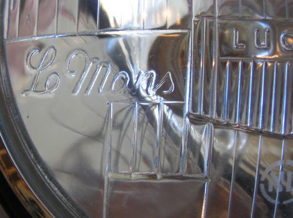
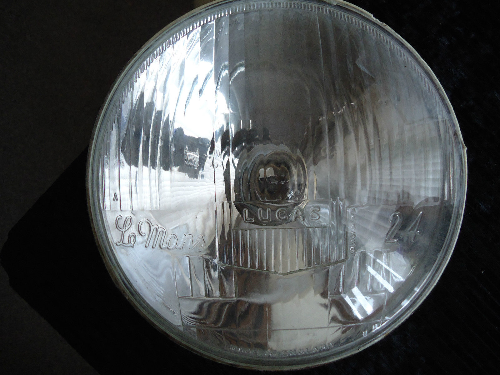
The most common version of the Le Mans 24 light unit is Lucas part number 554665 for use with BPF bulbs with lamp base P22d36.
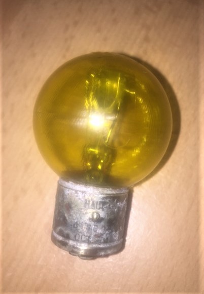
Lucas BPF bulb 350 and 370 with base P22d36 French 3 pin bulb with base BA21d branded Marchall
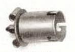
France was a completely different case with their legal requirement of April 1937 to have yellow headlights in combination with a 3 pin lamp with base BA21d. This was a 36/45W bulb with a 40 mm globe-shaped yellow glass envelope. This bulb type was not manufactured by Lucas (nor by their UK bulb suppliers). Instead Lucas offered an adaptor/bulb holder Lucas part number 562303 to accept BA21d bulbs.
Lucas bulb holder for BA21d Lucas “Shell Adaptor” with bulbholder positioned
From about 1954 Lucas offered a 3 pin BA21d version of the “Le Mans 24” light unit intended for France. The first introduced version was a light unit with Lucas part number 554615. This has not been used by Jaguar (but Aston Martin and Bristol did use this version for Export to France in 1954). This first light unit was succeeded by a second version Lucas part number 555288 which was used by Jaguar for Export to France.
Both the 554615 and 555288 light unit have a larger opening at the back of the reflector (over 40 mm in diameter because of the 40 mm globe-shaped glass of the French bulb) whereas the BPF has an opening of about 22 mm. This French system uses a “Shell adaptor” (Lucas 552943) which is a ring to close the gap between the larger reflector opening and the smaller outer diameter of Lucas bulb holder 562303. The Shell adaptor 552943 was delivered complete with Bulb holder 562303 (as in the above picture).
Lucas PF700EF light unit; part number 554288
The French Bulb holder and Shell adaptor combination also had to compensate the lamp centre length difference of the BPF and the 3 pin BA21d bulbs (LCL: distance from centre of filament to bulb base).
Survey of “Le Mans 24” light units
So resuming we have three different light units, all branded “Le Mans 24”:
Lucas part number 554615 using 3 pin BA21d bulb for France
This is a special reflector unit with a different mounting of the bulb (adaptor) using two clips (in stead of the bajonet fitting of the other Le mans 24 reflector units). The front glass had a special mark reading “Agréée AB-TP No 457” placed in a dashed rectangle. This is a French homologation mark for approved headlights fulfilling the French requirements as laid down in 1930. The bulb was not provided by Lucas but had to be placed by the Jaguar agent in France (see hereafter).
Back of light unit 254615 Lucas Le Mans 24 unit for France with homologation mark
Lucas part number 554665 using BPF bulb for Europe (excl. GB and France)
This unit is closely related to the PF700 versions for the British Pre Focus bulbs and also used the same bulb holder, basically Lucas Bulb holder 556402 with suitable wiring (as assembly: Lucas 858543).
Back of “Le Mans 24” reflector Lucas 554665
Lucas part number 555288 using 3 pin BA21d bulb for France
This light unit is related to the Lucas J-700 unit (with different lens of course), using the same bulb holder Lucas 554855 and Shell adaptor 554909.
Back of “Le Mans 24” reflector Lucas 555288
All these light units share the same glass front lens with part number Lucas 554 359 moulded in the glass in a vertical direction just to the right the centre prisms.
Part number for front lens moulded in glass
Manufacturing over the years
Initial production started probably somewhere in 1953 and continued until mid 1960’s. Light units from the initial production can be recognized by the fact that the factory identification is shown in the form of the letters M5 at the bottom of the lens and the NL mark in a circle etched just below the centre. The factory indication (M5) was followed by a date code consisting of one or two letters. I’ve found the following codes on my Le Mans 24 light units: M5 X, M5 AA, M5 CD. Other sources also indicate M5 XX as a date code.
Original 50’s and 60’s production
Lucas remanufactured the “Le Mans 24” headlamps around 1976, however without the text “700 HEADLAMP”, the factory indication (M5) and the NL mark. We will later see why the NL mark was no longer required.
Later (1976) Lucas production
Some small companies have made replicas in more recent years, like the excellent versions manufactured by VHR (Peter Appleyard) of Sheffield (UK).
Since a couple of years replicas have been produced in larger quantities and of a somewhat lower quality: the “Le Mans” and “Lucas” lettering as well as the font of the part number of the front lens is not an exact copy of the original. In addition the “NL” mark is no longer etched but moulded (raised) in the glass which makes it very easy to recognise a reproduction lamp. In addition they tend to form a thin white layer on the inside of the glass lens due to vaporization of the kit used during manufacturing, which apparently has not sufficiently cured (a well known problem in headlamp manufacturing). Prices are rather attractive compared to originals.
Modern replica
More importantly, the beam patterns of these modern replicas are not of the quality of the original Lucas beam patterns as can be seen in the pictures below. The picture on the left shows a well defined beam with a good horizontal cut-off line, the result of using the original Lucas Le Mans 24 headlamp and a good quality bulb. The pitcure on the left is an example of the beam pattern of a Repro Le Mans 24 headlamp using a good bulb. The pattern is rather “undefined” and the horizontal cut-off is far from perfect.
Original Lucas Le Mans 24 beam pattern Reproduction Le Mans 24 beam pattern
Survey of Jaguars using “Le Mans 24” headlights
Many jaguars in the period 1953 to 1960 destined for a number of continental European countries had the “Le Mans 24” headlamp although the actual types differ somewhat per car. The survey below shows the “Le Mans 24” types used for the XK types as well.
Click to open table
We mentioned already that there was no standardization of vehicle lighting (yet) in Europe. This is also the reason why different bulb types are used for different countries on the continent, also driven by the (interest of) national lighting industries like Osram (Germany), Philips (Holland) and Mazda, Philips and Marchal (all in France), not forgetting the British lamp industry in their attempt to keep the BPF bulb alive.
Norway, Sweden and Germany had national requirements stating that the maximum power (per filament) of the bulb should not exceed 35 Watt. This is the reason why the “Le Mans 24” versions destined for these three countries used Lucas bulb 350 (other reference: Philips 12721).
Switzerland and Holland (or better The Netherlands) allowed a two-filament bulb with 45 and 40 Watt power, meaning for these countries Lucas bulb 370 (other reference: Philips 12741) was used.
As mentioned before, France was a completely different case with their 1937 legal requirement to have yellow headlights in combination with a 3 pin BA21d 36/45W yellow bulb (reference Philips 12736 Y). Lucas provided dedicated “Le Mans 24” light units for this, initially coded 554615 and later 555288.
XK 120 with “Le Mans 24” headlamps
Note: XK 120’s normally had the PF770 headlamps whereas the Le Mans 24 headlamp belongs to the PF700 group. The Le Mans 24 headlamps had the same outer chrome rim although the light unit was of course smaller. This was solved by using a different “light unit retaining plate”. See the complete survey under chapter “Le Mans 24” Headlight fixation systems and parts.
XK 120 (1952/1954) for Norway, Sweden and Germany
Not specified by Jaguar for the XK 120, but following the information provided in various Lucas catalogues these cars may (could) have been executed from 1952 onwards with Lucas 51478A (Jaguar part number unknown) using the “Le Mans 24” light unit 554665 whereby the standard bulb Lucas 370 has been replaced by bulb Lucas 350 which is a BPF P22d36 lamp with 35W/35W filaments.
XK 120 (1952-1954) for Switzerland and Holland
According the Lucas 400D & E catalogue (but not mentioned in the Jaguar SPC) these cars had the same Lucas 51478A unit (Jaguar part number unknown) installed, using the Le Mans 24 light unit 554665 in combination with bulb Lucas 370 which is a BPF P22d/36 lamp with 45W/40W filaments.
Late XK 120 (1953-1954) for France: no “Le Mans 24” units
The Lucas “Le Mans 24” light unit was not yet available for the French market. Modified PF770 versions were still used for France with initially Lucas part number 50840/A and later 50780/A; both used Lucas light unit 553961. Also reference is made of Lucas 51194B which was a later replacement version for all “French” version for the XK 120 1949-1954, however with a different light unit (Lucas 553948).
XK 140 with “Le Mans 24” headlamps
XK 140 for Norway, Sweden and Germany
These cars had Lucas 51564A/B (Jaguar part number C5626) installed, using the “Le Mans 24” light unit 554665 in combination with bulb Lucas 350 which is a BPF P22d36 lamp with 35W/35W filaments.
XK 140 for Switzerland and Holland
These cars had Lucas 51565A/B (Jaguar part number C5625) installed, using the “Le Mans 24” light unit 554665 in combination with bulb Lucas 370 which is a BPF P22d36 lamp with 45W/40W filaments.
XK 140 for France
Special version for France only with Lucas 51563A/B (Jaguar part number C5627) installed, using the “Le Mans 24” light unit 555288 and no bulb was provided by Lucas. Lucas provided bulb adaptor 562303 (intended for the BA21d 3 pin base)in combination with Shell adaptor 554909 with the head lamp unit. It is assumed that the French Jaguar importer Delecroix (or even a local Jaguar dealer) installed a 3 pin yellow 36/45W filament bulb. We assume that this bulb was manufactured by various French bulb manufacturers (like e.g. Norma, Mazda and Philips) and was branded Marchall with code Granilux 12V 36 / 45 W and approval number Agréée ABTP 288.
XK 150 with “Le Mans 24” headlamps
XK 150 for Norway, Sweden and Germany
These cars continued the use of Lucas 51564A/B (see XK 140).
XK 150 for Switzerland and Holland
These cars continued the use of Lucas 51565A/B (see XK 140). Note: this headlamp is now indicated by Jaguar as F700 whereas the same item is indicated as PF700 for the XK 150 for Norway, Sweden and Germany; it may be assumed that this is an omission as also the Lucas catalogue still uses the PF700 description.
XK 150 for France
These cars continued the use of Lucas 51563A/B (see XK 140). Note: the french headlamp for the XK 150 is now indicated as F700EF, whereas the same item is indicated as PF700EF for the XK 140; it may be assumed that this is an omission as also the Lucas catalogue still uses PF700. Also to be noted that Lucas used the code EF for their entire product portfolio as an abbreviation for “Export France”.
XK-SS with Le Mans 24 headlamps
The XK-SS destined for the USA in 1958 received the Lucas “Le Mans 24” light unit but in this case without the typical large chrome rims as used on the XK’s. This headlamp was of the (P)F700LR (Long Range) type with code number 51766B/E which assembly made use of the 554665 light unit and the 370 (45/40W) bulb. This description in fact refers to the “Switzerland and Holland” specification; versions for Norway, Sweden and Germany could be obtained by changing the bulb for the Lucas 350 type. No indication exist for a possible Export France version.
“Le Mans 24” headlight fixation systems and parts
To understand the evolution of the “Le Mans 24” fixation over the different generations of Jaguars, we have to know the way the older PF770 headlamp systems were mounted.
PF770 Headlamp fixation till March/April 1950
The fixation of early PF770 headlamps (with the “inward flange” headlamp bowls/domes/ buckets) was different from all later versions. The horizontal beam adjustment was done with a LH and RH bracket attached to the Fixation ring and two screws fixed to the Retainer rim. The screws were placed in a radial direction (see pictures below). The vertical adjustment screw (at the top of the light unit) was placed in the direction of the lamp axis (like all later adjustment systems. The fixing ring had a riveted tapped plate for the screw and a short compression spring.
Early PF770 system
This system (on basis of the headlamp bowl/dome/bucket with the inward flange; see photo below), used the following parts (for the XK 120):
Fixation ring Jaguar 3450 or Lucas 552704, complete with two brackets for horizontal adjustment of light unit
Retaining rim Jaguar 3430 or Lucas 552686, no ears for fixation but a wire spring was used instead; two tapped holes for the (horizontal) adjustment screw
Wire spring Jaguar 3441 or Lucas 552687
Note that the headlamps for 7 inch USA & Canada Sealed Beam light units had a different Fixation/Retaining ring Jaguar 3450 (Lucas 553614) with a different inner diameter to match the smaller light unit size.
Lucas 554596 Retaining Ring Sealed Beam unit (early/late PF770)
PF770 Headlamp fixation from March/April 1950 onwards
The headlamp bowl/dome/bucket had now changed to Lucas PF770 Mk II with an outward flange, which also changed the fixation method of the light unit itself: screws were used now instead of the wire spring:
Fixation ring Lucas 553877; zinc plated
Retaining rim Lucas 553878 with 7¼” aperture; fixation with 4 “ears” and screws
PF770 Mk II Fixation ring 553877 and Retaining rim 553878
“Le Mans 24” headlamps on Jaguar Mk VII from 1953 onwards
The Lucas parts catalogue refers to the following parts for “Le Mans 24” light units first installed on a Jaguar Mk VII in 1953. None of these (post 1950) PF770 parts have been continued on the later “Le Mans 24” applications. The Jaguar Mk VII with “Le Mans 24” headlights was the first to change over to the 3 screw adjuster system.
Fixation ring Lucas 553972; zinc plated, looking identical to to the original (later) PF770 ring Lucas 553877 but modified to accept a 7” light unit. The adjustment screw has a longer compression spring in a spot welded socket which is tapped at the bottom for the screw.
Retainer rim Lucas 553971; chromed, now suitable for 7” light units, with a 6⅝” aperture; otherwise identical to the original PF770 Mk II rim Lucas 553878 with 4 “ears” and screws
Note that the Jaguar Mk VII by 1953 had already the (late)r PF770 Mk II headlamp bowl/dome/bucket with the outward flange, requiring a different fixation ring than the pre March/April 1950 types; installing “Le Mans 24” headlamps on earlier Mk VII versions may therefore not be feasible.
Fixation ring 553972 and Retaining rim 553971
“Le Mans 24” headlamps on Jaguar XK 120 from 1953 onwards
Jaguar XK 120 versions (1953 onwards) equipped with “Le Mans 24” light units (Lucas 554665) used a mix of existing and new different parts. The XK 120 with “Le Mans 24” headlamps continued the old horizontal headlamp adjustment system.
Fixation Ring (Jaguar 3450; Lucas 553614; zinc plated); this ring is also used for the USA & Canada 7” sealed beam headlamps and has two “ears” for horizontal bean adjustment and also acting as pivot for vertical adjustment (with two screws positioned horizontal) .
Retainer Rim (Lucas 554596; chromed); probably a modified version (with a 6⅝” aperture) of the standard (later) XK 120 Retainer rim Lucas 553878 (with 7¼” aperture).
Fixation ring 553614 and Retaining rim 554596
“Le Mans 24” headlamps on Jaguar XK 140 and 150
The XK 140 and 150 continued the use of the Lucas back shell/dome/bucket PF770 Mk II version. Remember that this is intended for 7.7” headlamps, whereas the Lucas “Le Mans 24” is a 7” light unit. With the introduction of the XK140 & 150 Jaguar changed over to the J700 concept: a 7” light unit. But also the USA and Canada versions (Lucas 51562) had a 7” light unit (although of the Sealed Beam type). The “Le Mans 24” light units (Lucas 554665) shared the same parts with the J700 and the 7” Sealed Beam versions. So XK 140s and 150s from the USA can receive “Le Mans 24” headlights, which is an advantage when these cars are brought to Norway, Sweden, Germany, Holland and Switzerland. Unfortunately the “Le mans 24” light unit is not allowed in the USA itself.
Fixation Ring Jaguar 5302 and Lucas 554906 (zinc plated)
Retainer Rim Jaguar 5301 and Lucas 554907 (chromed); 4 “ears” for fixation.
Fixation ring 554906 Retaining rim 554907
“Le Mans 24” headlamps on Jaguar XK-SS (USA only)
This headlamp was of the (P)F700LR (Long Range) type with code number Lucas 51766B/E. It consisted of the following fixation parts:
Fixation Ring Lucas 554672 ; zinc plated with 6 slots (instead of normally 3)
Retainer Rim Lucas 554893 ; chromed. Also used for other F700 applications.
“Le Mans 24” headlamps on Jaguar Mk1 and Mk2
For addiional information the Jaguar Mk1 and Mk2 applications of the “Le Mans 24” are also presented here. In general we observe that Jaguar had definitely closed the PF770 (Mk II) era and now adopted the Lucas F700 range of components for their headlights.
Typical (P)F700 arrangement om Mk1 & Mk2
These parts have been widely used on many British cars of the 60s: Austin, MG (Midget and B), Rover, Triumph, Morris, Mini and Austin-Healey. Spare parts should be easy to obtain.
Fixation Ring Lucas 554782 (zinc plated)
Retainer Rim Lucas 554781 (chromed); 3 “ears” for fixation.
Note difference in size between XK140/150 rings (left on both photos) and Mk1/Mk2 versions
Approval marks for (continental) Europe or “The myth of the NL mark”
As mentioned above, various European countries (except GB) required a headlamp that fulfilled all legal requirements regarding the “sharp cut-off” of the dipped beam in combination with a high light output, that could not be fulfilled with the existing Lucas headlamps with BPF bulbs. With the introduction of the “Le Mans 24” light unit this became feasible and three versions were made each aiming at the requirements of a group of countries (or a single country in the case of France):
Norway, Sweden and Germany with light unit 554665 and bulb 350 (35/35 W)
Switzerland and the Netherlands with light unit 554665 and bulb 370 (45/45 W)
France with initially light unit 554615 and later with light unit 555288 in combination with a 3 pin yellow bulb 36/45W.
Per January 1st, 1954 a new law had been introduced in the Netherlands that all lighting (and bulbs) of all vehicles on the road should have a “state approval mark” in order to increase road safety. The requirements had been laid down in this law and testing requirements had been assigned to (and consequently drafted by) the Dutch electrical testing Institute KEMA. The “state approval mark” should be clearly visible on the relevant part. From that moment onwards all approved vehicle lighting (from bicycle rear-lamps to car headlamps) carried the NL mark. The “Le Mans 24” light unit was no exception and the manufacturer was obliged to put the NL approval mark on their product.
NL approval mark etched on front lens “Le Mans 24”
All stories about NL meaning “not legal” or “near left” are incorrect: it merely was a type approval for the Dutch market required to sell Jaguars in Holland. There are various examples of other Lucas light units that showed this NL mark on the lens.
NL mark on light unit 552402 or 553759 for S700 headlamps
NL mark on Lucas 51507A PF 700 vertical dip
Lucas 700 Continental 553940 with NL mark
The Lucas Le Mans 24 light unit 554665 was therefore sent to KEMA in Arnhem to obtain the NL type approval and it successfully accomplished all tests. If we look at Jaguar only, this particular light unit was not only used in Holland, but in (at least) 4 other countries (Norway, Sweden, Germany, Switzerland) and we should not forget other countries like Belgium (163 XK140 and XK150 in total), Italy (47) and Portugal (18) that have not been mentioned specifically in the Spare Parts Catalogue. Lucas supplied the same light unit to other British car manufacturers so the total production of the 554665 light unit must have been several thousands.
The NL mark is the only “visible” national approval mark that we know on headlamps (apart from the later “E mark” for Europe). We should not exclude that the Dutch approval mark was accepted by other countries that had some form of cooperation with KEMA.
KEMA was (and is) a leading European (ISO certified) laboratory in the area of electrical safety and the KEMA approval mark is still found today on many electrical products. Today electrical safety schemes in Europe have a similar cooperation model (named ENEC) whereby the approval testing outcome of one member country is accepted by the other EU countries.
France also had a national homologation system for headlights for automobiles. The French Ministerial Decree of 8th October 1929 formulated new regulations for car lighting, becoming effective per 1st May 1930. According this decree all cars shall have lighting equipment that should be able to:
Light the road over 100 metres (indicated with the letter A)
To suppress any blinding, without ceasing to light the road, when encountering other road users (indicate with the letter B)
All headlights developed to fulfil the above requirements will be investigated by a committee of the Ministry of Public Works (Travaux Public) to receive a conformity mark mentioning e.g.Agréé AB (Certified AB). All headlights mentioning Agréé AB are followed by the letters TP (Travaux Public) and the number of the certification of the homologation (№ 123) issued by the committee.
Like the NL mark etched in the front glass for The Netherlands and Switzerland on Lucas 51565A/B headlights, the French version had a similar etched marking reading Agréé AB-TP № 457 in a dashed rectangle to show conformity to French regulations
In 1976 the new European Regulation76/761/EEC on “motor-vehicle headlamps which function as main-beam and/or dipped-beam headlamps and to incandescent electric filament lamps for such headlamps” became mandatory for all EEC member states. This replaced the various national regulations in action so far. It is also clear now that the 1976 production of the Le Mans 24 headlamps was merely aimed at replacing existing Le Mans 24 light units or for special race applications, because this (outdated) optical concept could never fulfil the newly developed requirements, nor was there a commercial interest for Lucas to do so. Therefore the need to have the NL mark on these light units was no longer there and the E mark (replacing national approval marks) was out of reach.
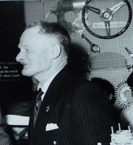 Vic Derrington at the 1961 Racing Car Show; note steering wheel at display
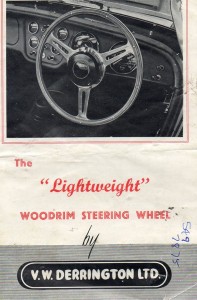 Front of a 1960 brochure
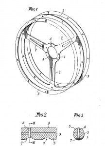 Original patent application of October 18, 1954
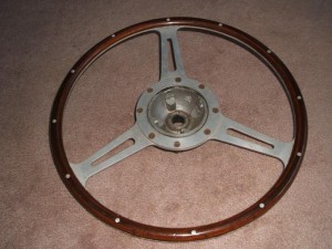
 Original Derrington 16” wheel with 8 screw mounting and 12 rivets.
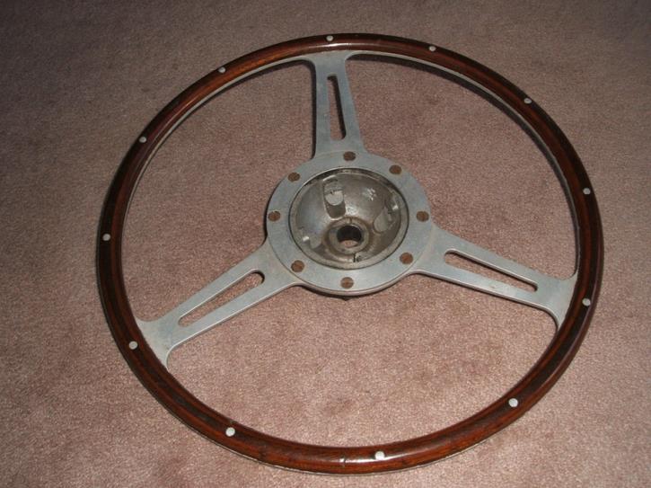
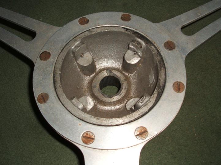
 Early Derrington wheel with 8 screw mounting.
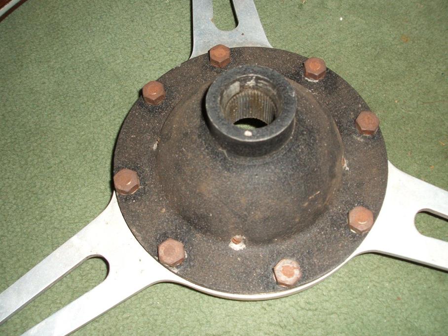
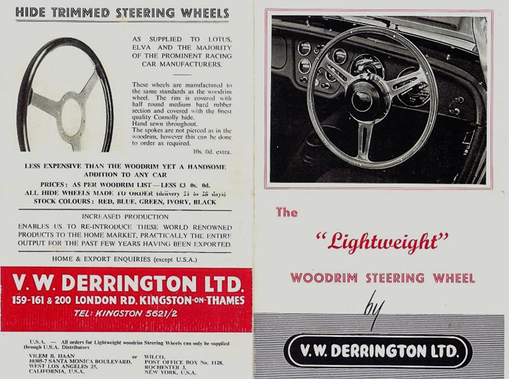
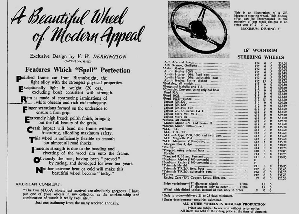

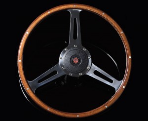 Modern Moto-Lita “Derrington wheel”
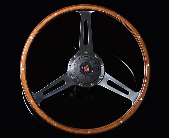
 Original AH 100 Le Mans “segmented” wheel with 9 screws and 24 rivets in “Derrington” style
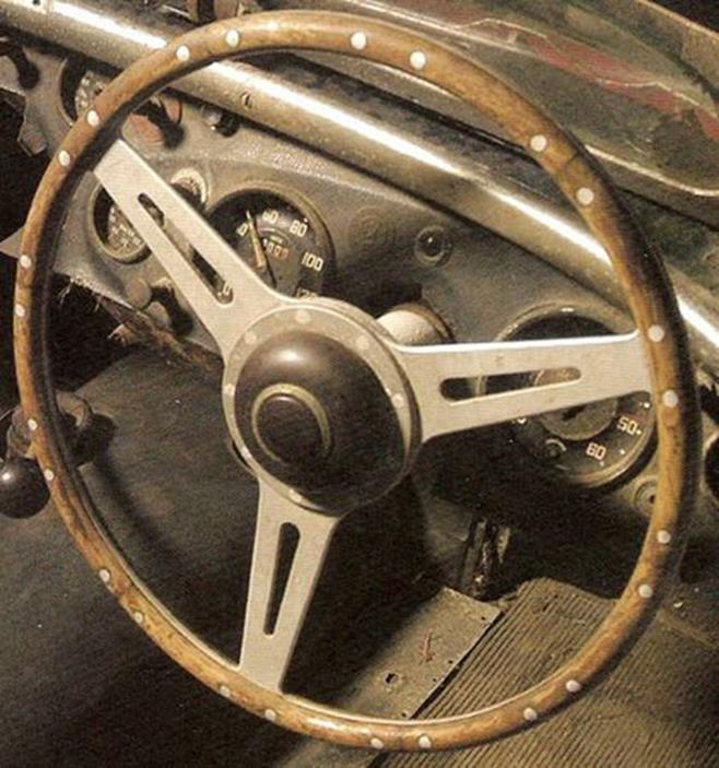
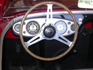 Strong resemblance, but not Derrington!
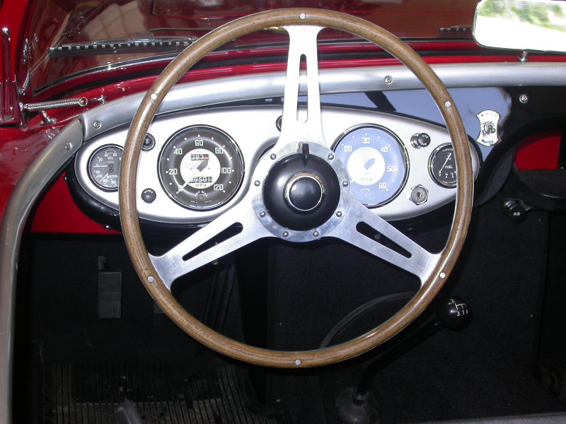
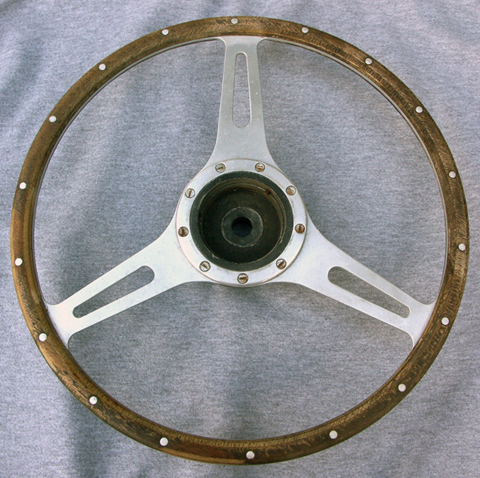
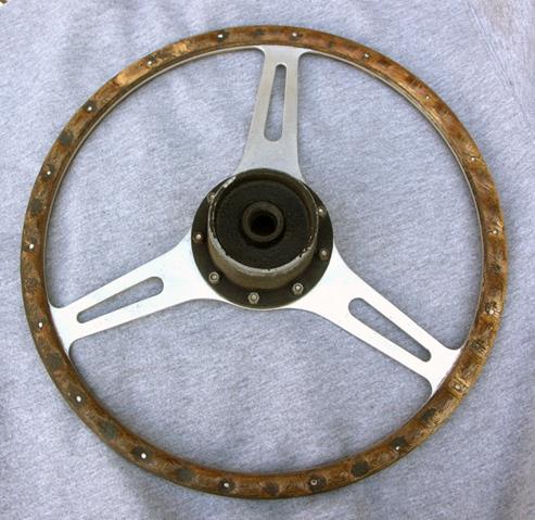
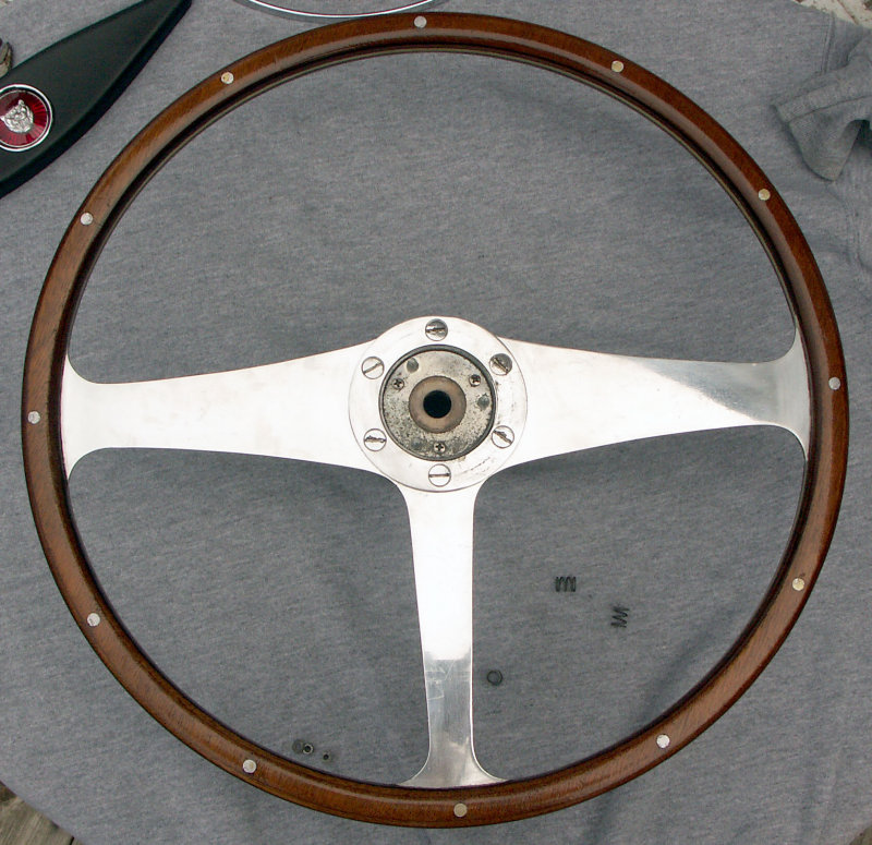

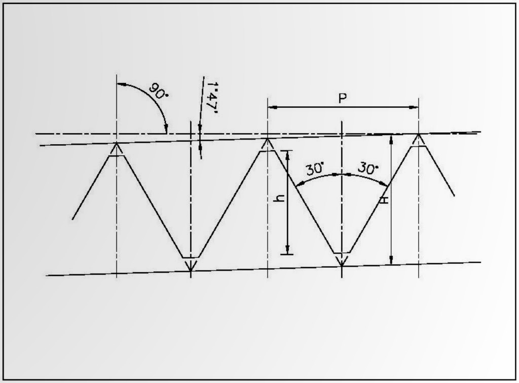
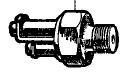
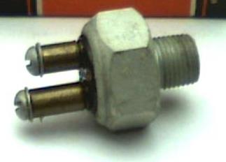
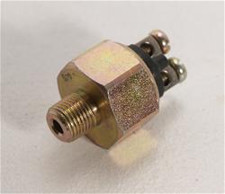
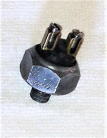
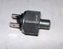
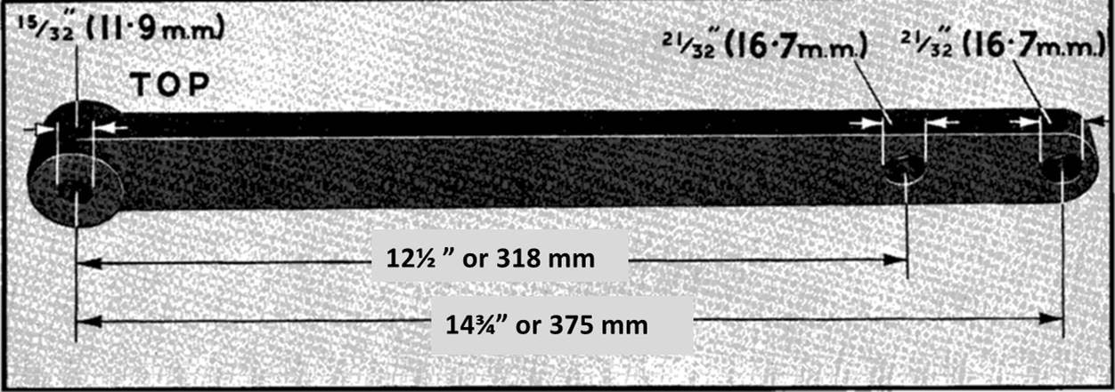
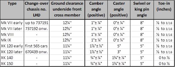
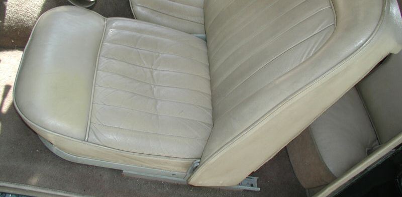
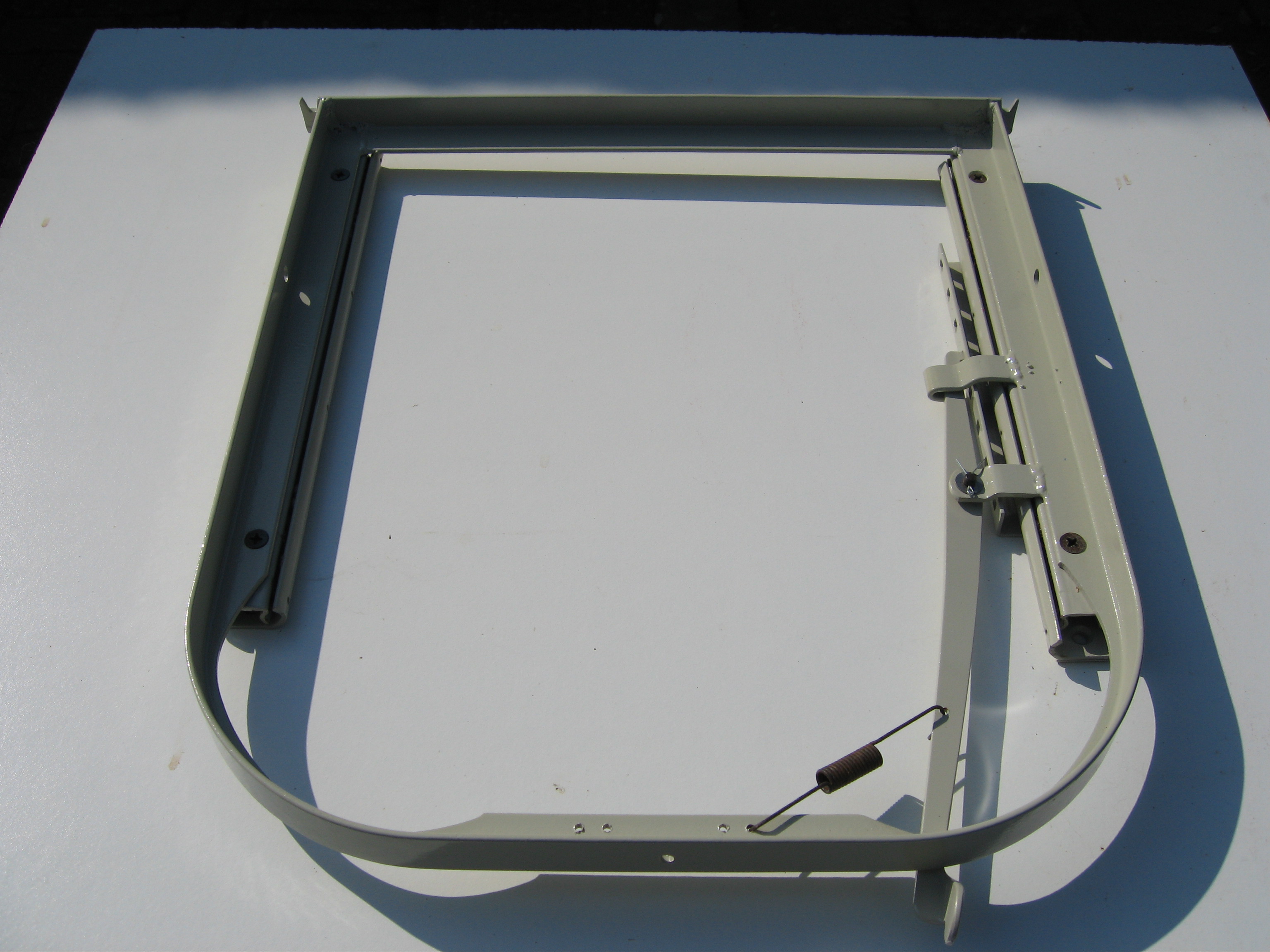
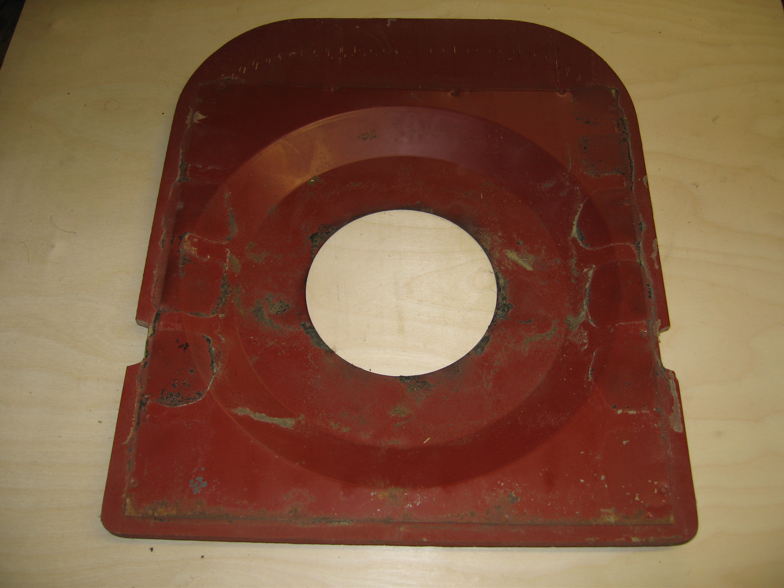
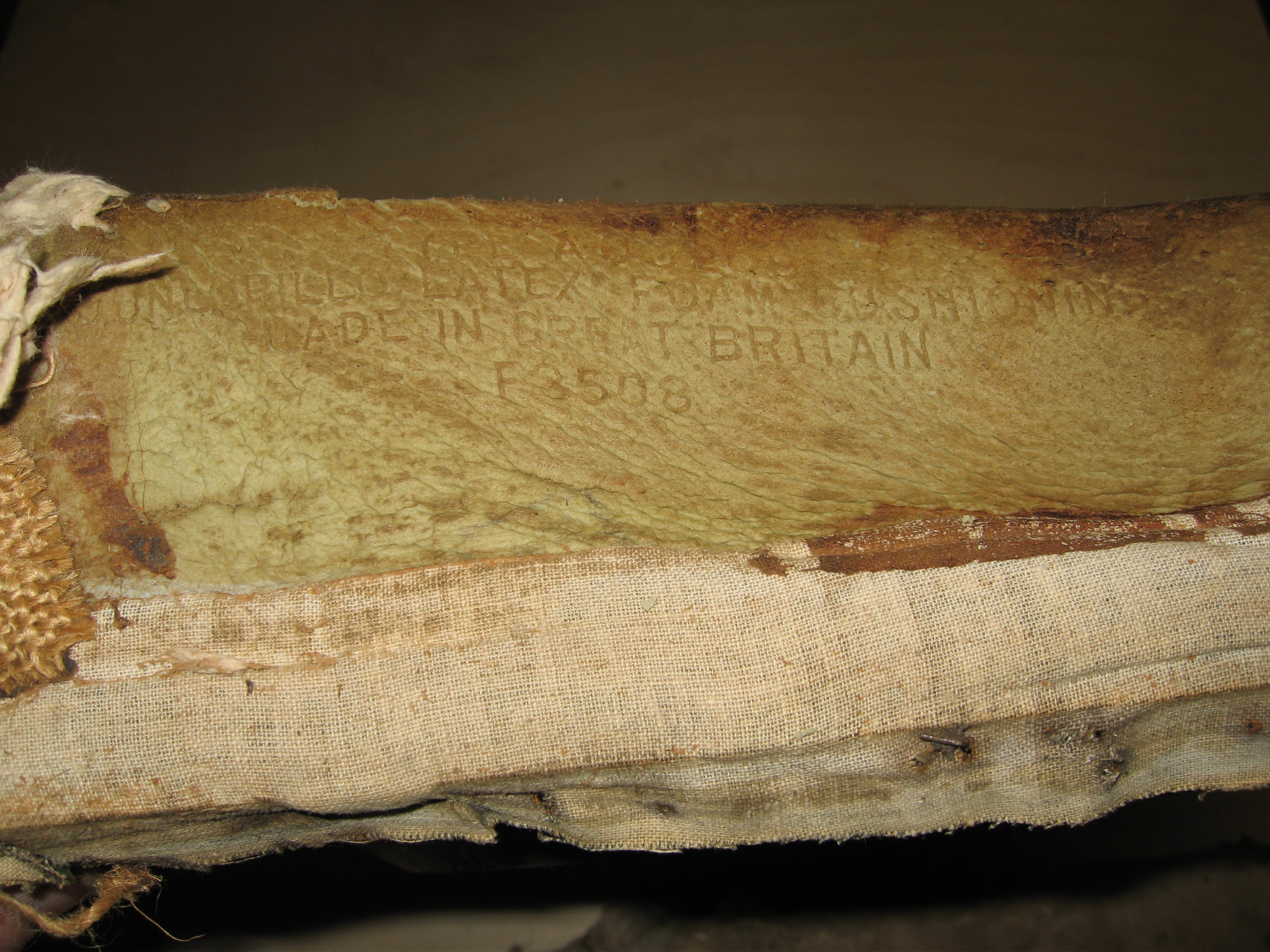
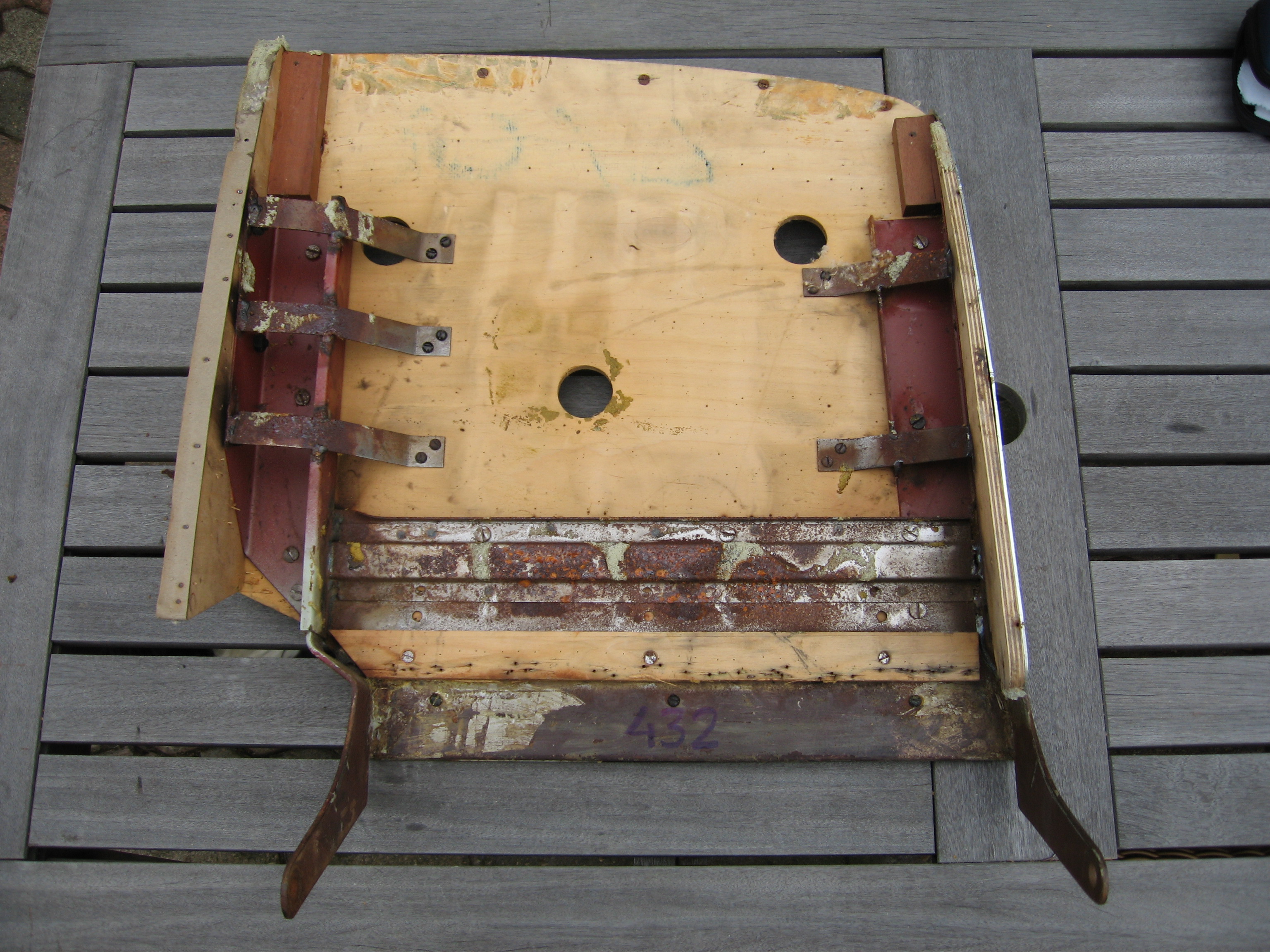

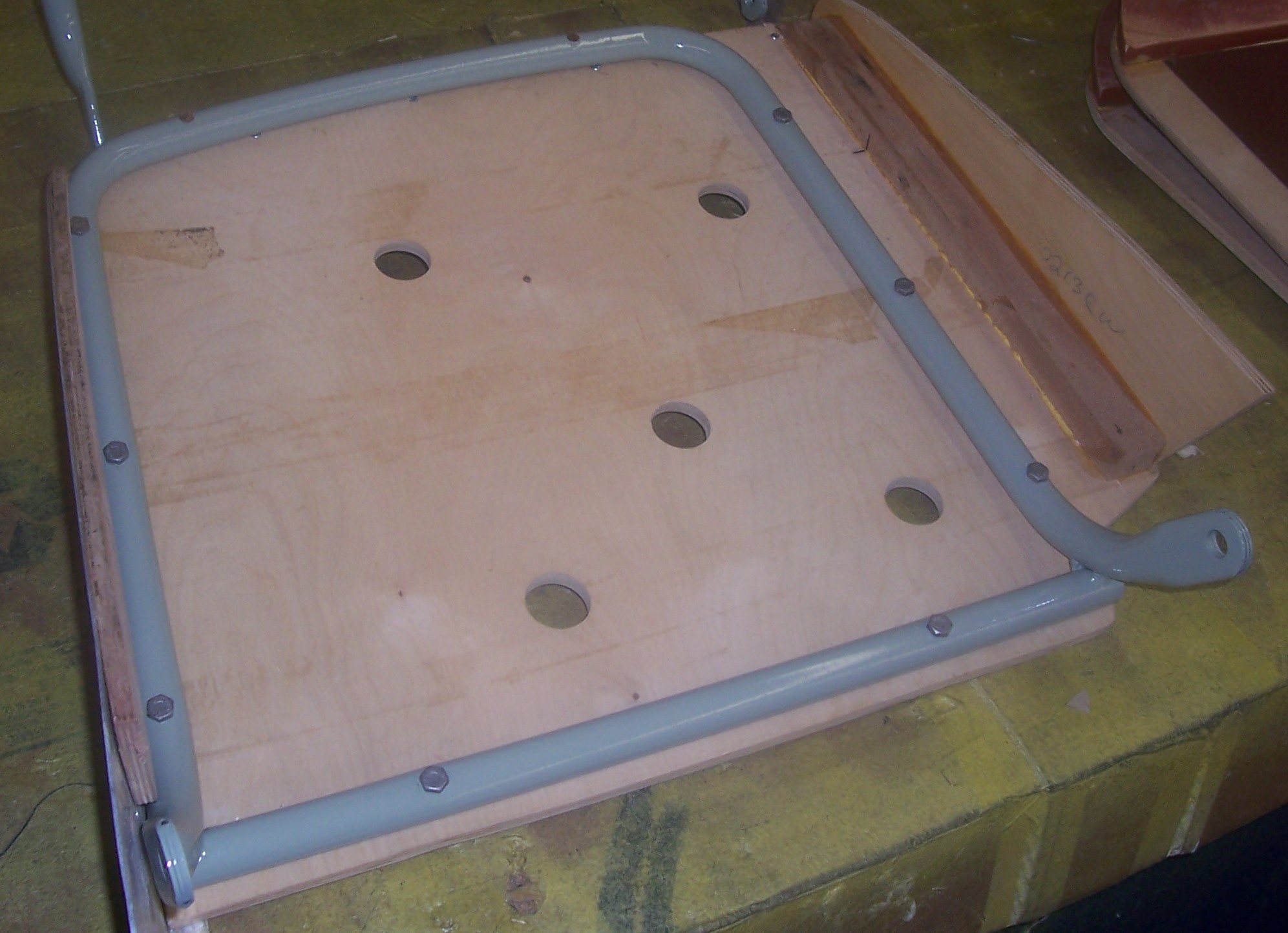
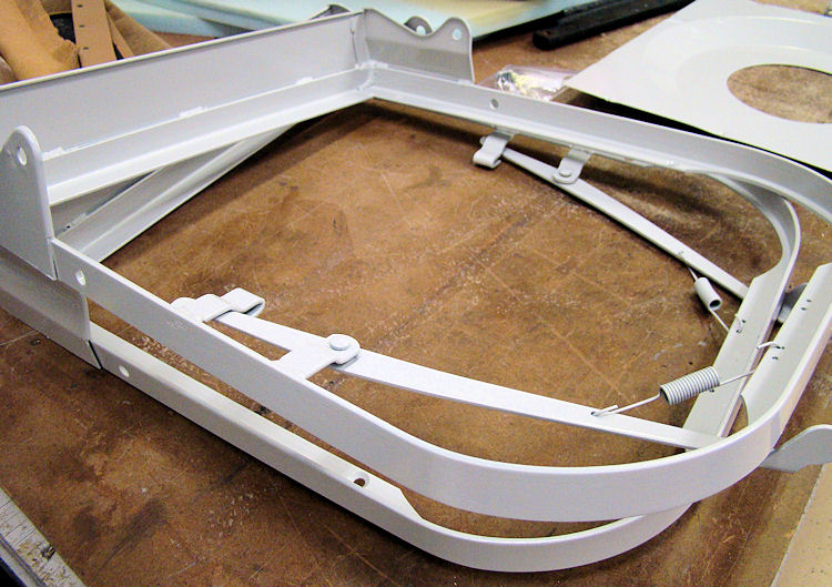
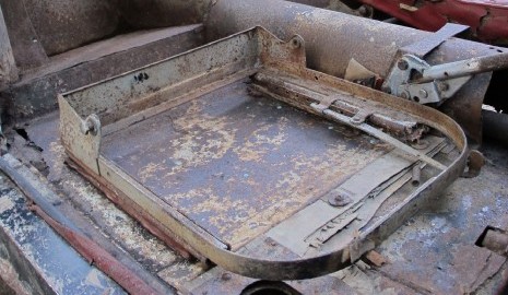
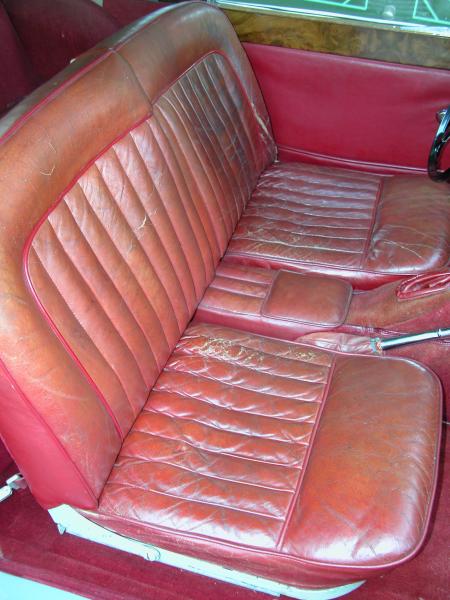
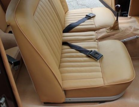
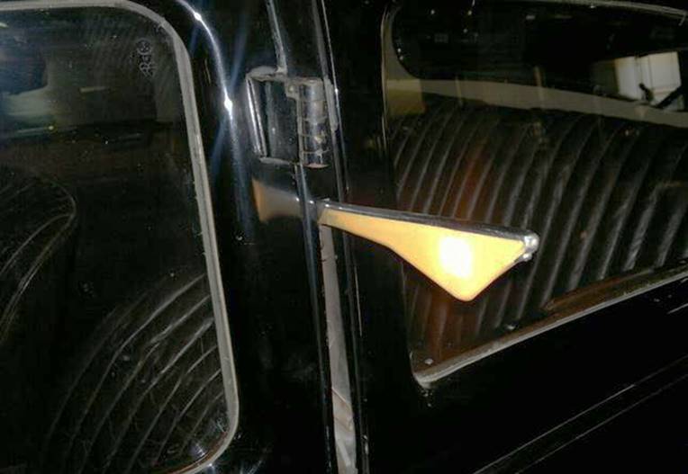
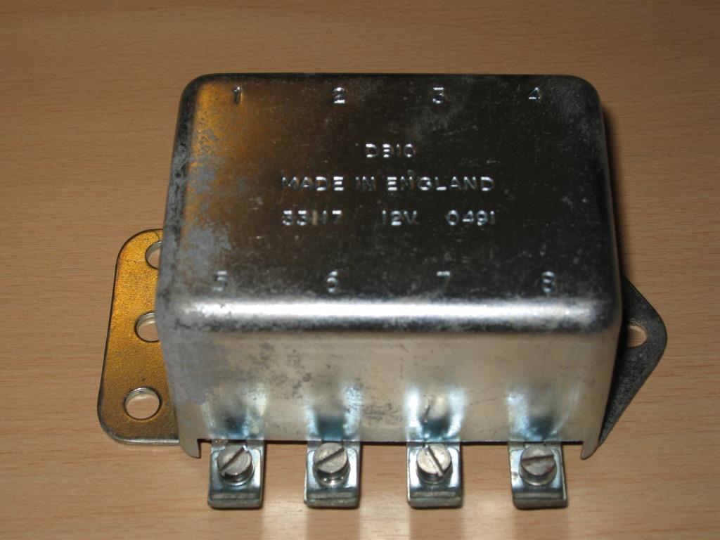
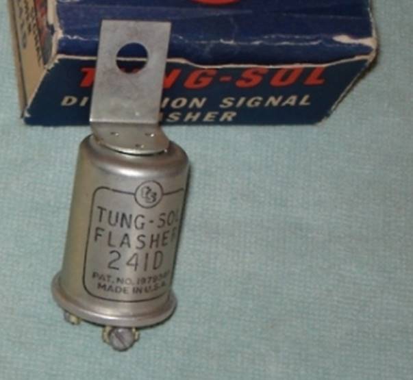
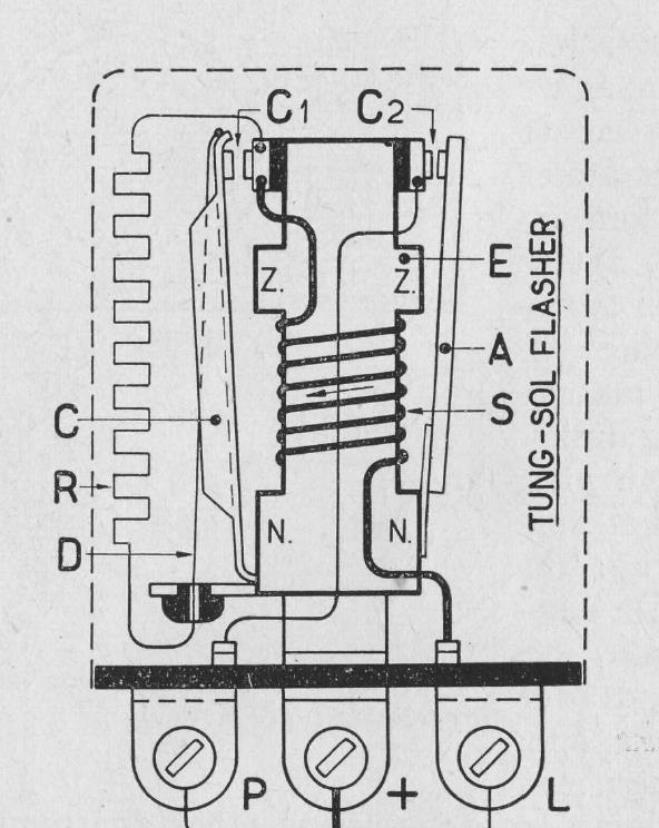
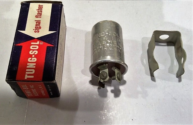
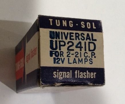
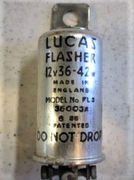
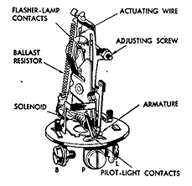
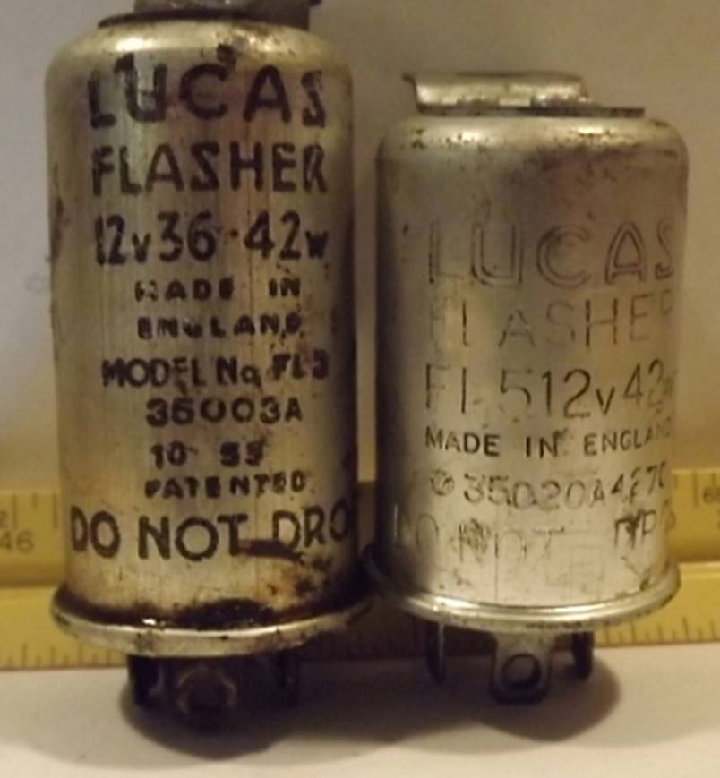
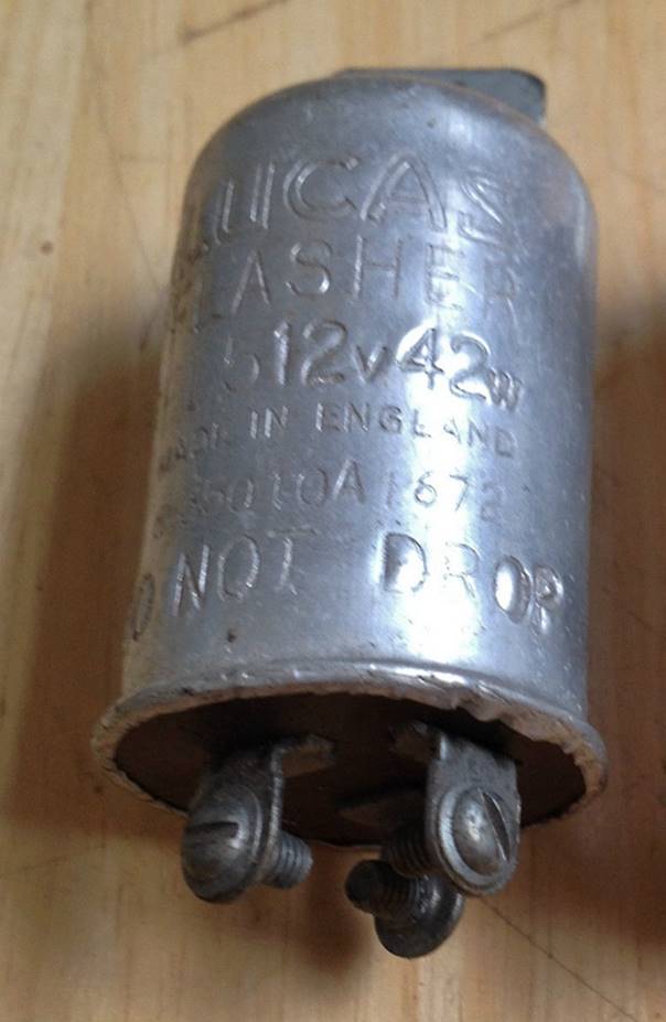
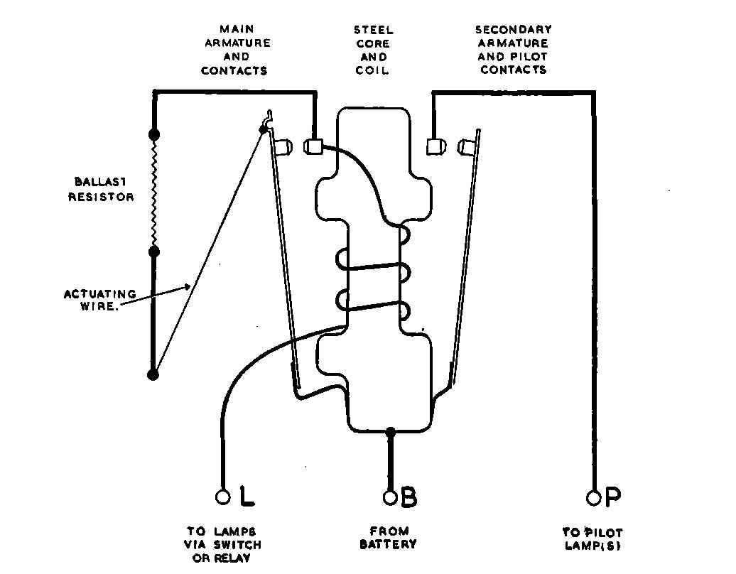
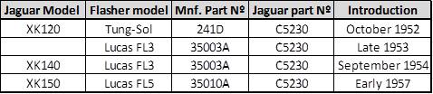
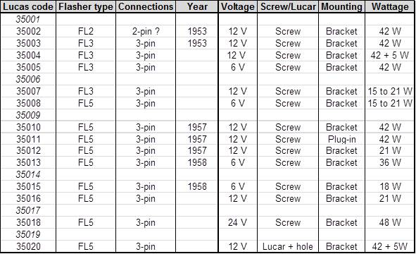
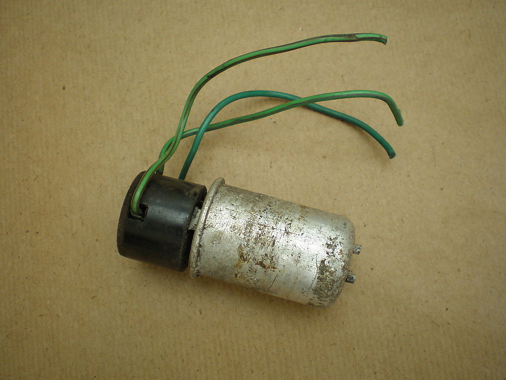
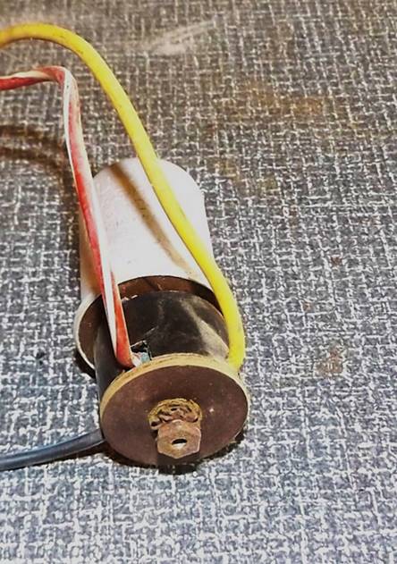

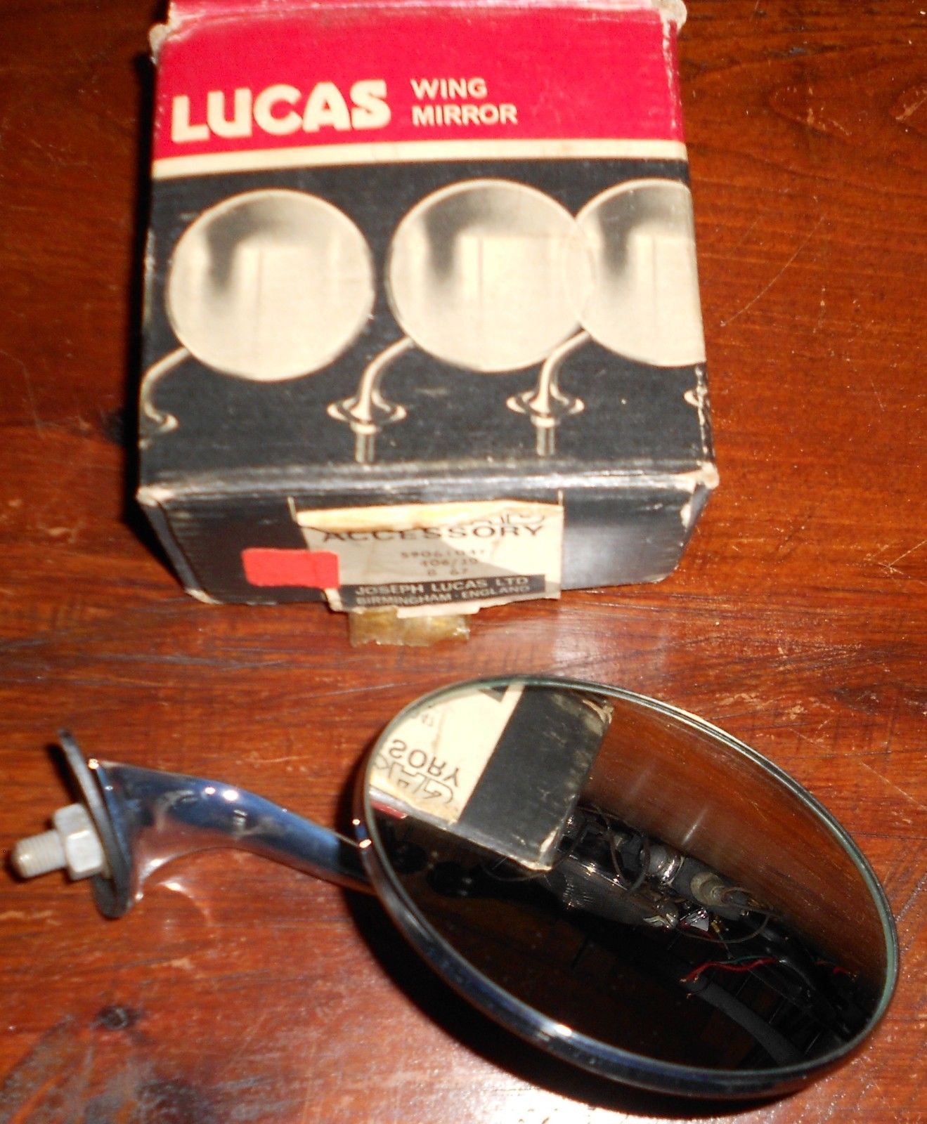
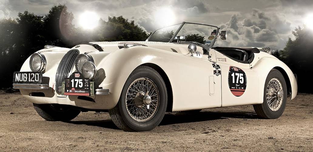
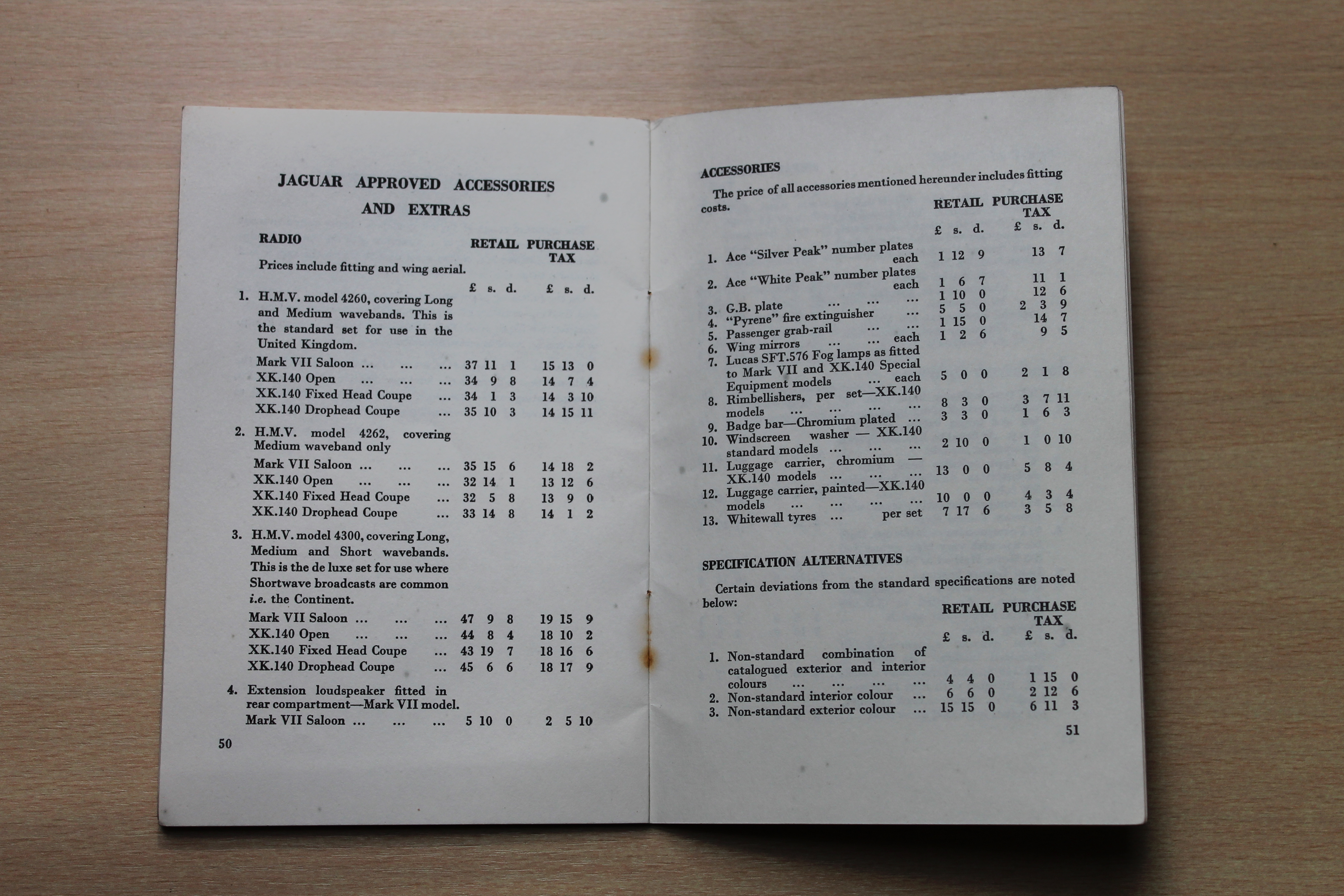
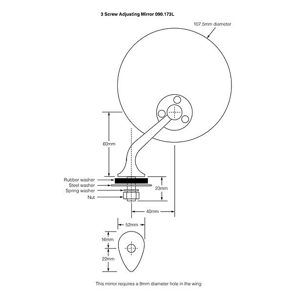
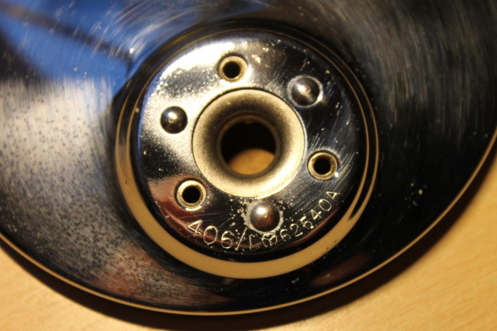

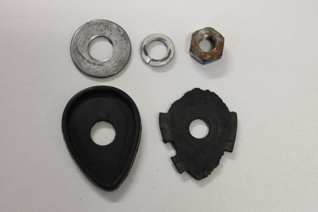
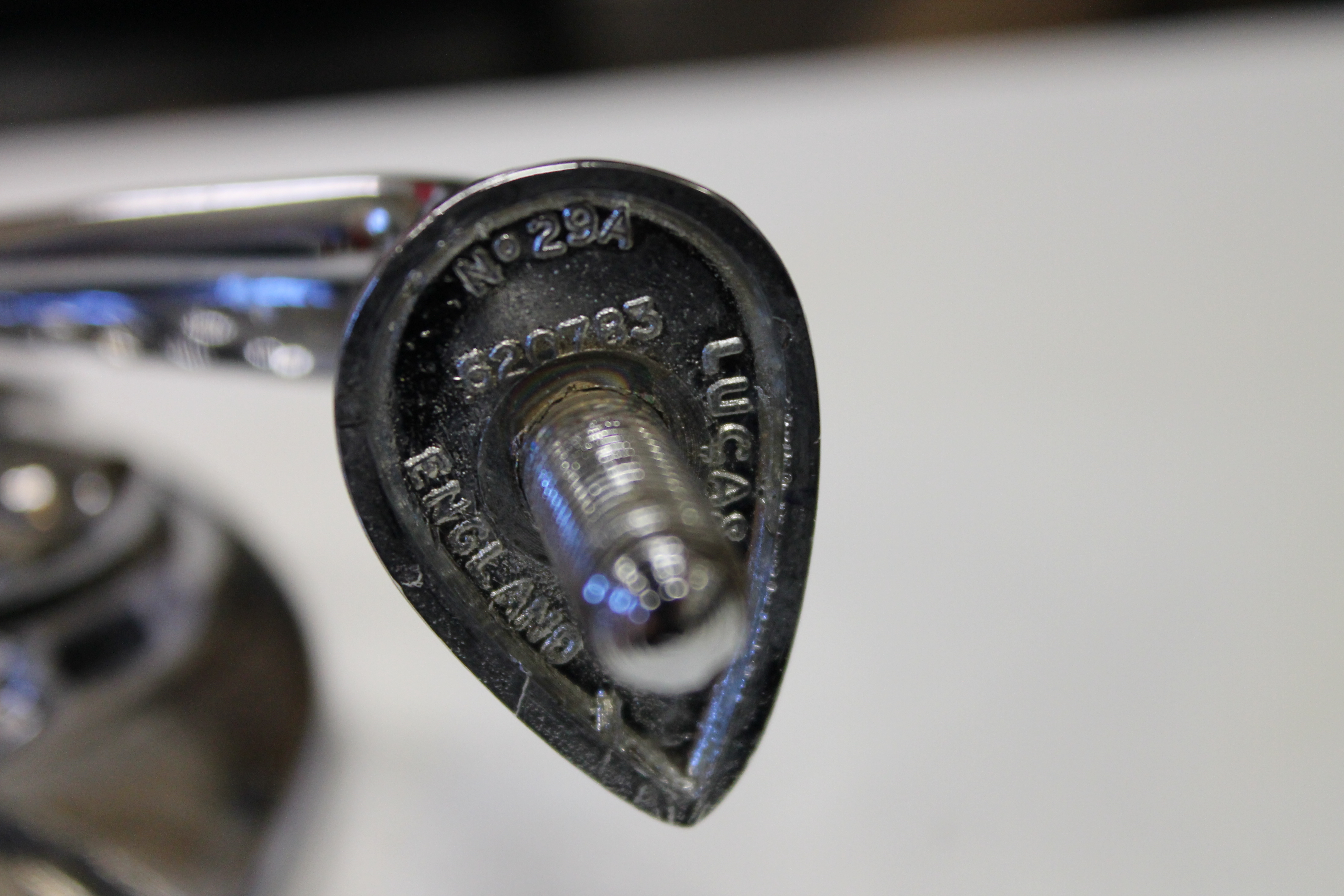
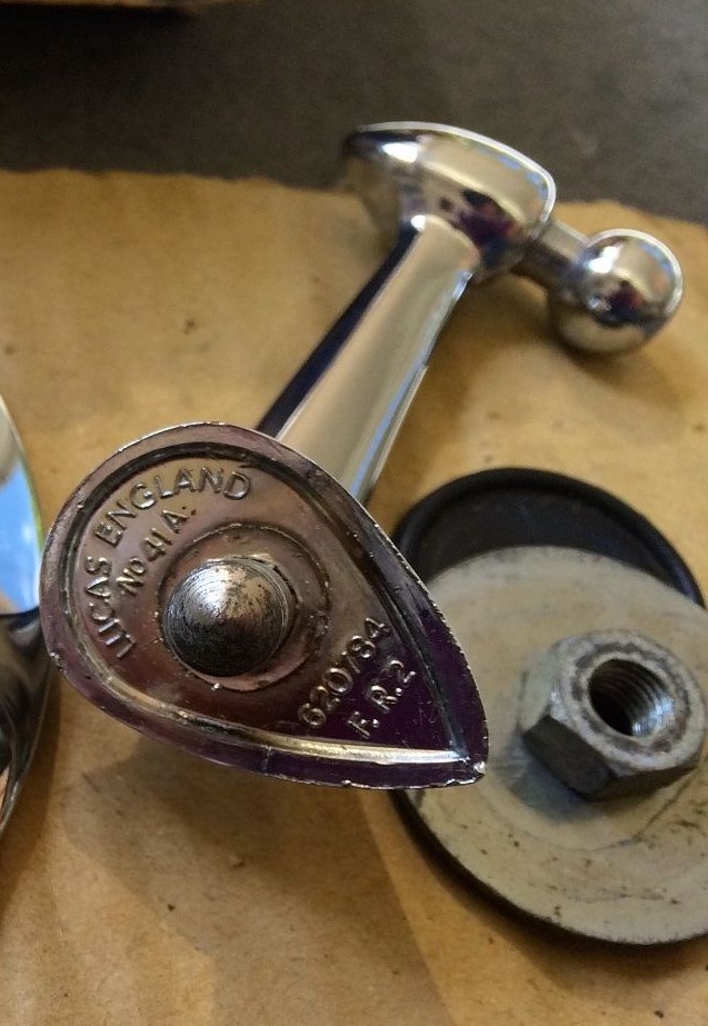
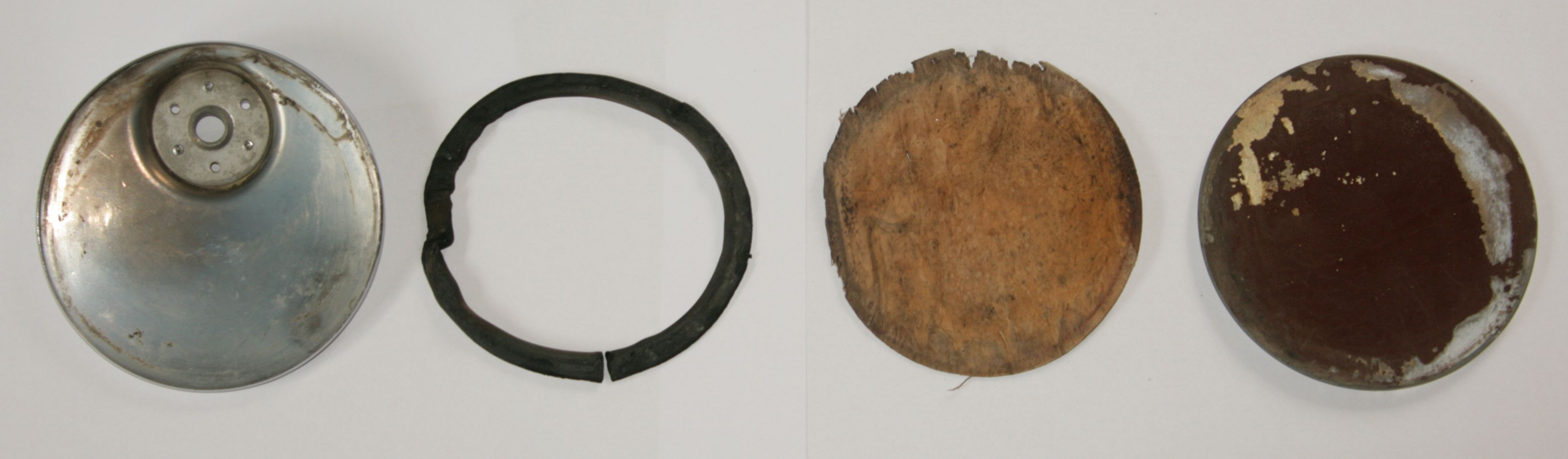
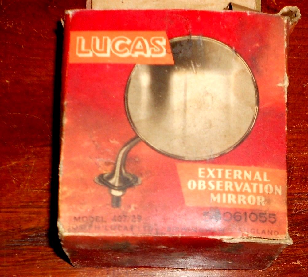
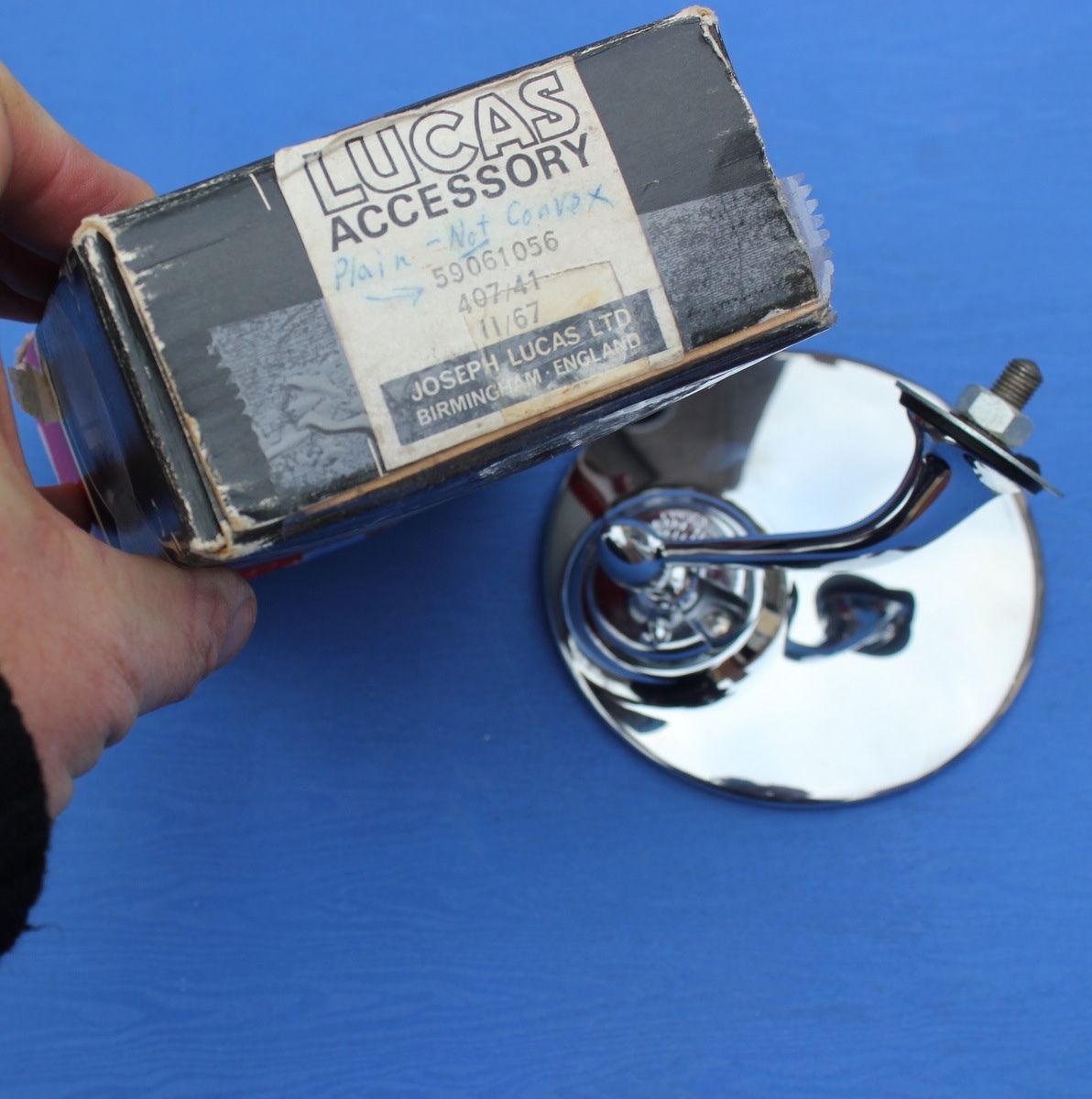

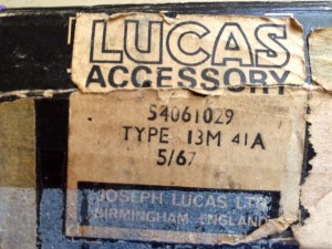 Lucas 59061047 LH Convex mirror Lucas 407/41A but other code 54061029