Category Archives: 06. Front Susp, Brake and Hubs
Wire wheels: worn hub and wheel splines
Leave a reply
Wire wheels on Turners
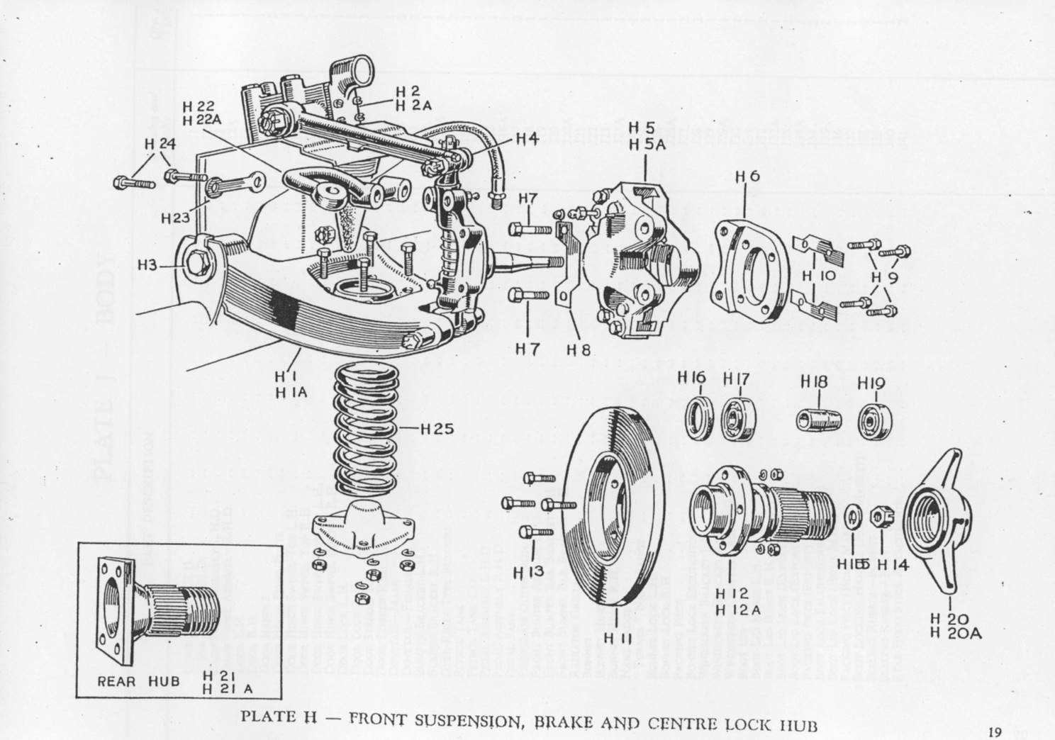
Many Turners received wire wheels either as a standard factory option or as a later “aftermarket” change. This was (always?) combined with a Girling Type 10 disc brake conversion at the front and required the use of special splined hubs on both axles. See page 19 of the Turner Parts Catalogue below. Turners used both 13 and 15” wire wheels.

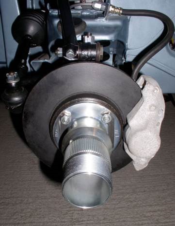 Special splined hubs for Girling Type 10
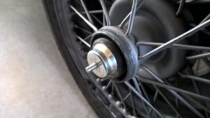
Wire wheel fixation
Detachable wire wheels have a different way of fixation compared to normal disc wheels, as they are mechanically “connected” to the axle hubs in two ways:
1. In a rotational direction by means of driving splines (serrations) on the (stub) axle hubs and driven splines on the inner wheel centre.
2. In an axial way by means of a (threaded) locking nut preventing the wheel to become disconnected from the threaded axle hub.
This article will not tackle the subject of which wire wheel types have been applied over the years; see the appropriate literature for that. We do want, however, to emphasise the potential danger of wire wheel fixation systems after many years of use (and abuse) to the point where they become even highly dangerous! In addition, some guidance is provided in checking whether a wire wheel can still be safely fixed to the car.
![clip_image002[4]](http://www.bobine.nl/turner/wp-content/uploads/2014/06/clip_image0024.gif "clip_image002[4]")
A – Locking thread on hub (left or right hand thread).
B – Driving splines on hub.
E – Driven splines of wheel centre.
Rudge-Whitworth fixation
The system of detachable and interchangeable wire wheels has been initially designed by John Pugh around 1910 but is better known under the (company) name of Rudge-Whitworth.
The resulting standardisation of detachable wire wheel fixations in Europe dates back to the 1920’s. The basis for this standard was the load to be carried per wheel and the required bearing diameter for that, resulting in a certain cross section for the hub. Note that the wheel type designation in the standard are basically structured around the (metrical!) dimensions of (then available) wheel bearings.
![clip_image002[6]](http://www.bobine.nl/turner/wp-content/uploads/2014/06/clip_image0026_thumb.gif "clip_image002[6]") Advertisement 1912
Advertisement 1912
![clip_image002[6]](http://www.bobine.nl/turner/wp-content/uploads/2014/06/clip_image0026.gif "clip_image002[6]")
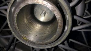
Wear on splines and thread
Over the years the thread of the locking nut and the hub itself may wear but (even more important) the splines on the hub and in the wire wheel centre may wear to the extent that the construction eventually becomes unsafe. Therefore it is wise to regularly check them and more in particular during any XK restoration as the condition and history of axle hubs and wheels are unknown.
Four dimensions are of importance here and have to be checked:
1. The maximum allowed inner diameter of the thread of the lock nut
2. The minimum allowed outer diameter of the thread on the wheel hub
3. The minimum allowed outer diameter of the splined hub
4. The maximum allowed inner diameter of the inner wheel centre splines
Please note that wear of splines and thread is accelerated if the wheel is not fitted tightly!
Cross-section of Rudge-Whitworth hubs
The principle wheel type designation according the Rudge-Whitworth standard refers to the maximum size of an outer wheel bearing (in millimetre) which can be used with that hub. The actual hub diameter is measured across the outside of the splines on the axle hubs (not the wheel splines).
|
Wheel Type |
Actual hub diameter |
Number of splines |
Spline length Long Hub |
|
35 |
52 |
62 |
56 |
|
42 |
62.5 |
75 |
62 |
|
52 |
73 |
88 |
62 |
|
62 |
82.5 |
100 |
78 |
|
72 |
92 |
112 |
84 |
|
80 |
102 |
124 |
87 |
|
90 |
111.5 |
136 |
94 |
|
100 |
123 |
150 |
97 |
|
120 |
137 |
168 |
101 |
Two wire wheel types are normally used on British sports cars: type 42 and 52. Turner opted for the smaller Type 42 wire wheels also due to the rather limited weight of their sports cars. The (course) thread of wire wheels has a top angle of 60° and a pitch of 8 TPI (or 3.2 mm) although some earlier versions may have used 12 TPI (or 2.1 mm).
 Alexander-Turner with 15″ wire wheels

Dimensional requirements for Type 42 wire wheels: worn or still OK?
Further to the aforementioned important testing criteria, the survey below gives specific information regarding when a splined hub, wire wheel or locking nut should be replaced.
- The locking nut should be checked for wear on the (internal) thread. If a cylinder with an outside diameter of 2.211” or 56.2 mm should fit in the locking nut, wear has progressed to the extent that the locking nut has to be replaced.
- If a tube with an internal diameter of 2.291” or 58.2 mm fits over the thread of the axle hub, wear has progressed to the extent the complete hub has to be replaced.
- If a tube with an internal diameter of 2.424” or 61.6 mm fits over the splines of the axle hub, the complete hub has to be replaced.
- If a cylinder with an outer diameter of 2.374” or 60.3 mm fits in the internally splined wheel centre, the complete wire wheel has to be replaced.
Note that the above dimensional requirements are no more than minimum requirements! As an example: wire wheel constructions fulfilling the above requirements have a remaining overlapping contact height of the splines of no more than (61.6 – 60.3 =) 1.3 mm. Although the contact surface is of course larger due to the 60° V angle of the spline and the length of the spline (here 37 mm), in comparison a new type 42 spline has a contact height of 62.3 – 59.6 = 2.7 mm, meaning that the (safety?) margin has been more than halved.
So don’t use any hubs or wheels with spline dimensions below the above given minimum requirements!
Stub axle repair Turner 950
After more than 60 years of (intensive) use the stub axles of Turner 950’s may have suffered to the extend that e.g. bearings have too much play on the axle and replacement is required. Especially those having the special Girling Type 10 disc brakes mounted, may be a candidate for stub axle replacement.

New complete stub axle/kingpin forgings (BMC part number BTA 744 and 745) are difficult (impossible) to find and used replacements may have suffered even more than the old ones you are about to replace.
Installing a new stub axle may be the solution but requires certain skills and equipment but can be done. The attached drawing could offer some guidance for this replacement: any well equipped shop could make this axle. The old axle has to be machined from the upright and the diameter and length of the machined hole and new stub axle should be matched to secure a good press-fit.
New bearings SKF 7205 (Ø 25,0 x 52,0 x 15 mm) and SKF 7303 (Ø 17,0 x 47,0 x 14 mm) should be installed and the bearing spacer (88G321) between the 2 bearings checked for correct dimensions as the correct bearing play is determined by the length of this part in combination with the castle nut adjustment. Use new washers (2A 4003) and castle nuts (51K 328).

Alexander-Turner Brake Servo
Alexander-Turner Brake Servo
The Turner-Alexander had a number of optional extras in 1959 and 1960, like Girling front disc brakes and a Lockheed brake vacuum servo: indeed an intriguing combination! Girling front disc brakes were £25 whereas for the Lockheed brake vacuum servo another £20 had to be paid.
The Girling Type 10 disc brakes are described under the Category “Brakes” and “Tuning” on this website. This document describes the Lockheed brake servo.
Lockheed 5½” Brake Servo
At the end of the 50’s Lockheed had already a number of brake servo system in their programme, but most of them based on a vacuum piston moving in a cylinder with leather or rubber piston rings. A new generation using a rubber diaphragm was introduced allowing for a more compact design, making the vacuum servo piston no longer required.
Thus the new 5½” Brake Servo version was chosen by Alexander to assist the new Girling Type 10 disc brakes that required a (much) higher pedal pressure.

There were various versions with different slave cylinder sizes: 5/8”, 11/16”and 7/8” diameter all sharing the same vacuum housing. Most probably Alexander had chosen for Lockheed servo type number 112753 with a 7/8” slave cylinder, which was an “Installation Kit” without specific applications mentioned. There was an alternative “Installation Kit” which had a later Lockheed type number 4257-064, having the same slave cylinder dimensions but a different Air Control Valve housing.

A similar Lockheed servo was later introduced on the Mk1 Cooper S models (1963 onwards). All Mini Cooper S Mk 1 models came with this Lockheed type 5½” vacuum-operated brake servo unit as standard, fitted to the RH wing valence of the engine compartment. Both end covers (dishes) and the collar of the brake servo were cadmium plated, giving an unpolished bluish-white finish. The brake servo slave cylinder should be finished in matt black.
The Cooper S brake servo looks similar to the original Alexander-Turner versions and could be used.
Spare Parts
The servo Lockheed Nº 112753 required a Major Repair Kit Nº SSB.1003 and an Air Control Kit Nº SSB.1004.
The servo Lockheed Nº 4257-064 required also Major Repair Kit Nº SSB.1003 but a different Air Control Kit Nº SSB.1002.
The Cooper S servo required a Major Repair Kit Nº SSB.1036 and an Air Control Kit Nº SSB.1002.

Lockheed Air Control Kit Nº SSB.1004

Lockheed SSB.1002 Air Control Valve kit

Lockheed SSB.1036 Repair kit. The repair kit SSB.1003 will look similar.
Girling Front Disc Brakes on Turners.
 Period Girling advertisement mentioning Turner next to all the “big guys”

In 1959 the Turner 950 BMC-A and Coventry Climax got disc brakes as a factory option. This was the recently introduced (second generation) Girling Type 10 disc brake system. Girling (part of the Lucas group) began experimenting with disc brakes on race cars in 1952. An early generation Girling Type A solid caliper 11″ disc brakes had been used on the Triumph TR3 from 1956. Turner (as a small company) was one of the earlier adopters (1959) installing disc brakes on their sports cars. It required the use of special mounting brackets to mount the callipers to otherwise standard front hubs.


Girling Type 10 Callipers (Turner H5 and H5A) and Mounting Brackets (Turner H6) on my Alexander-Turner 950
 Complete Girling front brake system on Turner 950
Girling Type 10 Disc Brakes
Applications:
- Austin Healey Sprite Factory Conversions (Sebring Sprite) from 1959 onwards
- Berkeley Bandit from 1960 onwards
- Turner 950 BMC-A (optional) and Coventry Climax from 1959 onwards
Girling part no Description (and Turner reference number)
- 64032502 Calliper assembly LH (Turner H5)
- 64032503 Calliper assembly RH (Turner H5A)
- 64325873 Piston
- 64325183 Calliper mounting bracket (Turner H6 2x)
- 64325186 Disc (Turner H11)
- 64325027 (GDB 509 – DS 5S) Pad
- 64325418 (GDB524) Pad (alternative)
- 64325022 Pad Retaining Pin
- 64325009 Retaining Pin Clip
- SP2507 Service kit callipers
 Exploded view of Type 12 calliper; Type 10 is similar


Pistons 64325873 tend to corrode after many years of use (moist in brake fluid!) and are hard to find. I had new ones made in Cr Ni steel according above left drawing. Also the pins 64325022 have a hard life and making new ones is not so difficult (see 2nd drawing). These items are both used in Type 10 and Type 12 systems.
Girling Type 12 Disc Brakes
Applications:
- Triumph Herald Oct 1961 onwards
- Triumph Vitesse “6” 1962 onwards
- Turner GT and Coventry Climax 1220 from 1962 onwards
Girling part no Description
- 64032604 Calliper assembly LH
- 64032605 Calliper assembly RH
- Non-Girling part Disc
- 64325708 Pad
- SP2529 Service kit callipers
Discs dimensions for Turner Sports 950 BMC-A and Coventry Climax from 1960 onwards
Original Girling code was 64325186 (for Turner H11)
| Dimensions |
Metric |
Inch |
| Outer diameter |
Ø 217 |
8 9/16” |
| Overall width |
23.5 |
15/16“ |
| Disc thickness |
9.6 |
3/8” |
| Minimum allowed thickness |
8.6 |
|
| Centre hole diameter |
Ø 63.5 |
2½ |
| Bolt pitch circle |
Ø 87.3 |
3 7/16 |
| Bolt hole (4x) |
Ø 9.6 |
3/8” |
These Girling discs are no longer available. Whether Girling also provided the hubs is still point of investigation. The origin (and supplier) of the Turner hub is unclear.
Other potential Turner suppliers had different dimensions: Austin-Healey Sprite has a bolt pitch circle of Ø 81.0. Triumph (Herald, Spitfire) had indeed a value of Ø 86.6 mm, but the disc is otherwise different (overall width and diameter) and cannot be used.
The Ford Escort Mk1 1300 GT disc comes very close with a bolt pitch circle of Ø 86.4 although this is a non-Girling system.
Front Brake Pads for Turner 950 BMC-A and Coventry Climax from 1960 onwards
Original Girling part number 64325418 or GDB524(no longer available). Dimensions: 62 x 43 x 15 mm. Same part number is also used as rear brake pads on Lotus cars:
- Elan 1.5 (1962-1965)
- Elan 1.6 (1966–1974)
- Elan 2+2 1.6 (1967-1971)
- Elan 130/4 (1971-1974)
- Elan 130/6 (1972-1975)
- Elite 1.5 (1958-1964)
- Elite Mk II (1961 on)
Corresponding Lotus part numbers:
- 036J6066 (non-servo version)
- 036J6064 (servo version)
Other brands that supply this product:
- NU-TEXA DP46
- EBC DP145 complete axle set
- Bendix B300119
- Ferodo FER DA3 FF 517

 Bendix B300119

 Ferodo DA3 FF 517
Modification of Ford Escort Mk1 1300 GT Front Brake Discs
Ford Escort Mk1 GT discs can be made to fit with slight machining. Original Ford part number: (Ford GB) 3026E1123C/68AB1125AA; (Ford D) 1450669. This disc is used on Ford Escort Mk1 1300 GT (from 8/1969 till 11/1974). For dimensions and tolerances see Brembo drawing (below).
Other manufacturers that supply this disc type:
- Brembo 08164310
- Ferodo DDF 009
- EBC D080
- SAP motor parts BDC 1018
- Autonational BDC 0079
![]() Comparison of dimensions Turner versus Ford disc:
Comparison of dimensions Turner versus Ford disc:
| Dimensions |
Turner |
Ford |
| Outer diameter |
Ø 217 |
Ø 218.6 |
| Overall width |
23.5 |
23.3 |
| Disc thickness |
9.6 |
9.65 |
| Minimum allowed thickness |
8.6 |
8.6 |
| Centre hole diameter |
Ø 63.5 |
Ø 63.1 |
| Bolt pitch circle |
Ø 87.3 |
Ø 86.4 |
| Bolt hole (4x) |
Ø 9.6 |
Ø 9.9 |
The Ford Escort Mk1 GT disc has a different pitch circle (about 1 mm smaller) which does not allow a direct exchange. Three possible solutions:
- New holes have to be drilled at the correct pitch circle Ø 87.3 mm.
- The holes in the Ford disc have to be enlarged from Ø 9.9 to Ø 10.5 mm.
- The holes in both hub and disc to be enlarged to Ø 10.0 +0.05 mm.

Girling Type 10 on Sprite Factory Conversions (Sebring Sprite)
The Donald Healey Motor Company supplied conversion parts (as per Sebring Sprite) including wire wheels and disc brakes with special Ø 8½” (216 mm) front discs and Girling callipers (1958-1961).

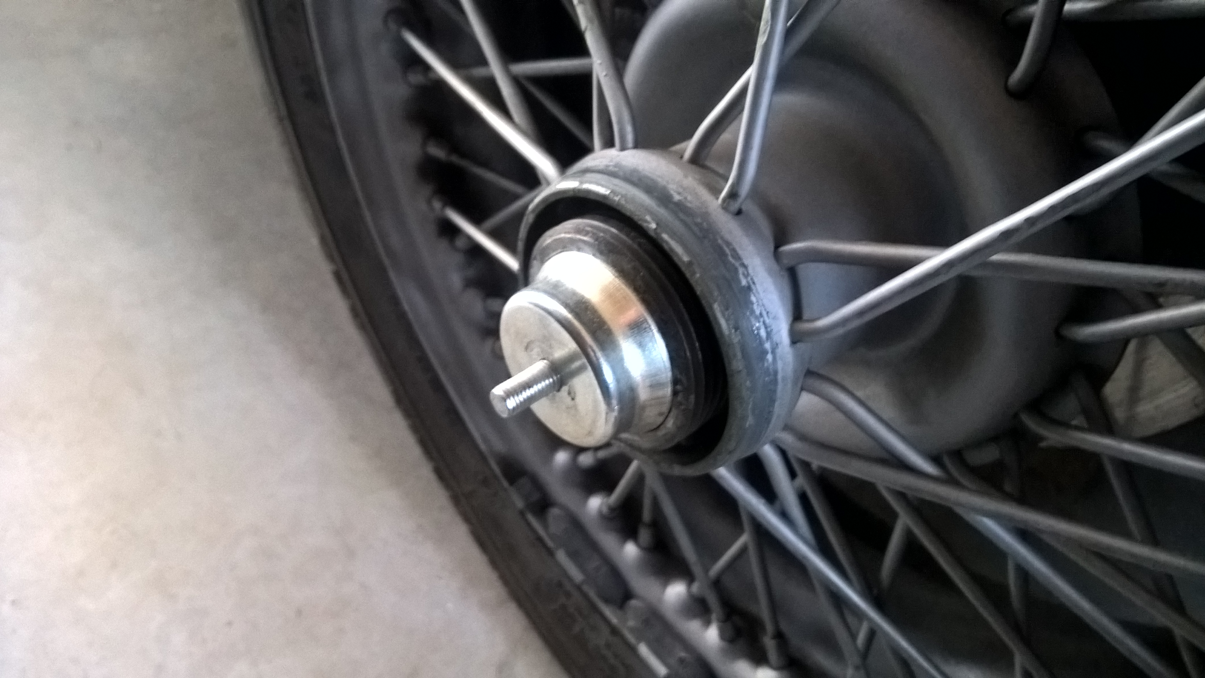
 Original front splined hubs and a pair of new replacements (as reference for Turner H12 and H12A).
 Dust caps (foreground) are larger than standard B.M.C. items. Caps are tapped home inside hub.


 Original Girling ‘Type 10’ brake callipers, including pads and stub axle mounting brackets.

 Stub axle mounting brackets for the Girling Type 10 set-up.
 Original Girling ‘Type 10’ calliper
Alexander Front Anti-roll bar
Description of the ALEXANDER Front Anti-roll torsion bar for Turner
The Alexander Anti-roll bar system consists of a standard 11/16“ (17.5 mm) torsion bar and an additional ¾” (19.0 mm) rod for increased stiffness.
![clip_image002[4]](http://www.bobine.nl/turner/wp-content/uploads/2013/05/clip_image0024.jpg "clip_image002[4]") Original Alexander folder
Original Alexander folder
The standard bar connects LH + RH lower wishbone (via rubber mountings) with the front end of the chassis (rubber mounted distance brackets). The ALEXANDER Anti-roll bar was available as an option for cars like the A35, A40, Sprite/Midget and some larger BMC-B engined cars from the early 60’s. Also Turner offered an Anti-roll bar as an option.
The additional stiffening bar is connected via four brackets, securing the ¾” bar to the 11/16” bar and is probably a later addition. The four brackets are branded: DEE JAY RACING.
Parts list:
- Torsion bar Ø 11/16” 1 pc
- Suspension bracket (bar to chassis) 2 pcs
- Rubber bush for 2. Ø 5/8” inner x Ø 1 1/8”outer x ¾” 4 pcs
- Pressure plates for 3. 4 pcs
- Bolt for 4. 3/16” BSF x 2” 4 pcs
- Self-locking nut for 5. 3/16” BSF 4 pcs
- Bolt (susp. bracket to chassis) 3/8” UNF (5/8”) x 4” 2 pcs
- Self-locking nut 3/8” UNF 2 pcs
- Washer 5/8” large (3D) 2 pcs
- Bolt (bar to lower wishbone) 5/16” UNF (3/8”) x 3” 2 pcs
- Self-locking nut 5/16” UNF 2 pcs
- Rubber bush for 10. Ø 3/8” inner x Ø 1 1/8”outer x ¾” 4 pcs
- Dish for 12. 4 pcs
- Washer (wishbone side) 5/16” large 2 pcs

Additional Stiffening Bar:
15. Torsion bar Ø ¾” 1 pc
16. Connecting bracket (short, centre) 2 sets
17. Connecting bracket (long, side) 2 sets
18. Bolt (for 16 + 17) ¼” UNF x 13/4” 8 pcs
19. Self-locking Nut ¼” UNF 8 pcs