First season Ken MacKenzies Alexander-Turner
The typical atmosphere of club racing in the 50’s and 60’s is regarded as pure nostalgia by many of us nowadays. The following article describes the scene, following Wing Commander Ken Mackenzie through the 1960 season, participating with an Alexander-Turner 950 in the Autosport Series Production Sports Car Championship Class A.
It was the very early morning of Easter Monday 18 April 1960 when the transporter, so kindly provided by Alexander Engineering of Haddenham, left Northwood on its way for the 100 mile journey to Mallory Park. Quite an improvement over the “hotted-up“ Volkswagen Beetle, the driver’s daily transportation, that until then had to do the job. This was the day: the beginning of another season in the Autosport Series Production Sports Car Championship for Ken Mackenzie.
Wing Commander K.W. Mackenzie had quite a background in racing by now. Whilst in the RAF Reserve in 1939 he started building, modifying and rallying various cars. After the war he started racing in 1956 with various cars, including RWG and an Elva Climax. In 1958 he was fairly successful in a (works supported) MGA gaining first place in the 1600 cc Class in the Autosport Championship and doing even better with the (Alexander suported) Austin Healey Sprite (Registration Number 6 TMT) during the 1959 season (gaining 20 places during the season), teaming up with (Squadron Leader) Paddy Gaston and Chris Tooley and winning the Championship.
It was only a few weeks before that Mackenzie had taken delivery of the brand-new Turner 950 Sports, built and assembled by Turner of Wolverhampton on their premises at Pendeford Airport. Confronted with the convincing results of Turners in the 1959 season (Bob Gerard becoming overall winner, Austin Nurse and B. Gilbert gaining several successes) Ken Mackenzie decided to change over in 1960 to the successful creation from Turner Sports Cars. But Ken Mackenzie wanted more – he wanted a winner.
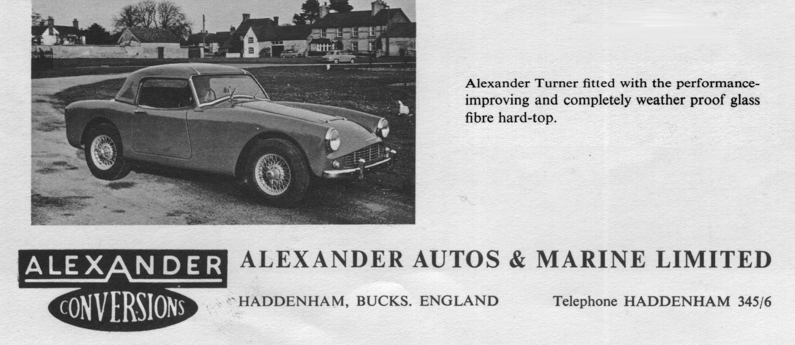
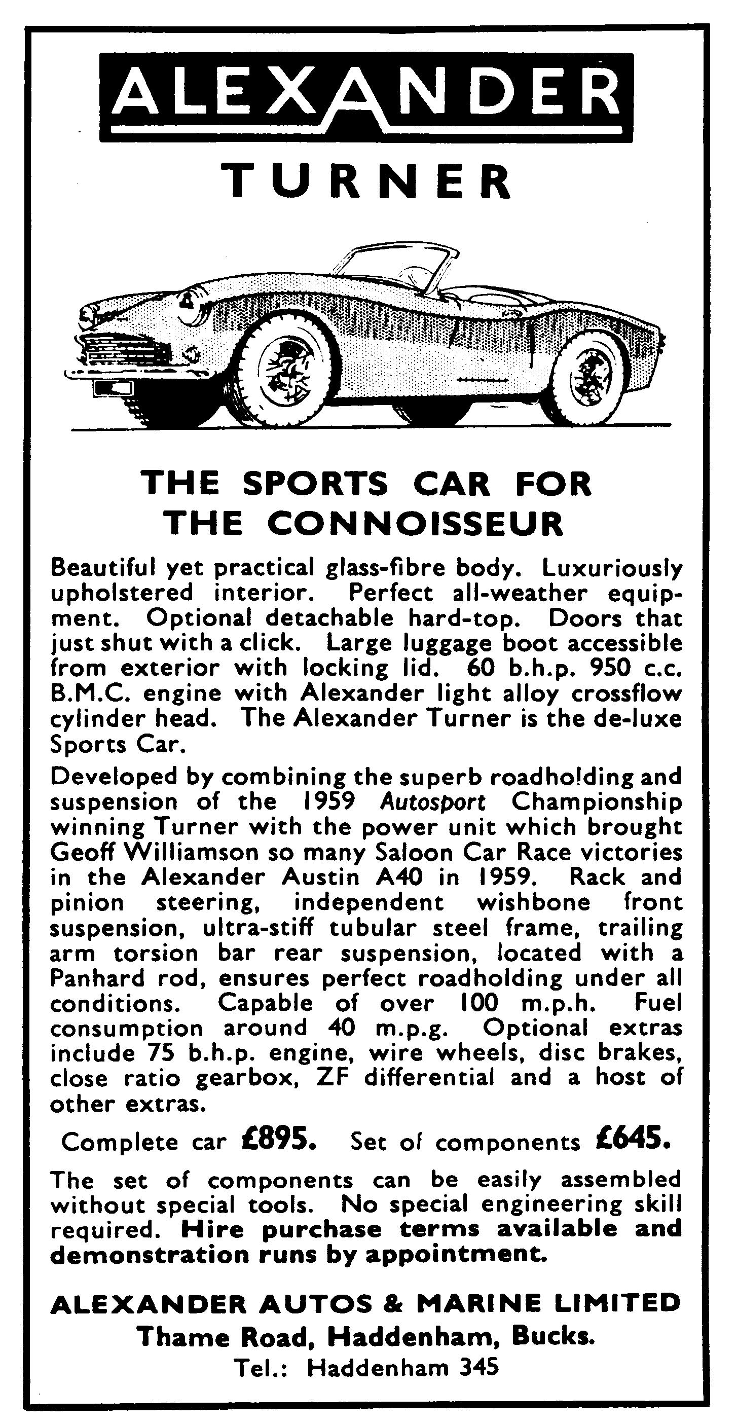
Late 1959 Turner announced the arrival of its redesigned 950 Sports model with a new full-width grille, curved windscreen and smoothened rear. At the same time, Michael Christie, MD of Alexander Engineering informed the press that they would become the new distributor of Turner Sports Cars for Southern England. Mackenzie decided that Alexander should tune the standard Turner, not only because they delivered the car, but also because of the longstanding relationship between Mackenzie and Fred Hillier, Alexander’s “Chief Mechanic”. Fred Hillier was a Senior NCO Instructor at the RAF Apprentice School at Halton and he had prepared and driven the “Schools” Tojero with Climax FWA engine for several years before joining Alexander Engineering after his retirement from the RAF.
Mackenzie made a deal with Michael Christie to race an Alexander-Turner for the 1960 season, the chassis and (BMC-A) engine of which would be prepared by Fred Hillier and the chaps from Alexander after delivery by Turner. The car, a Turner 950 Sports registered 208 JJH on 21 March 1960 in Hertford, had to fulfil the Appendix J regulations, which is why the famous Alexander light alloy cross-flow cylinder head could not be used, much to the disappointment of “businessman” Michael Christie.
The entry list for Class A (up to 1000cc) in 1960 showed sixteen names of which five drove an Austin-Healey Sprite, nine went this year for the fashionable Turner 950 Sports, with one Berkeley B 105 and one Fairthorpe Electron. Well-known names like J.H. (Paddy) Gaston in a special-bodied Sprite and F.R. (Bob) Gerard in a Turner 950 were mixed with drivers whose names only a few enthusiasts nowadays can remember. As can be seen from the entry list, the engine most commonly used was the BMC-A 948 cc in various forms of tuning. Most of them were bored out (+ 0.060″ or more) to increase the capacity to a value just within the 1000cc class. The exceptions were the air-cooled 2-cylinder 692 cc Royal Enfield in the Berkeley and the 948 Standard-Triumph engine (Alexander-tuned, by the way) in the Fairthorpe. Remarkably, there were no Ford engines used at all in this class, though in a few years’ time this would be the engine to beat. But this season, as in the previous years, it would be a “close racing” battle again between Sprites and Turners, having the same engine though a totally different chassis lay-out.
We have to note that there were actually two races on Easter Monday: next to the one in Mallory Park organised by the Nottingham Sports Car Club, there was the one organised by the British Racing and Sports Car Club at Brands Hatch. The latter had a “fatal attraction” at Paddy Gaston with his Sprite deciding to join this race instead of Mallory Park. Paddy (who had made a living out of racing, modifying engines and selling tuning parts from his premises at Richmond Road, Kingston-upon-Thames) was rather unhappy in his first outing, rolling his Sprite on the eighth lap, badly damaging the car but escaping himself with only some bruises. Paddy Gaston, the previous year’s team-mate of Ken Mackenzie, would become Ken’s biggest rival this year, in spite of his unhappy start and his missing the following race.
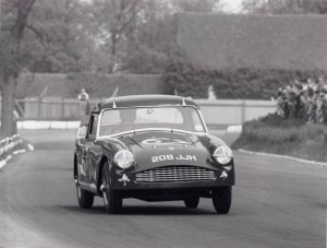
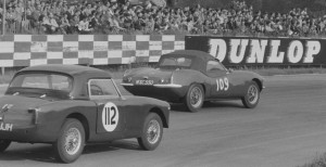
So different was the season’s start for Ken Mackenzie! On the 1.35-mile-long Mallory Park circuit, car and driver seemed to be unbeatable that Easter Monday. The preparation by Alexander was immaculate and Ken, in spite of the early rise, showed his skills in beating all the other Turners. It was pure delight: winning 208 JJH’s maiden race goes against all general belief that a car has to be developed over a couple of races before being able to compete effectively. It turned out to be a true Turner race, with Turners finishing in the first five places. Was this the way the season would turn for Ken Mackenzie and his Turner?
No, definitely not. The second race of the season was organised by the Maidstone and Mid-Kent Motor Club on Saturday 30 April at Silverstone. Again, at the beginning of the 20-lap race it looked as if nothing could beat Ken Mackenzie and his Alexander-Turner, leading the pack of Sprites and Turners. But then, on the fourth lap, he had to quit the race because of a broken weld in the throttle pedal! Delight and misfortune are so very close in racing, as Mackenzie experienced once more. The race was won instead by “good old” Bob Gerard, leading five other Turners. The Championship placing after two races were headed by Simon Scrimgeour, being the steadiest in finishing.
May 8, 1960 Mallory Park
Mallory Park, the third race on 8 May saw the return of Paddy Gaston, only 3 weeks after his accident at Brands Hatch. The dominance of Turners had gone with Paddy Gaston in his Sprite leading the field from start to finish in spite of whatever Ken Mackenzie and Bob Gerard tried to do with Mackenzie ending 2nd in Class. It must have been an extremely well-prepared car and a skilled driver to beat the Turners, since all the other Sprites ended far back in the field.
The fourth round brought Mackenzie and friends to Snetterton, the 2.7-mile-long circuit in Norfolk. Again it was Paddy Gaston who dominated the race, with the Turners battling between themselves for second place. David Pritchard even applies the term “splendid duel” covering that part of the race for Autosport. Behind Gaston, it was Bob Gerard again taking second place. For Mackenzie life was hard; half-way through the race he had to give up with no clear cause mentioned. So far, two finishes and two mishaps for Mackenzie, losing points in the Championship on the others.
 Martini 100 at May 21, 1960
Although not part of the Autosport Championship, Ken Mackenzie took part in the Martini 100 races on May 21st at Silverstone. And he did well, finishing second in Class right behind Jan van Niekerk in his GSM Delta.

On Whit Monday, 6 June, two races (both qualifying for the Championship) had been organised with the result that in both races only a few participants in the A Class showed up, not contributing to the overall excitement of the spectators. At Mallory Park only five Class A cars started in a race that was won by George Morgan in his Turner, in fact beating three other Turners. Ken Mackenzie decided to head for Goodwood (probably because Gaston went there and it was somewhat closer to his home in Northwood) where the B.A.R.C. had organised a 20-lap race on the 2.4-mile-long circuit. Because there were so few Championship participants, the organisers had allowed others to join the race as well, meaning that even a Jaguar Mk II saloon was regarded a Sports Car that day. It still turned out to be a crazy fight with the cars of Mackenzie and Marriot touching each other in Woodcote Corner. It did not help because Gaston finished first, well ahead of the others in Class A, with Mackenzie taking fourth place.
Next came Snetterton: on June 19th Mackenzie achieved 3rd place overall and 2nd in class with a fastest lap time of 2:04,0 and an average speed of almost 80 mph but beaten by Bill Moss in a Marcos GT (a.k.a. the ‘Ugly Duckling’) and Robin Bryant in another Turner.
![clip_image002[4]](http://www.bobine.nl/turner/wp-content/uploads/2013/06/clip_image0024_thumb.jpg "clip_image002[4]")
As the next race would only be at the end of July, Mackenzie decided that there was plenty of time to take his Alexander-Turner “overseas”. Dunboyne, County Meath, Ireland, was the setting for an annual race weekend, this year sponsored by “Messrs. Martell & Co., Cognac”, a contest in which Mackenzie had taken part before with cars such as the MG A. The Leinster-Martell meeting of Saturday July 9 actually consisted of two events, the Holmpatrick Trophy Race and the Leinster Trophy Race, where the organising committee would decide in which race a car would participate, simply on basis of their opinion as to whether a particular car could lap the Dunboyne Circuit at 75 mph average speed! The Alexander-Turner therefore would take part in the Holmpatrick Trophy Race. Saturday 2.55 p.m. saw the start of this 15-lap, 60-mile race. Many competitors had used the opportunity to practise on the Thursday and Friday night before. Not so for Mackenzie who consequently had to fight his way through the entire field after the start. The field consisted of a mixed bag of all kind of different cars and engines capacities, like Austin Healey Sprite, MG TD, TR 3 and even a Fiat Special. It would become a very exiting race between W.D. Lacy in a TR 3 and Ken Mackenzie in the Alexander-Turner. One would think that this could hardly be called a fair competition, but amazingly the small Turner (998 cc) was a real threat for the bigger TR (1991 cc). Until on the 10th lap fate struck and Mackenzie had to withdraw with “mechanical trouble” and Bill Lacy could finish the race without any problem.
![clip_image002[6]](http://www.bobine.nl/turner/wp-content/uploads/2013/06/clip_image0026_thumb.jpg "clip_image002[6]") Mackenzie battling at Dunboyne, Ireland
Mackenzie battling at Dunboyne, Ireland
Mackenzie himself reports twice on this event. In a letter to Autosport of August 1960 he writes: “The facts are that on the 10th lap, when leading Lacey, the eventual winner, and lapping at over 80, my radiator was holed and I lost all the water and retired with a resultant cracked cylinder head. In fairness to the car, which was the only other entrant in this race besides the eventual winner to lap at over 80, I would like this to be put across.
In another letter of October 1985 to Motorsport Mackenzie looks back: “This car was very successful in the Autosport Trophy, National and some International events, only not being placed in two out of 16 races and these due to minor mechanical problems. The worst being the Irish Holmpatrick Trophy, lost four laps from the end by a holed radiator, the Turner being timed at 108 down at the back straight, the second losing an Autosport trophy class win by a broken throttle linkage at Silverstone”
About the 8th race of the season we can be rather short as it was cancelled. On 31 July at Mallory Park there were too few entries from Classes A and C, even if they were combined in one race. Nevertheless we have to mention this race as it saw the first performance of another famous Turner, the Pat Fergusson-driven Turner-Climax, better known as “Tatty” Turner. This car, built by Allen Smith who also tuned the 1216 cc Coventry Climax FWE engine, was not yet homologated and just took part as a try-out in the Class B race. Fergusson would gain great successes in 1961 with this car as did Warwick Banks in 1962; both men won the Autosport Championship in their classes.
Ken Mackenzie still had every possibility to win the 1960 Championship himself with, after eight races, a second place in Class A with 23 points, just behind Paddy Gaston leading his class with 28 points. With (officially) one more qualifying race and the “grand finale” to go, it was becoming exciting in Class A. Managing Editor of Autosport, Gregor Grant, was of the opinion that participants of Class A and C should have an equal chance (as Class B) to win the overall Championship and therefore tried to arrange an extra race to replace the cancelled one of August 31.
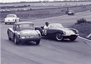
Snetterton om August 6th was the venue of the ninth race and a very special race it was! Combined with the last qualifying race for the Autosport Series Production Sports Cars Championship, Saturday August 6th saw the final of the 1960 Autosport World Cup for GT cars between the teams of Holland and Great Britain. The Class B race took place together with heat 1 and Classes A and B with heat 2 of this GT final. David Pritchard was full of praise for what he saw that afternoon: “Superb Snetterton” was the ringing title of his first-class story in Autosport.

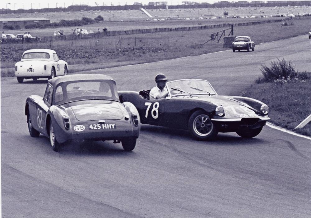
 Left: Ken Mackenzie at Snetterten;. Right: Mackenzie leading Bob Gerard in his Turner JU 5
The second heat saw an interesting battle between such cars as the Porsche S90, the Lotus Elite and the MGA Twin Cam, remarkably closely followed by Paddy Gaston in his special-bodied Sprite. That Gaston finished fifth overall in this race indicated once more the excellent qualities of car and driver. Ken Mackenzie did quite well that afternoon, finishing third in class behind Gaston and Gerard, nevertheless losing 4 points on Paddy Gaston who now led the Championship ranking with a safe 9-point lead, with Ken Mackenzie and Bob Gerard in equal second place.
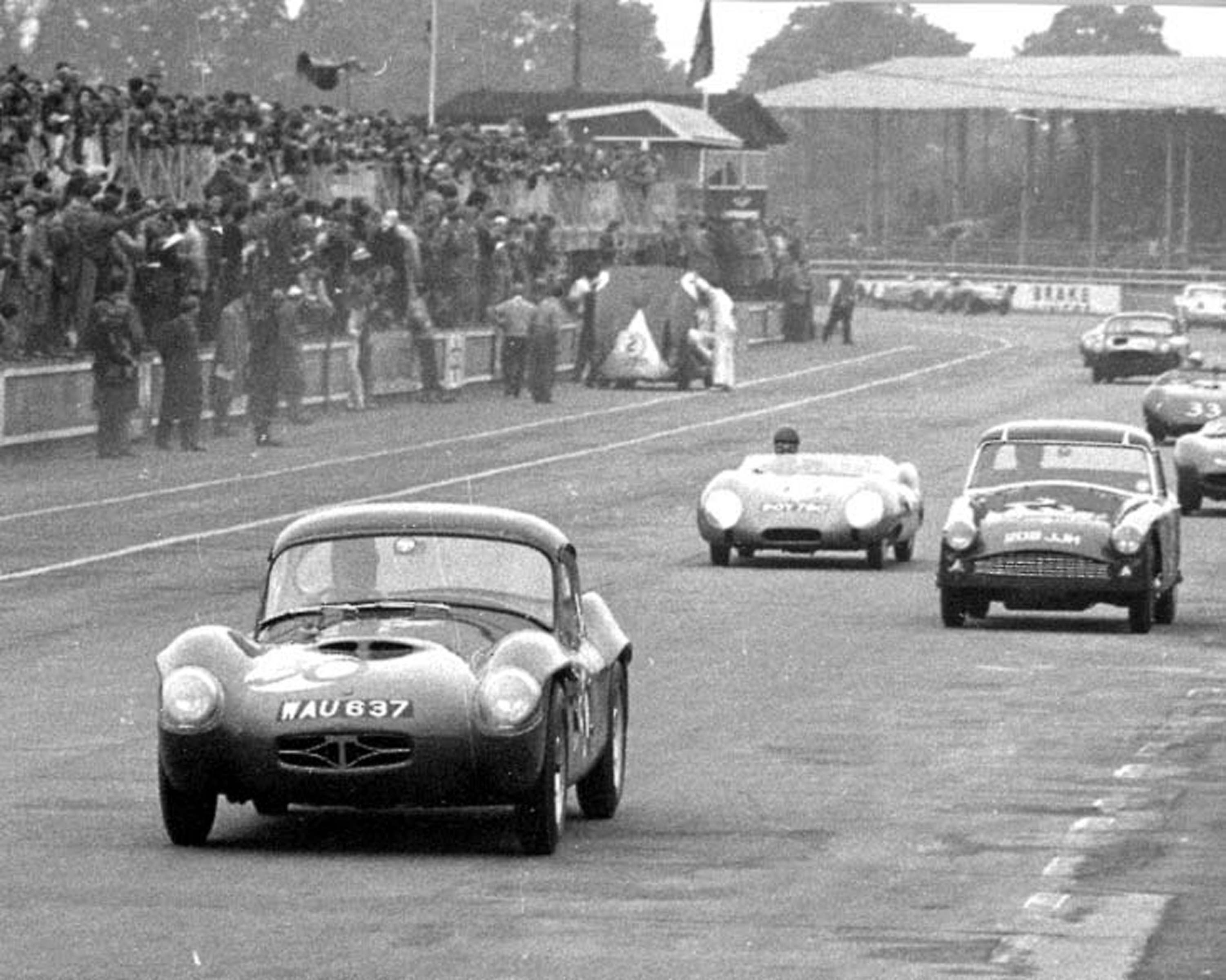
 Mackenzie ahead of the rest at Aintree August 7, 1960
Managing Editor of Autosport, Gregor Grant, managed indeed to organise an additional race for Class A to make up for the missed opportunity of earning Championship points on July 31. Just a day later, August 7, during the BARC meeting at Aintree, the 3-mile-long racing circuit near Liverpool, the rivals in Class A met again. The fact that Paddy Gaston could not participate due to mechanical troubles that came to light just before the race was a tremendous opportunity for Mackenzie (as well as for Gerard, of course) to get closer in points. During the first race of the day it was the usual “battle of the Turners” with George Morgan leading in front of a MGA Twin Cam and the other Turners, including Mackenzie who finished fourth in class and (worst of all) behind Bob Gerard who now took over second place in the Championship. One could say without exaggeration that there was a real “Turner” dominance that afternoon in Aintree; since Gaston did not start, the Turners had no problem in taking the first four places in Class A, only then followed by a Sprite and a Fairthorpe Electron.
![clip_image002[8]](http://www.bobine.nl/turner/wp-content/uploads/2013/06/clip_image0028_thumb.jpg "clip_image002[8]") The Three Hours of Snetterton preview
The Three Hours of Snetterton preview
Since Mackenzie’s race was so early in the day, he found there was plenty of time for another race later in the day. In a Sports Car race for up to 1000 cc overhead valves and up to 1200 cc side valve engines (note the creativity of organising committees in forming competitive classes) Ken managed to finish third overall behind a DRW Ford and a Lotus 7 with Austin engine, outperforming a TR2 and 3, as well as a Twin Cam MGA.
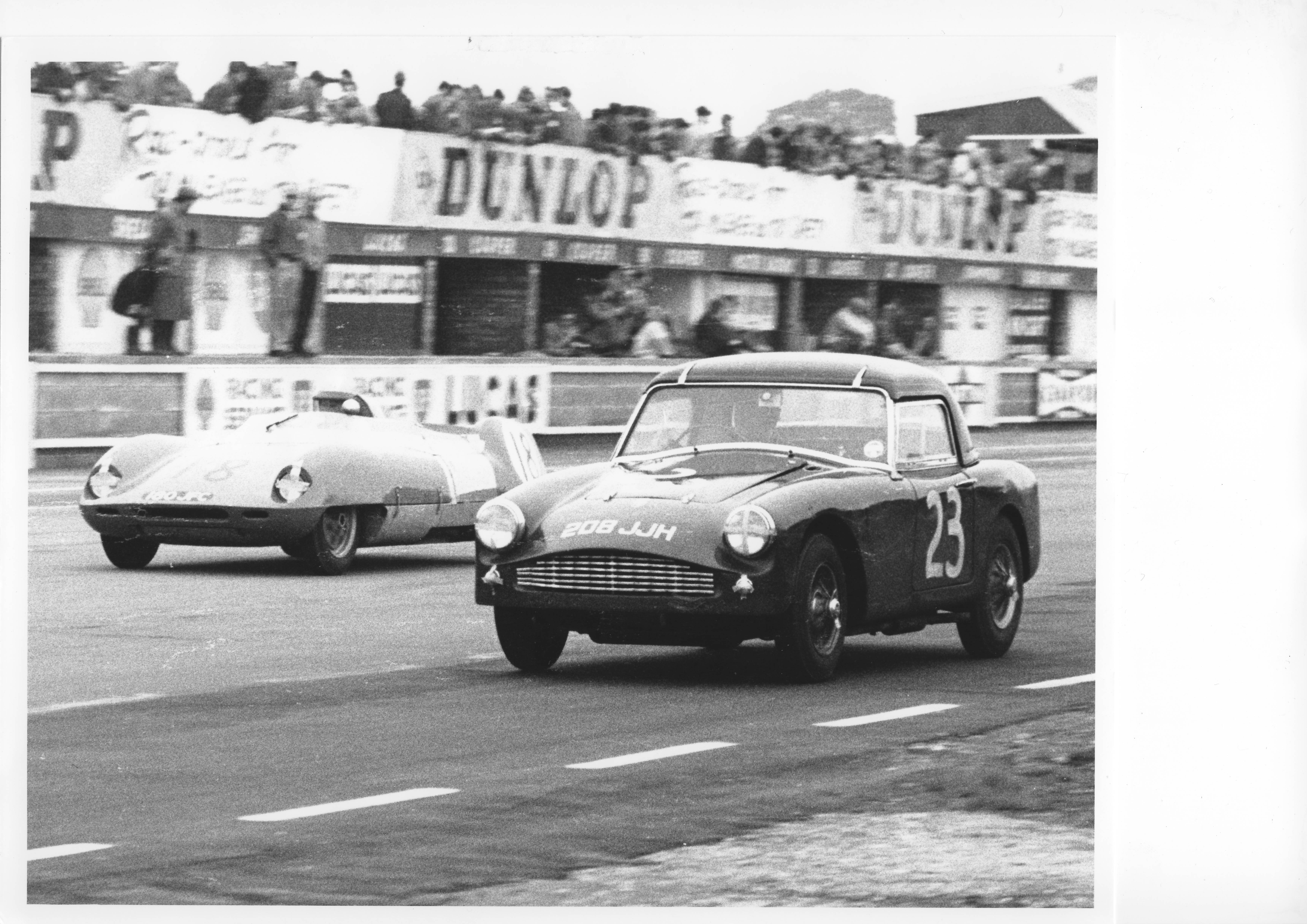
The “Three Hours” of Snetterton formed for the fourth successive year the final of the Autosport Series Production Sports Car Championship. This unique racing event (part day and part night; the only one in the UK) holds a very special place in the heart of many a driver. The ambience is reminiscent of Le Mans: the excitement, the crowds, the headlamps peering through the darkness, the refuelling, even the start itself has that “nostalgic” atmosphere of racing at its best. And besides that, a wealth of points could be gained (double points during this final) meaning that everything is still open.
In the preceding weeks, Autosport had presented the list of final participants and contemplated the chances of the various rivals. A full-page picture gallery of the drivers still in the race for Championship gave an extra dimension to the upcoming event. Among the ones pictured was Ken Mackenzie, who regarded this as a tremendous reward for a beautiful season, no matter what the final “Three Hours” would bring. A reward for skill and perseverance of the driver and, most of all, for the quality of the Alexander-Turner and those that had prepared the car.
On many occasion, before and after, Ken Mackenzie expressed his admiration and respect for that “little” car; “in fairness to the car”, as he once said.
“Those of us who raced Turners, of whatever mark or power, enjoyed some classic sport, safe, reliable and competitive,” were his words when he looked back in Motorsport 15 years later.
What should have been the “culmination of the season” was in fact utterly disappointing for Mackenzie. The “Three Hours” of Snetterton started at 5.30 p.m. precisely and for almost 2 hours things looked so good for the Alexander-Turner. Then, at 7.15 p.m. Ken had to retire after 50 laps because of an “almost total absence of gears”. Mechanical failure meant that the end of the season had come, prematurely but inevitably.
![clip_image002[10]](http://www.bobine.nl/turner/wp-content/uploads/2013/06/clip_image00210_thumb.jpg "clip_image002[10]") Turner add referring to racing successes at end of 1960 season
Turner add referring to racing successes at end of 1960 season
The 1960 Championship Table shows Ken Mackenzie in tenth position, the overall Championship being won by Chris Summers in a Lotus Elite, competing in Class B. Since Paddy Gaston (AH Sprite) and George Morgan (Turner) qualified with their second and fourth place overall for a special Championship Award, Ken Mackenzie moved up in Class A to third place behind Bryant (Turner) and Gerard (Turner) to gain a Trophy to remember this fine season for ever.
 Brands Hatch October 16 1960
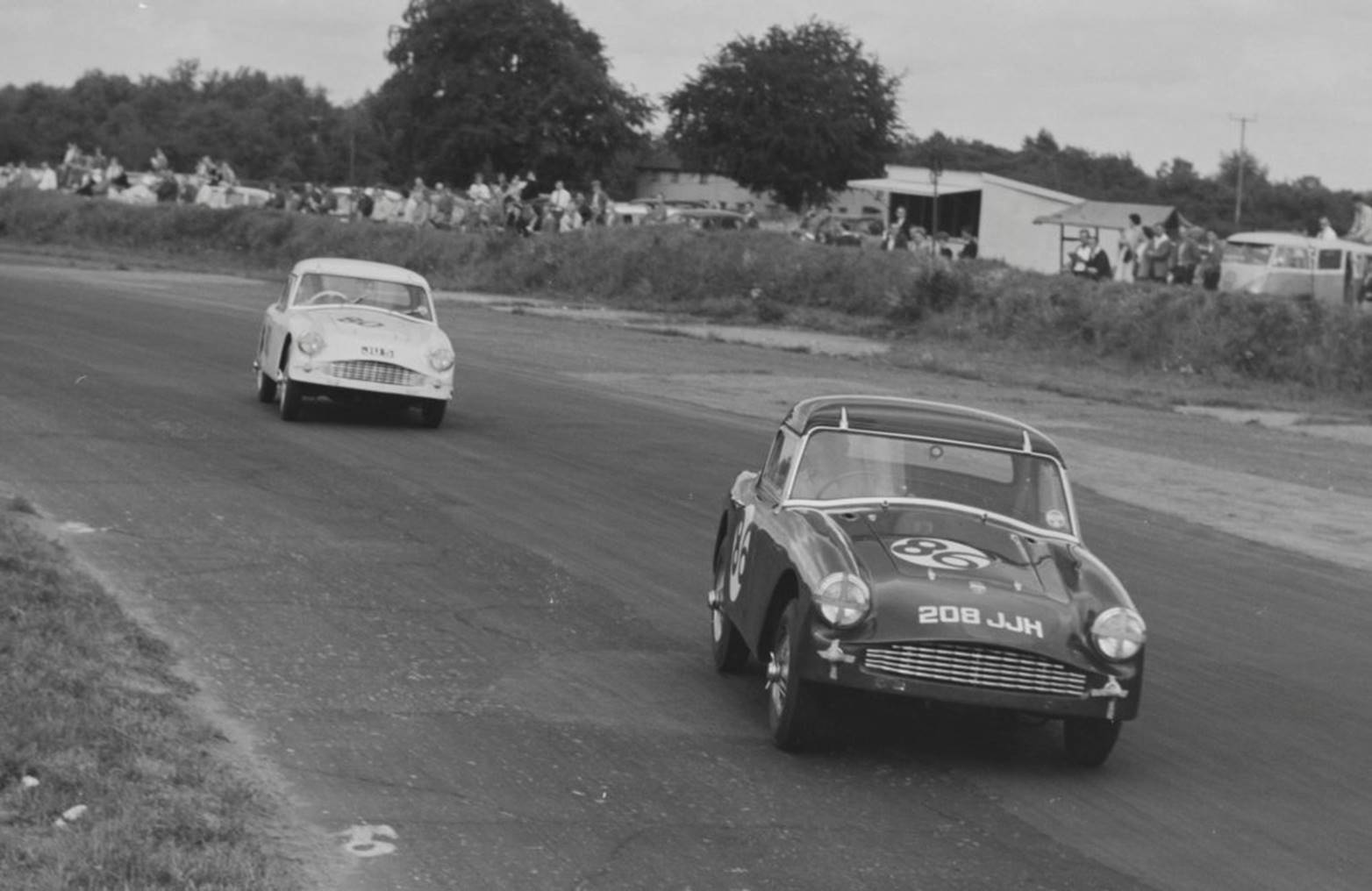
To close-off the season Ken participated on October 16th in another race at the 1,24 mile long Brands Hatch circuit, in which he ended 1st in class with a fastest lap 1:07,4 or 67 mph: a worthy closure of his first season in the Alexander-Turner!
BK
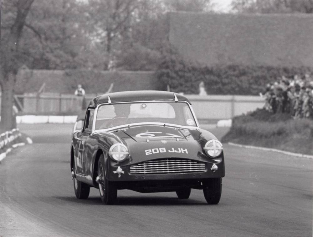
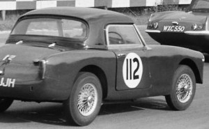 208JJH at Brands Hatch in October 1960
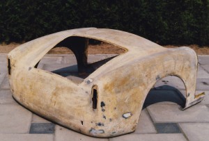 Rear body of 60-307 with original position of external fuel filler still visible
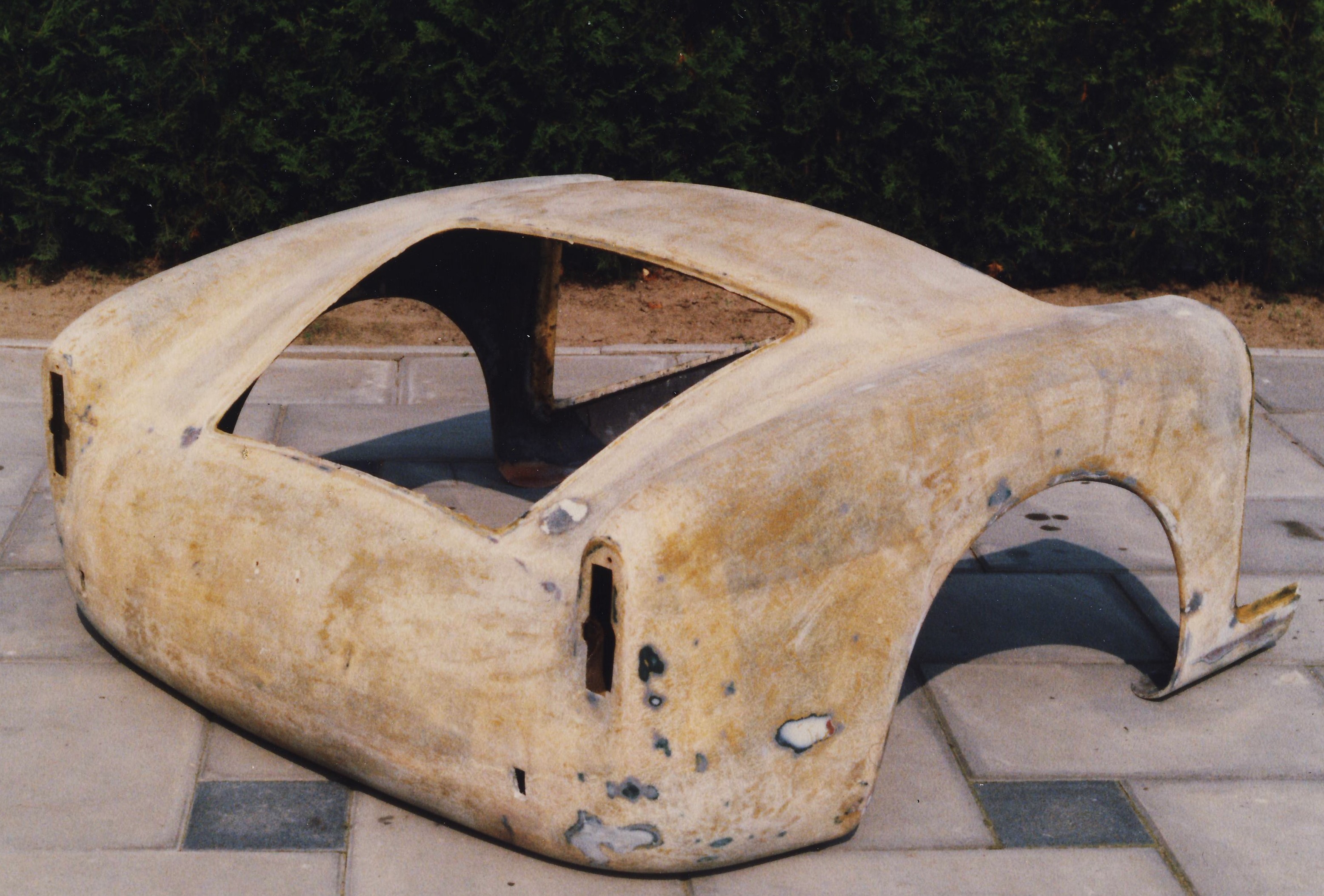
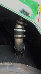 New filler pipe construction
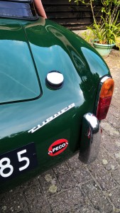 Final result; compare with original photo.
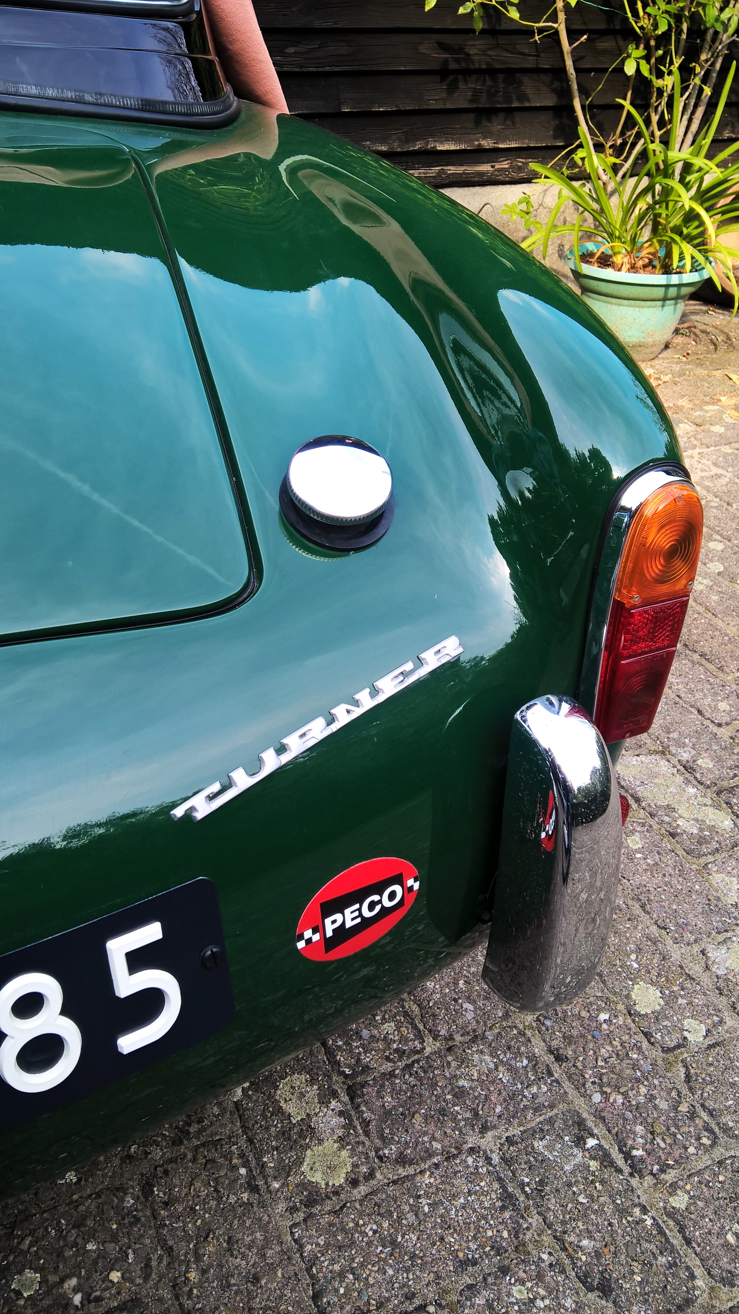


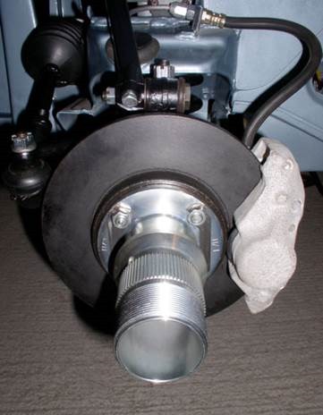 Special splined hubs for Girling Type 10
![clip_image002[4]](http://www.bobine.nl/turner/wp-content/uploads/2014/06/clip_image0024.gif "clip_image002[4]")
![clip_image002[6]](http://www.bobine.nl/turner/wp-content/uploads/2014/06/clip_image0026.gif "clip_image002[6]")


![clip_image002[4]](http://www.bobine.nl/turner/wp-content/uploads/2013/06/clip_image0024.jpg "clip_image002[4]")
![clip_image002[6]](http://www.bobine.nl/turner/wp-content/uploads/2013/06/clip_image0026.jpg "clip_image002[6]")
![clip_image002[8]](http://www.bobine.nl/turner/wp-content/uploads/2013/06/clip_image0028.jpg "clip_image002[8]")
![clip_image002[10]](http://www.bobine.nl/turner/wp-content/uploads/2013/06/clip_image00210.jpg "clip_image002[10]")