Category Archives: 12. Body
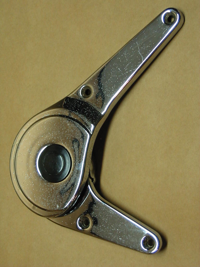
Bonnet stay (hood prop) XK 140 FHC
Leave a reply
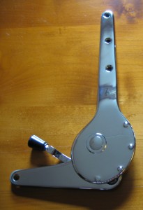
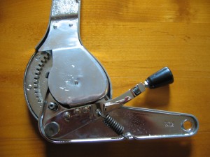
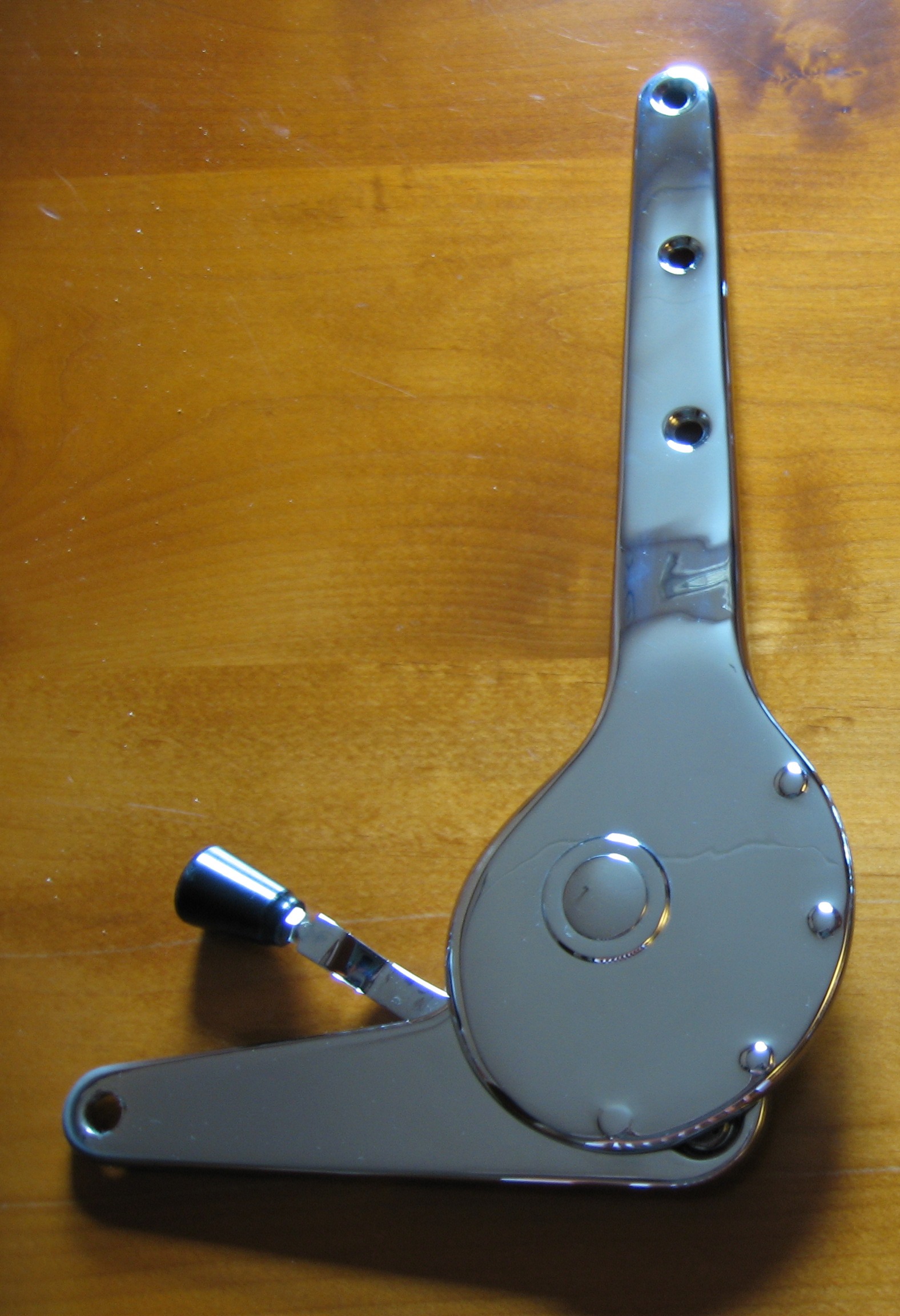
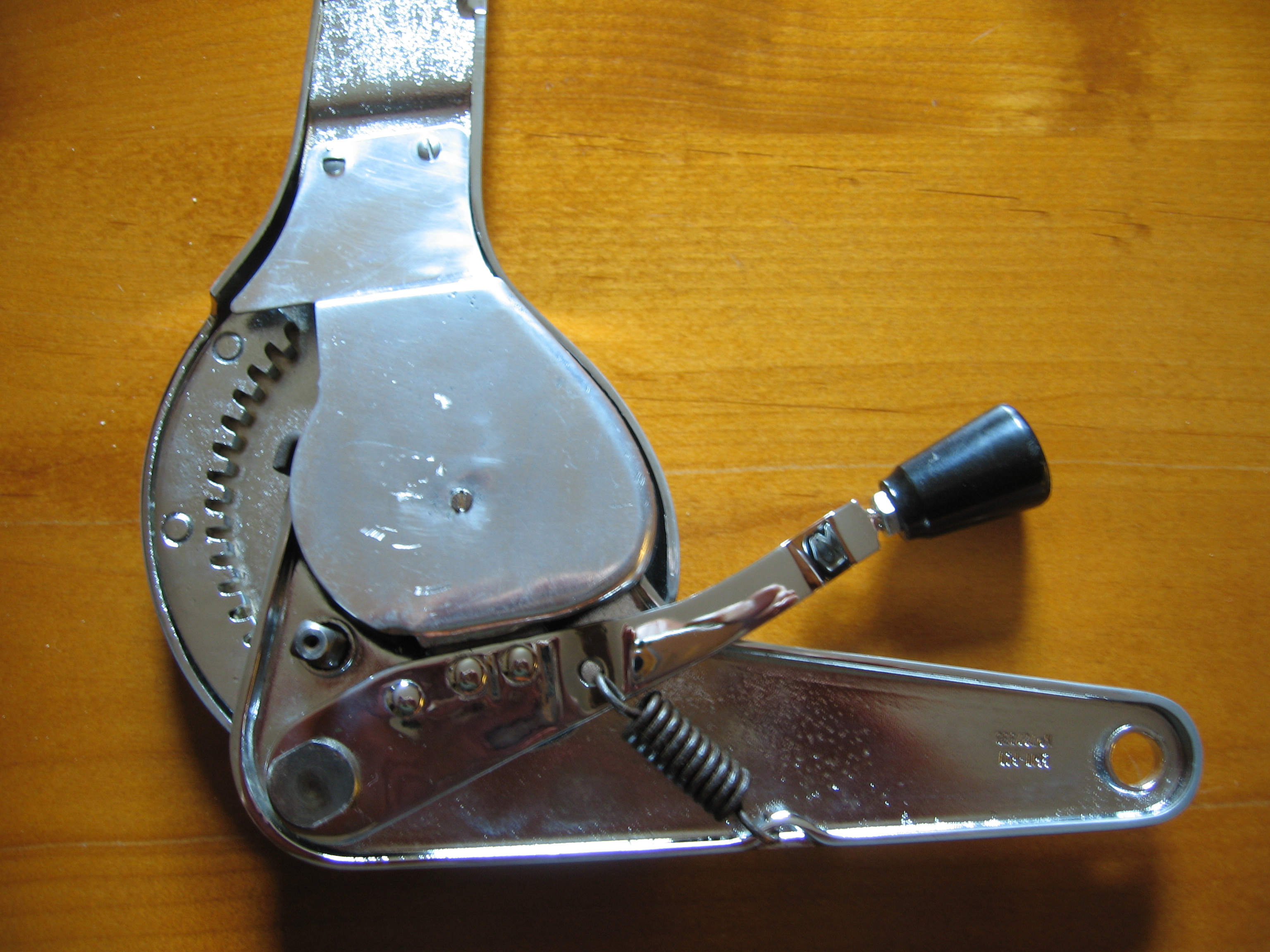
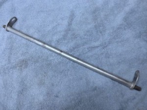
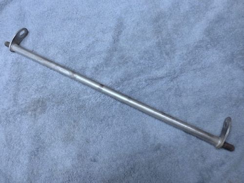
Bonnet stay (hood prop stick) construction for Jaguar XK 140 FHC
The Jaguar Service Parts Catalogue for the XK 140 (FHC) describes the following parts for the XK 140 FHC Bonnet Stay construction:

This construction is different from the one for the 140 OTS and DHC: all parts for the FHC are specific for this model only. The XK 150 is again different.
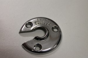
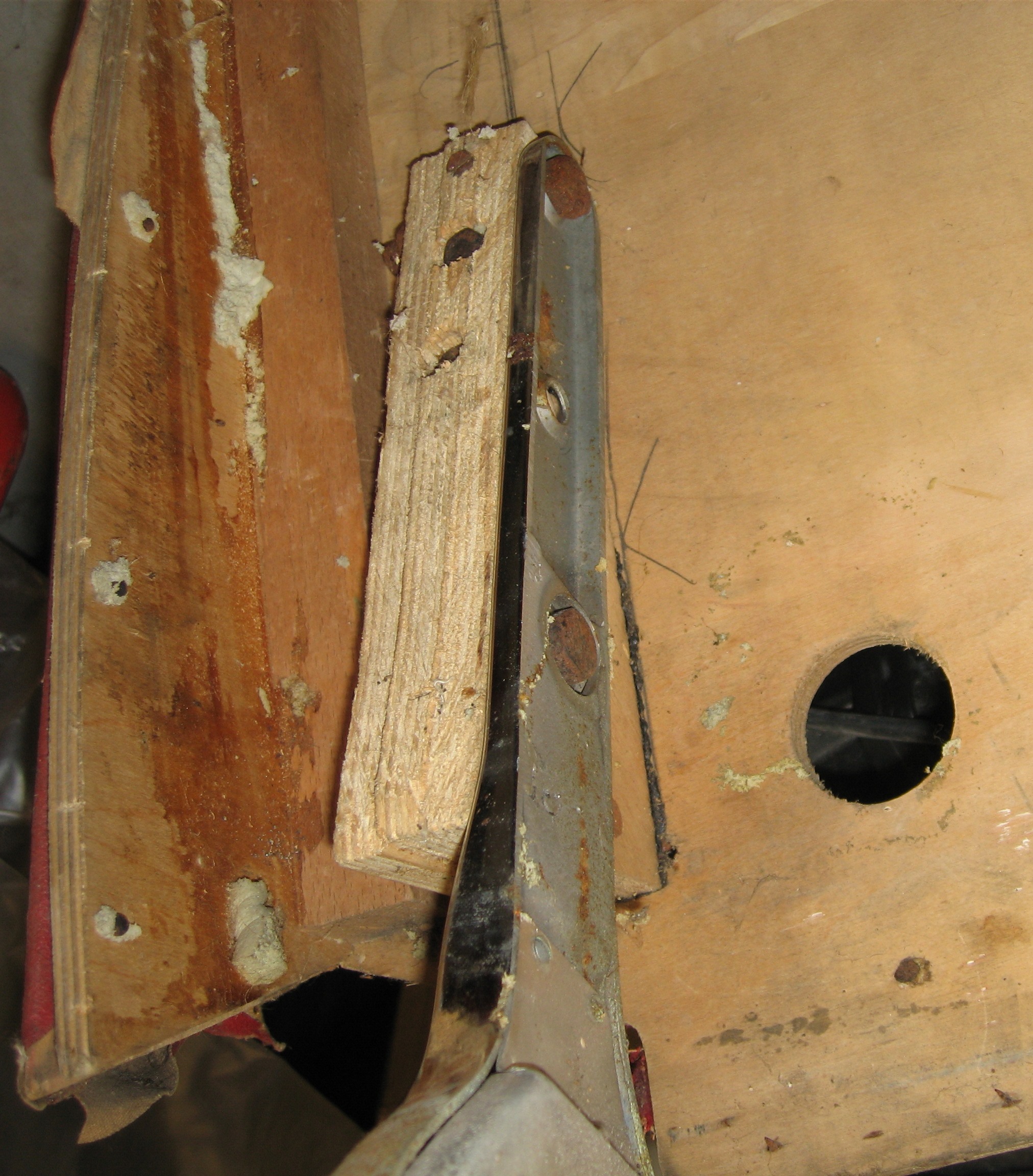
BD.10803 Bracket on Bonnet for pivot
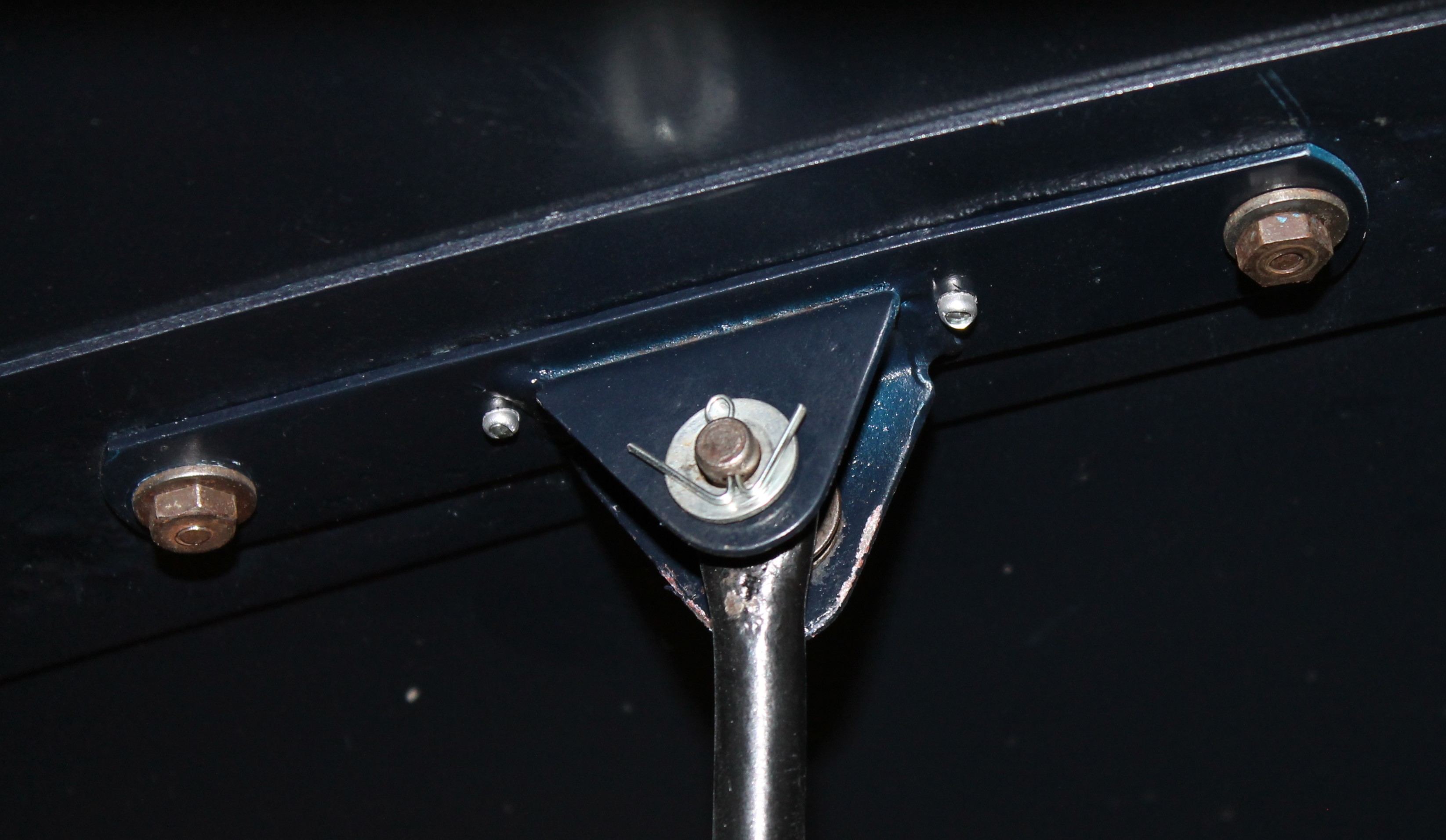
This bracket acts as a hinge for the prop and is attached to the bonnet centre. There are 4 holes in the bracket. The 2 smaller holes near the pivot pin are used for a pop-rivet to hold the Bracket in place (temporarily), while the outer 2 (larger) holes are used for the fixation of the chrome bonnet strip BD9779 over the bonnet and are secured with a nut on the inside. These are the Special Bolts BD.2248 (“hammerhead”) bolts that slide into the chrome strip.
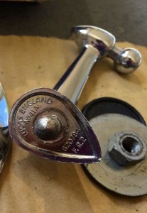
BD.10123 Prop assembly
This prop stick has an overall length of about 27” or 685 mm. Note that the prop is “handed” and should be fitted in a specific way for the “rest” to stay under the correct angle in the Radiator Bracket C.10144.
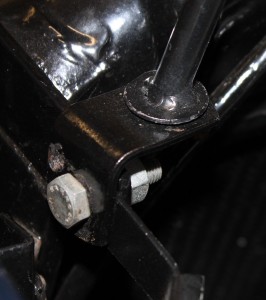
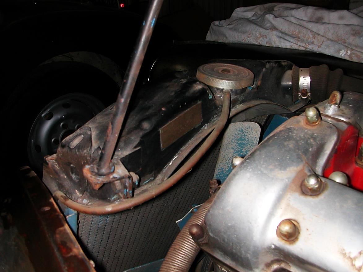
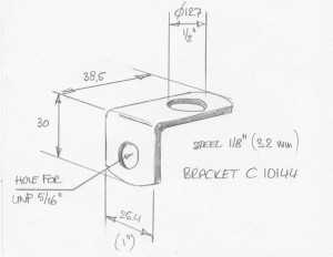
C.10144 Radiator Bracket

 Old (LH) and new (RH) radiator with Bracket C.10144 in place. (Incorrectly positioned on LH photo!)

Although the XK 140 used two different radiators, the Radiator Bracket remained identical but the mounting of the bracket is somewhat different.
 L-shaped bracket is rather simple to manufacture

The early radiator used long “tie rods” with corresponding brackets fixed to the radiator. Radiator Bracket C.10144 is affixed under the 5/16″ UNF bolt used for the connection of the “tie rod”. The later radiator used “tie bars” but the method of fixing the L-shaped Radiator Bracket C.10144 is the same , positioned with the longer part of the bracket towards the centre of the car .
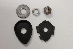
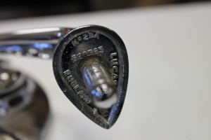
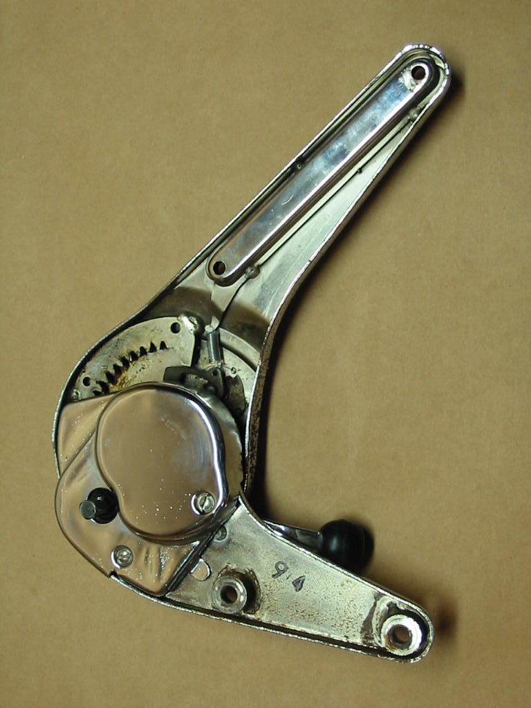
BD.11095 Clip and Bracket assembly on bonnet for prop when not in use

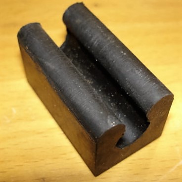
Whereas the prop rest on a clip attached to the inner wing for the OTS and DHC, for the FHC a special bracket is attached to a cross panel on the inside of the bonnet. The rubber, however, is identical for all versions. There is no part number in the XK 140 SPC for this rubber part but some part suppliers use a later XK150 number BD.14943; this (longer) rubber has to be cut to size.
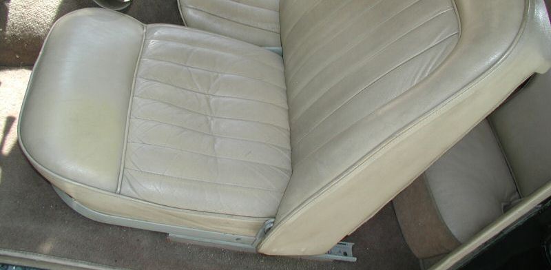
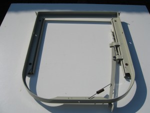
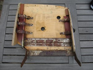
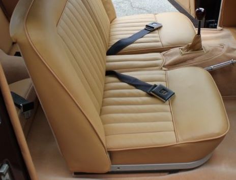
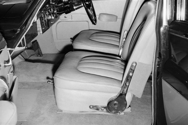
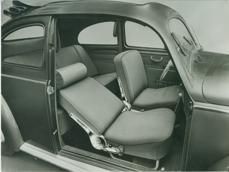
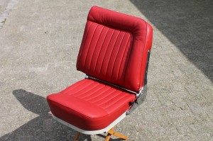
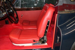
Two types of seat frames for XK 140
Two types of seat frames for XK 140
Introduction.
Not commonly known and also not mentioned in the official Spare Parts Catalogue, the Jaguar XK 140 actually did have two different versions of seat frames over its production life. To be more precise: only the DHC and FHC had a revised construction of the seat base and backrest, whereas the OTS continued unchanged until the production of the XK140 ceased in January 1957.
 Later seat with revised frame: note new hinge partially visible and hole for earlier hinge in frame
The change-over point in production is around the 20th of March 1956 for both the DHC and FHC. It looks like the new tubular backrest frame was based on the new XK150 frame version (and in fact also used for the Mk1 and Mk2) scheduled for introduction only 12 months later.
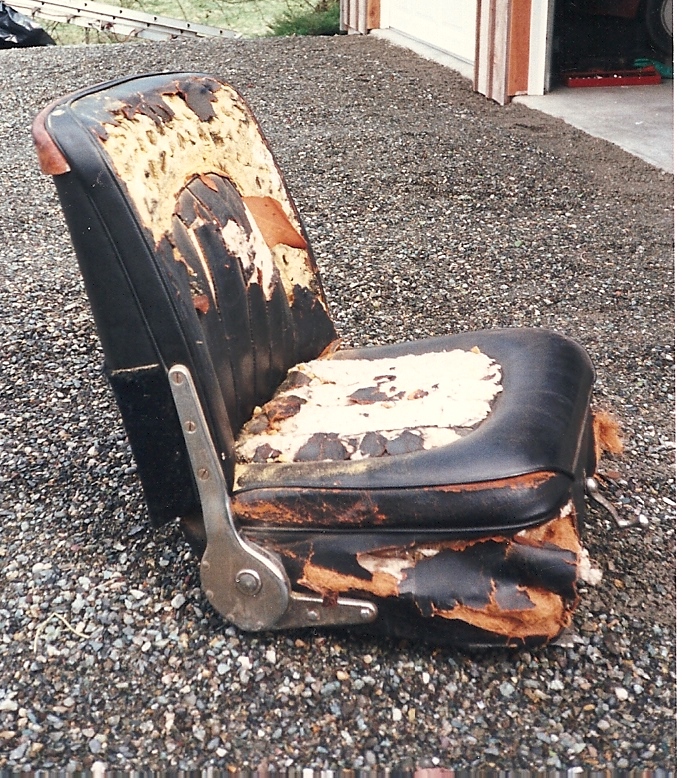
Early seat frame construction.
The Jaguar XK 140 DHC and FHC have always shared their seats but the OTS had a different backrest construction (although it kept the same seat base construction). The early seat frames consisted of a RH and LH steel seat base frame and a RH and LH wooden frame with metal strengthening and hinges for the backrests. The seat base frame had holes (Left and Right) for the hinge pivot bolts (BD3255) and two stops for the hinged backrest. The complete early construction has been well described in the Spare Parts Catalogue.
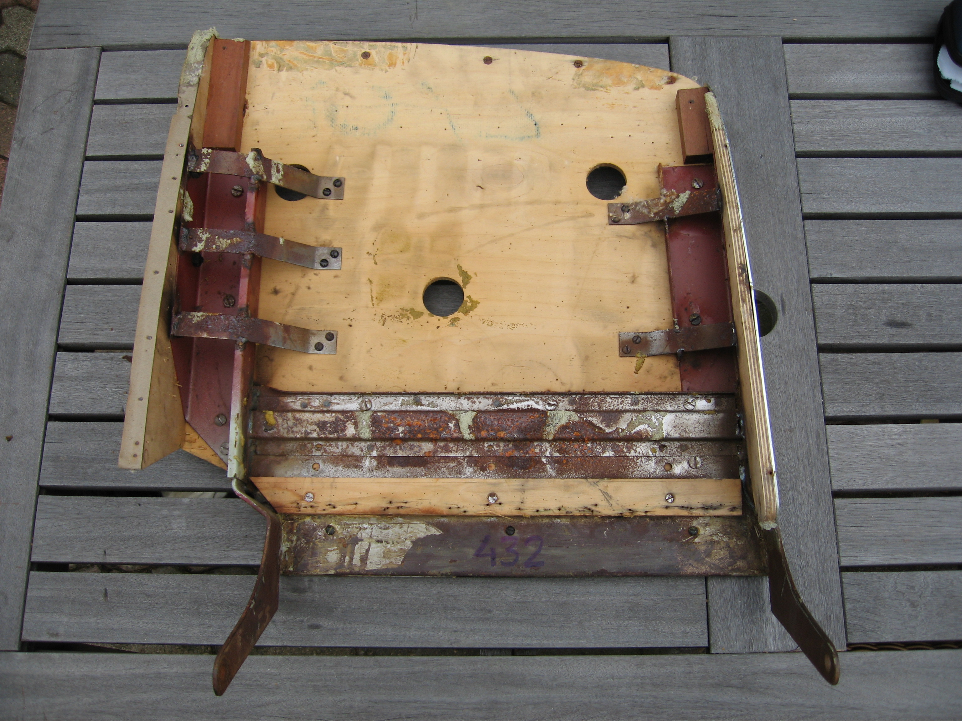
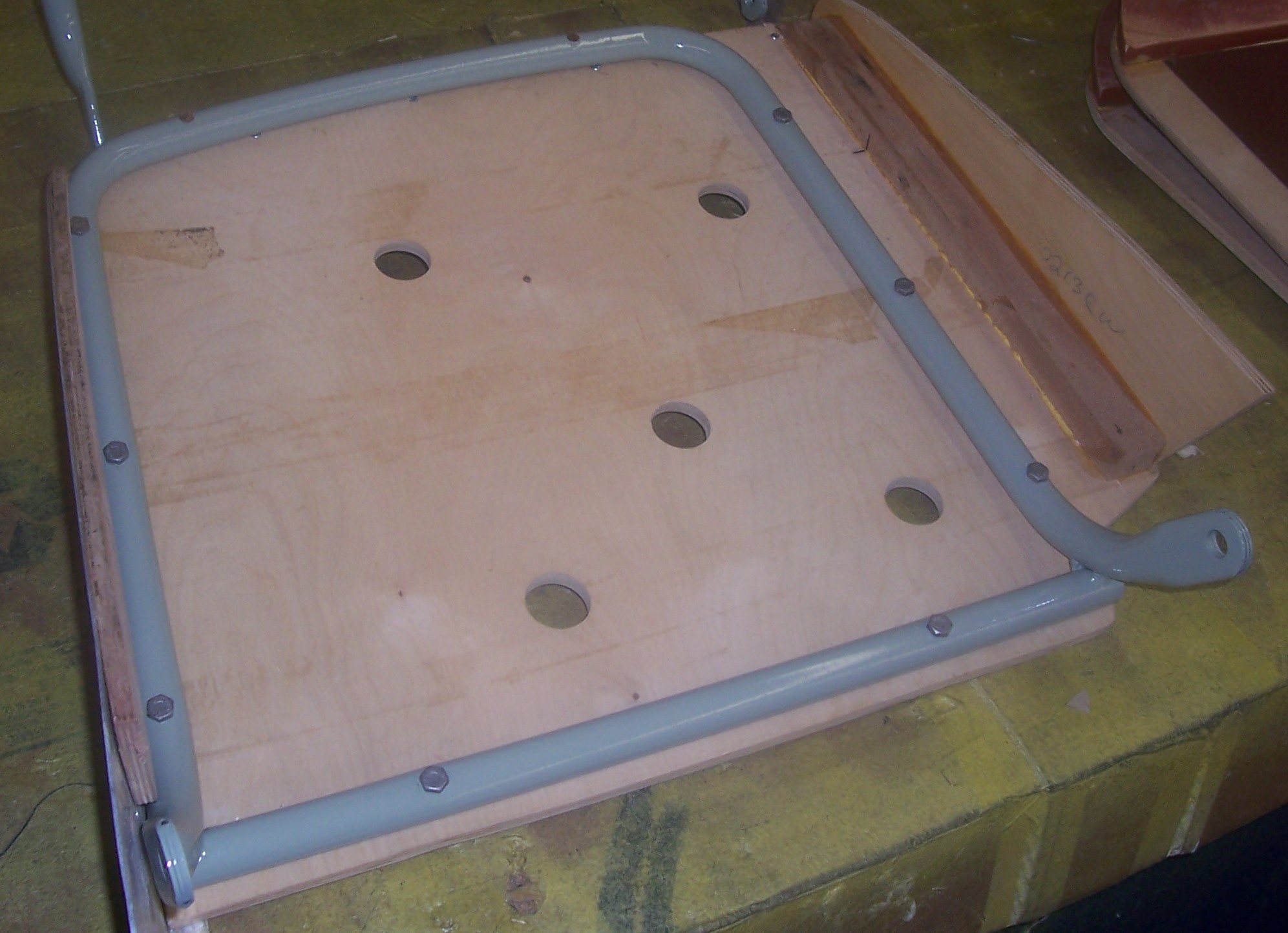
 BD9334 RH seat base frame assembly all versions. Seat pan (aluminium)

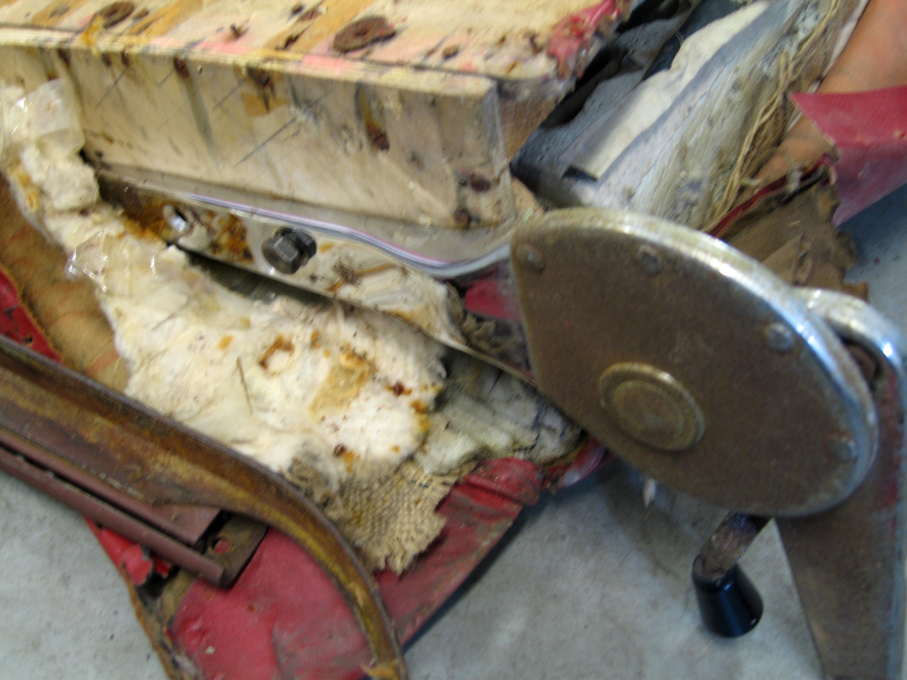
The seat base frame had an aluminium seat pan which was the basis for the “Dunloppilo Latex Foam Cushioning” (F3508) followed by padding and leather upholstery.
 Dunloppilo Latex Foam Cushioning F3508

As can be seen below the early backrests had a fabricated metal strengthening consisting of two sheet metal channels to which the hinges (“dog legs”) had been welded. At the rear and the sides plywood is used, which is the basis for the (“Dunloppilo”) foam rubber cushioning, padding and upholstery.
 BD9617 LH seat squab frame assembly DHC/FHC
Later seat frame construction.
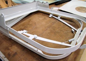
For the second version both the base as well as the backrest changed. The backrest now had a metal frame made from round steel tubing that had been flattened for about 2” at the lower end, forming a flat place for the pivot bolt hole. This change towards tubing is probably led by efficiency considerations, which becomes more clear when we compare early and later backrests (see photos) and more in particular the assembly time required for the early version.
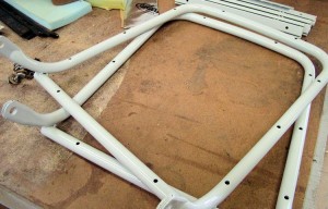
 Later tubular frame for XK 140 Tubular frame with plywood panels (XK150 shown)

As with the earlier model, plywood was used for the rear of the backrest (fixed to the metal tubes) and the sides, supporting the (“Dunloppilo”) foam rubber cushioning, padding and leather upholstery.
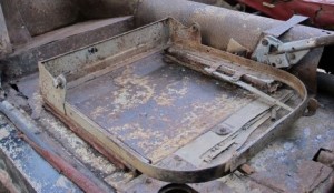 Later seat base frame with higher rear part Original unrestored version


Because the backrest of the seat had changed, the original hinge construction and position could no longer be used and the hinge position had to be changed (about 4” higher and 2” to the rear). A metal strengthening was added at the back of the original base frame (see photo above). Note that the early pivot bolt hole has been kept probably because the early seat base frame was used and modiied. This is also a way to recognize the later seat frame type immediately: the 3/8” hole in the side of the base frame remains clearly visible.
No part numbers have been assigned to this later seat frame type by Jaguar (or at least they have not been published).
Different upholstery for later seat frames
The change in construction of the seat backrest frame also necessitated a change in the upholstery in particular related to the lower hinge part. Some upholstery suppliers therefore ask you to specify whether you have an early or a later XK 140 DHC/FHC seat type.
 Old frame (LH) upholstery with exposed hinge; new frame upholstery with covered hinge

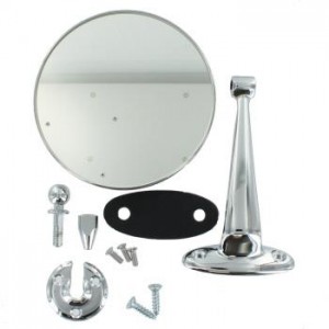
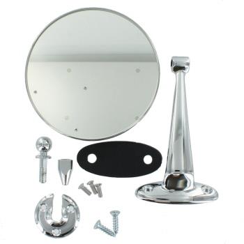
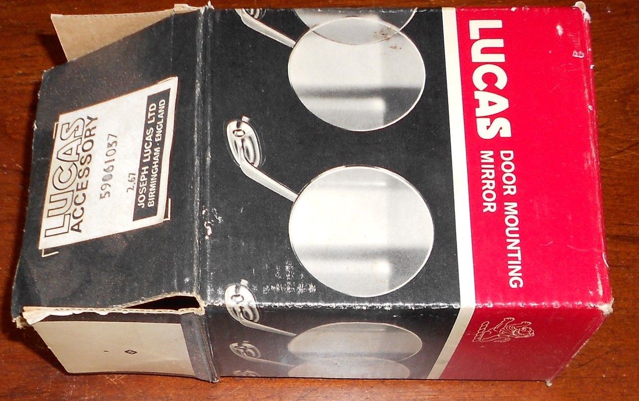
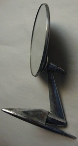
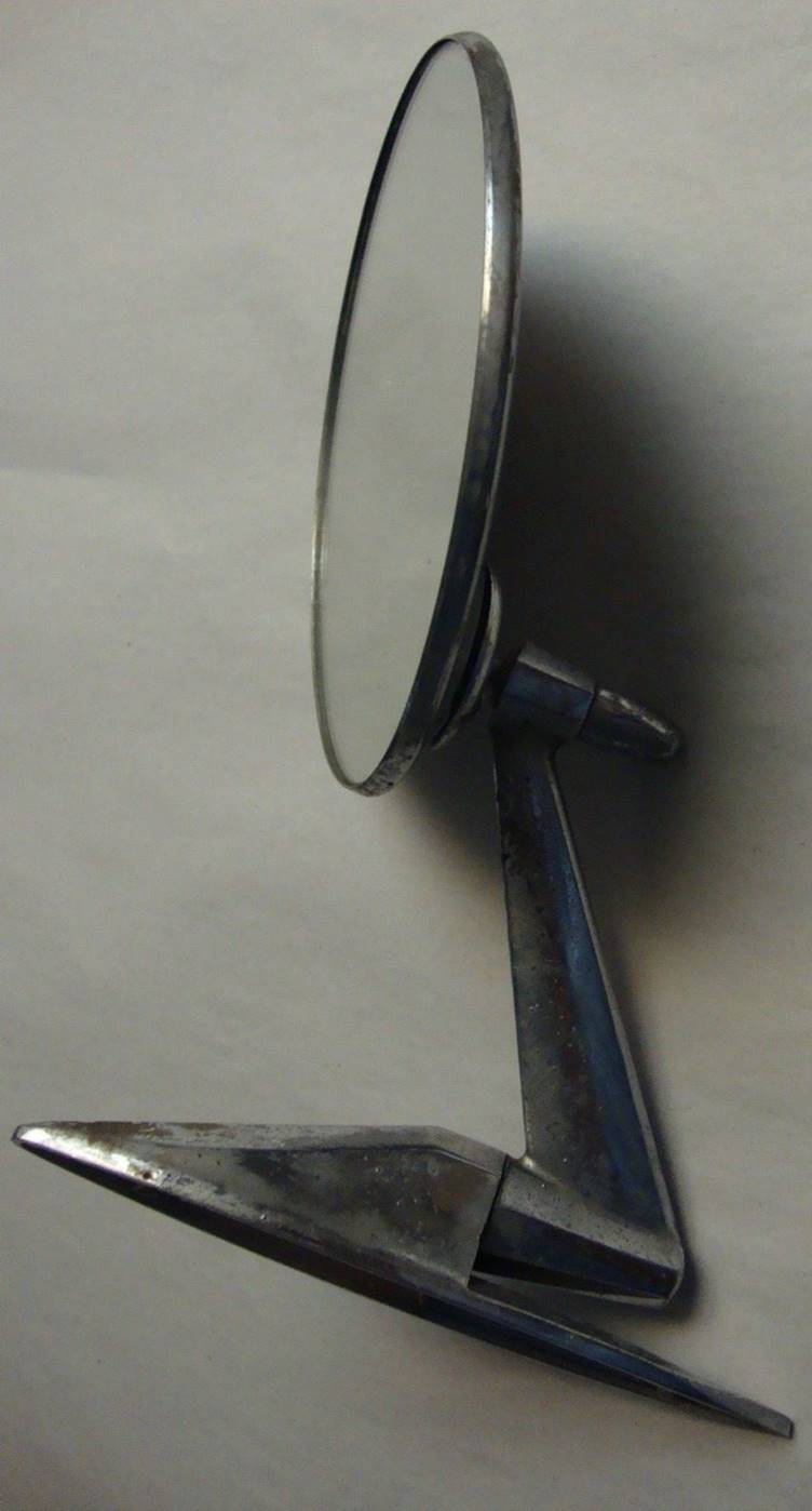
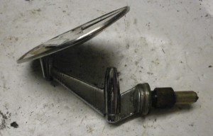
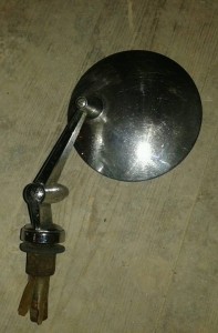
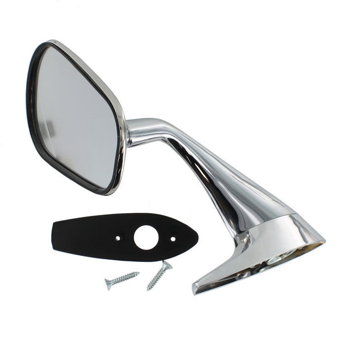
Lucas wing mirrors on Jaguar (’45 to ’70)
Potential suppliers of wing (fender) mirrors
Known for their electrical equipment, Lucas also had a large range of rear view mirrors in their programme from the 1930s onwards. It is therefore logical that Jaguar first had a look at the Lucas mirror portfolio. Next to Lucas there were a large number of other (pre-war) mirror manufacturers like Wingard, Magnatex (TEX), Raydyot, Desmo, and many others. We have to note that in the 1940s and 1950s there were many countries without a legal obligation to have exterior mirrors and therefore these mirrors were only offered as an “optional extra” or even to be purchased by the owner as an aftermarket product. In (some states of) the USA, however, it was necessary to have one exterior mirror mounted at the driver side.
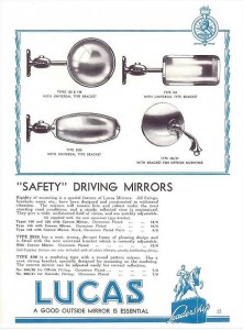 1937 Lucas catalogue; note that Lucas 406 mirror dates from 1937

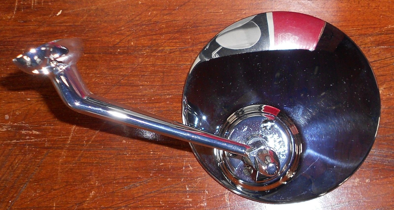
Wing (fender) mirrors for Jaguars: the 406 series with convex glass.
“First generation” Lucas 406
In the mid-Thirties Lucas introduced the “Lucas 406 exterior mirror for mud-wing mounting” which was available as Nearside and Offside version. The 1939 Lucas Catalogue 400B refers to an outer diameter of 4 3/16 inch or 106 mm and lists the following part numbers:
406/29-OS 580.733 406/41-NS 580.736
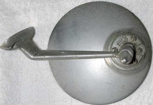
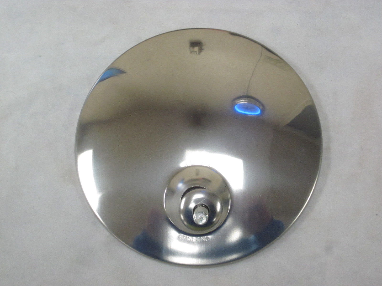
The Lucas 406 series exterior mirror is mounted with a single bolt (5/16” BSF) through the front wing. It has a chromium plated round mirror head, and was available with convex glass only. The mirror head is adjustable and is secured by a clamp using 3 screws. This implies that all Jaguars manufactured before the mid sixties could have convex mirrors only. Flat glass mirrors are a later addition or replacement.
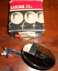 Original 406/29 convex glass mirror and box

The Jaguar Mark V parts catalogue lists the Lucas 406 mirror 580733/A for RHD and 580736/A for LHD. Apparently only one side was supposed to get a mirror installed on the wing above the front wheel. We also find the description (supporting this) that some Jaguars only had an “O/S mirror” (off side or passenger side).
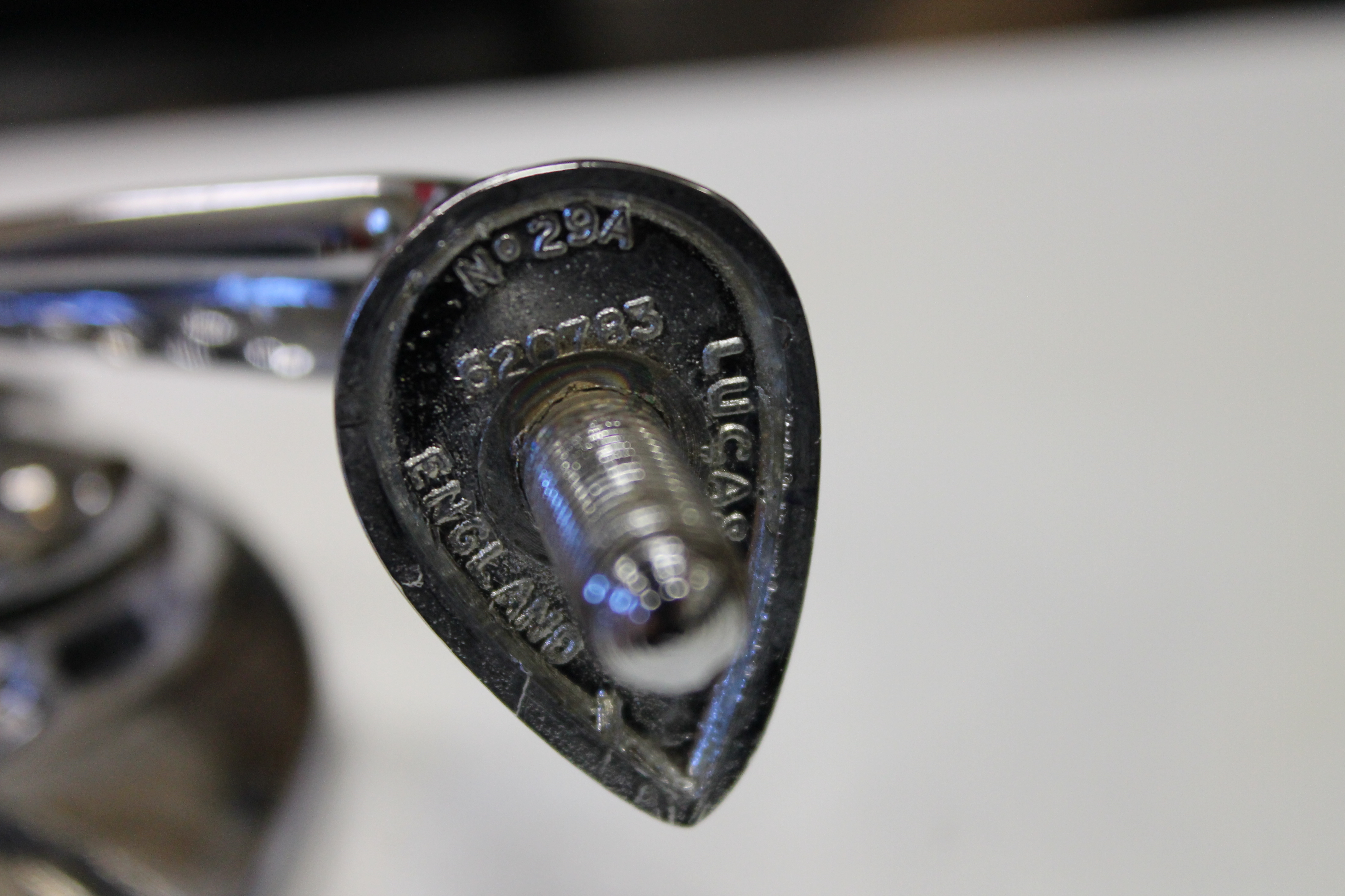
The RH(D) mirror Lucas part number 580733 is known as Lucas model 406/29: this a chromium plated 4¼” round exterior mirror with mounting Bracket 620783. Similarly, LH(D) mirror Lucas part number 580736 is Lucas model 406/41 and is fully identical apart from the Bracket, now part number 620784: the two brackets are “handed”. Note that the indication /29 and /41 relate to the type of Bracket used; this number is also found on the base of the brackets.
The Jaguar XK120 didn’t have the (factory) option to order exterior (wing) mirrors, but there are sufficient photos around to proof that the Lucas 406 mirror was used on the XK120. The most famous is possibly NUB120 which had the first generation Lucas 406/29 and 406/41 from 1950 onwards.
 NUB 120 with early Lucas 406 mirror

Please note that on NUB 120:
- The mirrors have been switched: the RH mirror is now on the LH side, possibly in an attempt to keep the mirrors within the maximum width of the car.
- The mirrors have been placed much closer to the driver and not on the top of the wing above the front wheels as later XKs normally have.
“Second generation” Lucas 406
Early 1953 Lucas introduced an improved version of the 406 series, which was indicated by adding suffixes to the Model number and by a new part number:
- Model 406/29 became 406/1/29A with new Lucas part number 062587.
- Model 406/41 became 406/1/41A with new Lucas part number 062590.
Note that the mounting Bracket (or stem) did not change with the new version and remained 620783 for RH and 620784 for LH.
As mentioned before all 406 mirrors originally had convex mirror glass, meaning the viewing angle was larger but the reflected image itself smaller. Later a flat glass version was added to the range.
The Lucas “Advance Information” catalogue for 1955 jaguar Cars (issued February 1955) mentiones these newer 406 mirrors (Lucas 062587 and 062590) for the Jaguar Mk VII, but “Export only”. The corresponding Jaguar part number is C9091 (with a rubber pad C9904 for the fitting). As stated, initially only as an option for (export) Mk VIIs but later as standard fitment for the Jaguar Mk VIIM.
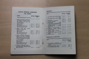 “Salesman’s Data Book” XK 140 listing wing mirrors
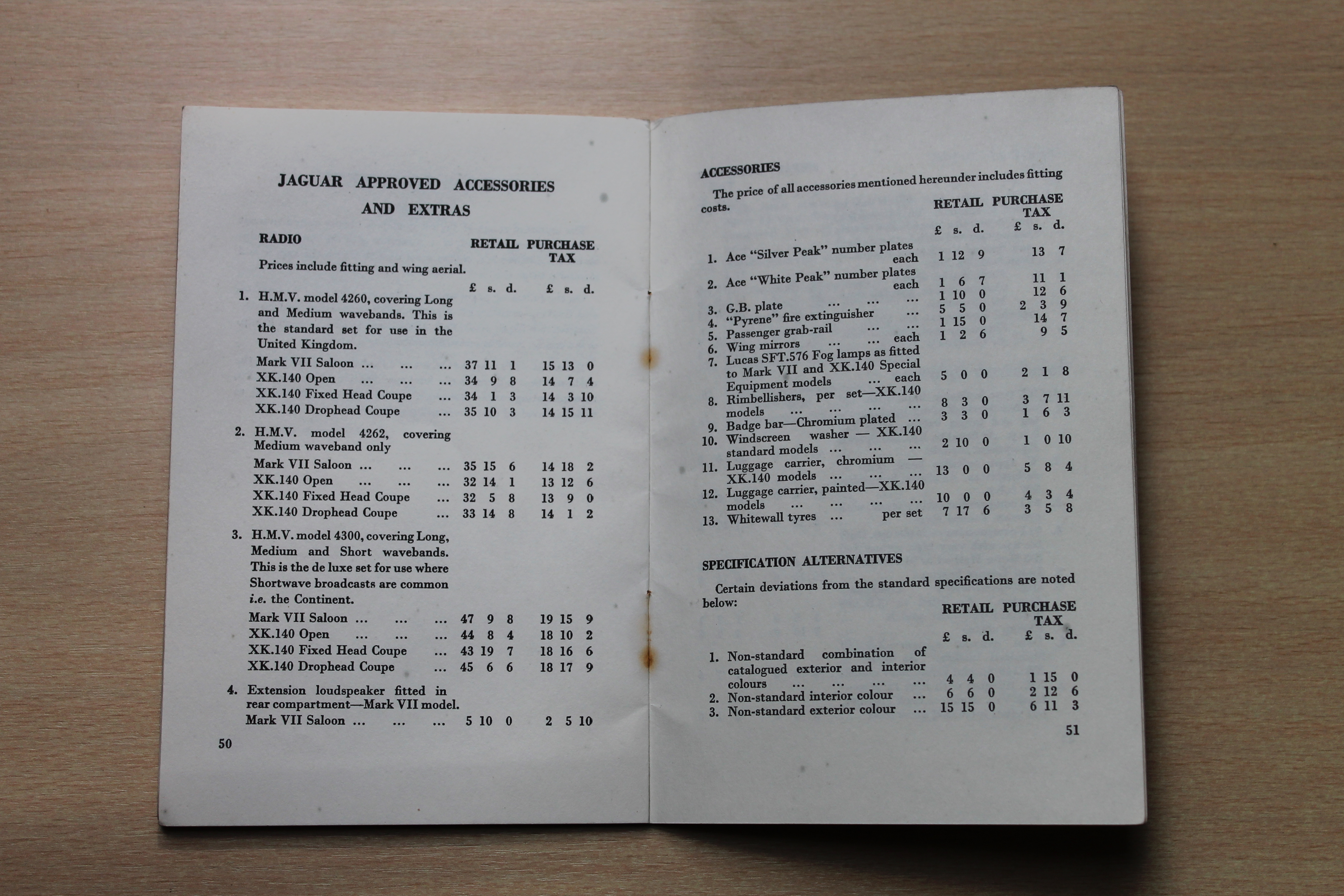
According the Spare Parts Catalogue the XK140 still didn’t have the (factory) option to order exterior (wing) mirrors. But the 1955 “Salesman’s Data Book” for the XK140 (and Mark VII M) clearly states that wing mirrors were available as “Jaguar Approved Accessories and Extras”. Also some photos from the mid 50s show XKs with either a single (driver side) or double wing mirrors. Dealers may have also ordered spare Mk VII wing mirrors (C9091) and holes were drilled to mount them.
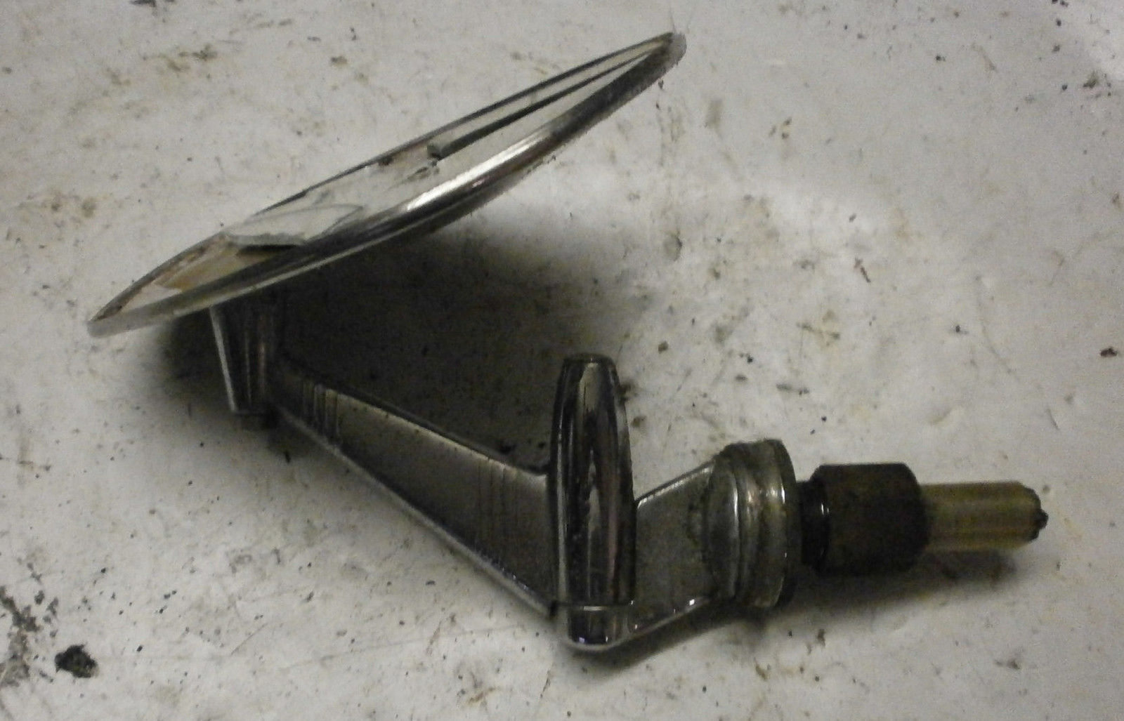
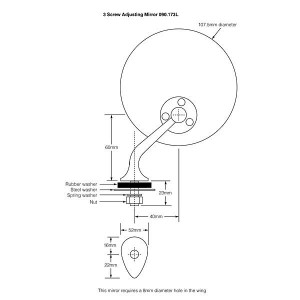 Lucas 406 mirror dimensions

Technical details of the Lucas 406 range (second generation 1953 onwards)
- Lucas wing mirror RH Model 406/1/29A Part number 062587
- Lucas wing mirror LH Model 406/1/41A Part number 062590
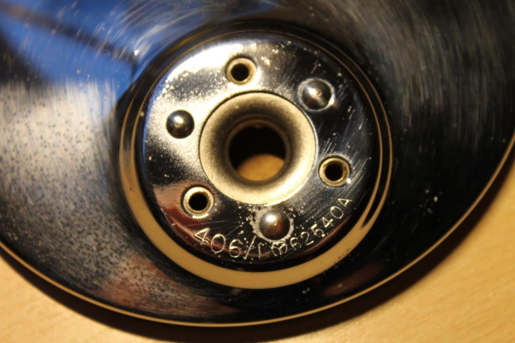
- Mirror head 406/1 Part number 62540A stamped on mounting flange
 Original 406/1 65240A three screw mirror head
- Screw, ball clamping fixing Part number 655453 (3 pcs) RCSK slotted chromed 4BA x ½”
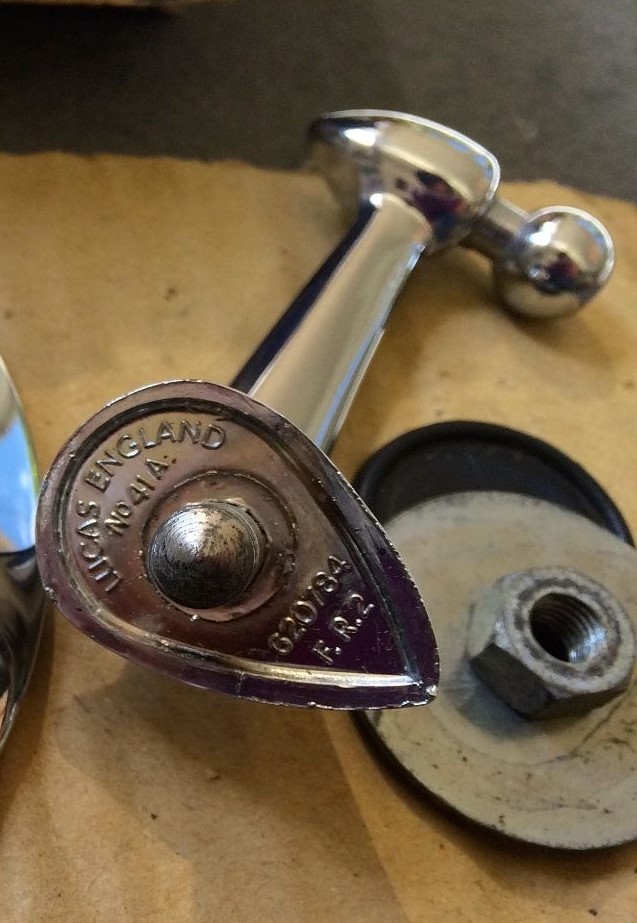
- Ball clamp (stamped “Lucas Made in England”) Part number 620786
 Original ball clamp

- Bracket assembly RH Part number 621740
- Bracket assembly LH Part number 621749
- Nut (BSF5/16 x 22), brass cadmium plated, fixing mirror to wing Part number 182519
- Washer shake proof for Nut 182519 Part number 188471
- Washer, plain, OD 1½ “, under wing Part number 580735
- Pad, rubber, base Part number 580734
 Text on original rubber pad: LEW 16

- Bracket RH Part number 620783
- Bracket LH Part number 620784
 Note the Bracket models numbers 29A and 41A next to the part numbers casted in the base.
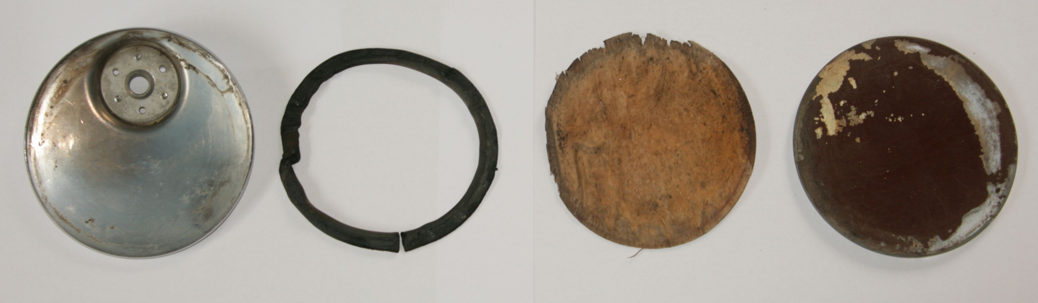
The mirror glass is held in the chromed mirror head by folding the outer rim over the glass (in a rotational process). The glass is sealed by a rubber ring and backed by thick paper. See photo.
 Photo Tadeusz Malkiewicz
Addition of flat glass mirrors: the Lucas 407 range
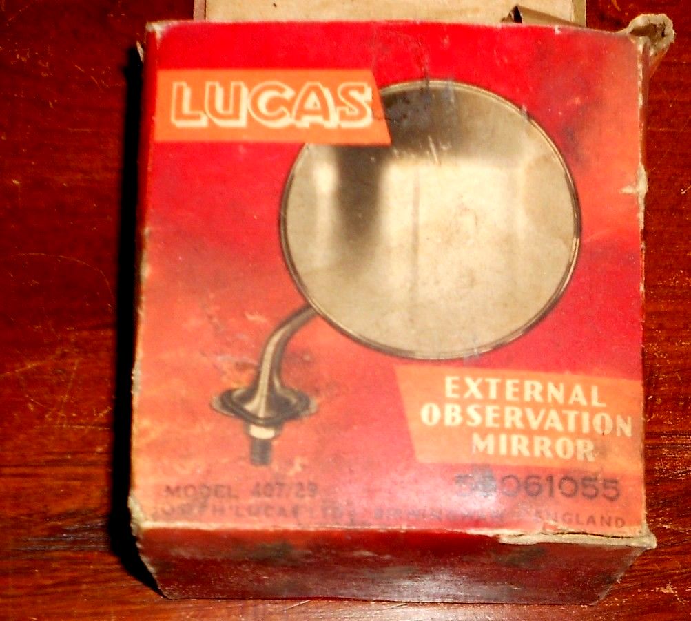
Late 1959 or early 1960 a flat glass range was added next to the model 406. The new versions were 407/29 (for RH) and 407/41 for LH mirrors. Also note that the Lucas part number was no longer stamped on the mirror head. A complete survey of 1967 Lucas catalogue numbers under the chapter “Recommended Accessories”:
- Model number 406/29 (RH) convex glass: 59061047
- Model number 406/41 (LH) convex glass: 59061049
- Model number 407/29 (RH) flat glass: 59061055
- Model number 407/41 (LH) flat glass: 59061056
- Model number 407 (LH=RH) flat glass 59061057 (see next paragraph)

 New box for 407/29 (59061055) flat glass mirror Lucas 407/41 (59061056) flat glass mirror

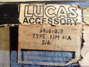 Lucas 59061047 LH Convex mirror Lucas 407/41A but other code 54061029

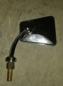
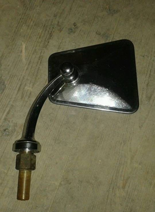
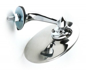
- “Third generation” Lucas 407/112; symmetrical two screw mounting
This version was introduced late 1959 or early 1960. It is based on the (new) flat glass 407 mirror head but received a new bracket (Lucas 112) that could be used both left and right . This model was about 15% cheaper than the 406 or 40729 and 407/41 models, that remained however in the programme. Some Jaguar XK150s and some E-types have been seen with these mirrors from new, but it is unclear whether this is a factory (optional extra) mounted version or a later addition.
 Lucas 407/112

The change implied a new type of Bracket (Lucas 112) which was now mounted on wing, pillar or door using 2 self-tapping screws instead of the single larger (5/16”) bolt of the previous two generations. This change necessitated a different base to create sufficient space for the two screws. This mirror is indicated as Model 407/112 and the part number for the complete mirror is 59061057 (dated 1967). The Bracket Lucas 112 has part number 521545 and “BS 1004A” casted in the base (the latter being the early British Standard for “Specification for zinc alloys for die casting”). Model 407/112 was never offered with a convex mirror head, also because now the mirror could be mounted closer to the driver. The way the mirror had to be adjusted remained the same.

 Later model 407/112 flat glass mirror with symmetrical base and 2 screw mount; Lucas 59061057
The C.9091 (the “second generation” 406, made by Lucas) was most likely initially continued when the XK150 was introduced in 1957. For the first time the wing mirror was included in the Spare Parts Catalogue as an “optional extra” that could be ordered from the factory. The XK 150 Spare Parts Catalogue mentiones part number C.16114 for the wing mirrors; this may refer to the modified Lucas model 407/112 with Lucas part number 59061057 (see above) as supplied from 1959/1960.
This (third generation) Lucas mirror type is also seen on (Series 1) E Types, although TEX mirror types may have been used as well around that time.
Other Lucas wing mirrors
Characteristically the Lucas 406/407 type of mirrors all used a 3 screw clamp for mounting the mirror head to the bracket/stem. As we have seen above, different brackets have been added to the programme (see also example “third generation”) but we have seen more bracket versions: see unknown example below. Model number unknown.
 Unknown Lucas model number
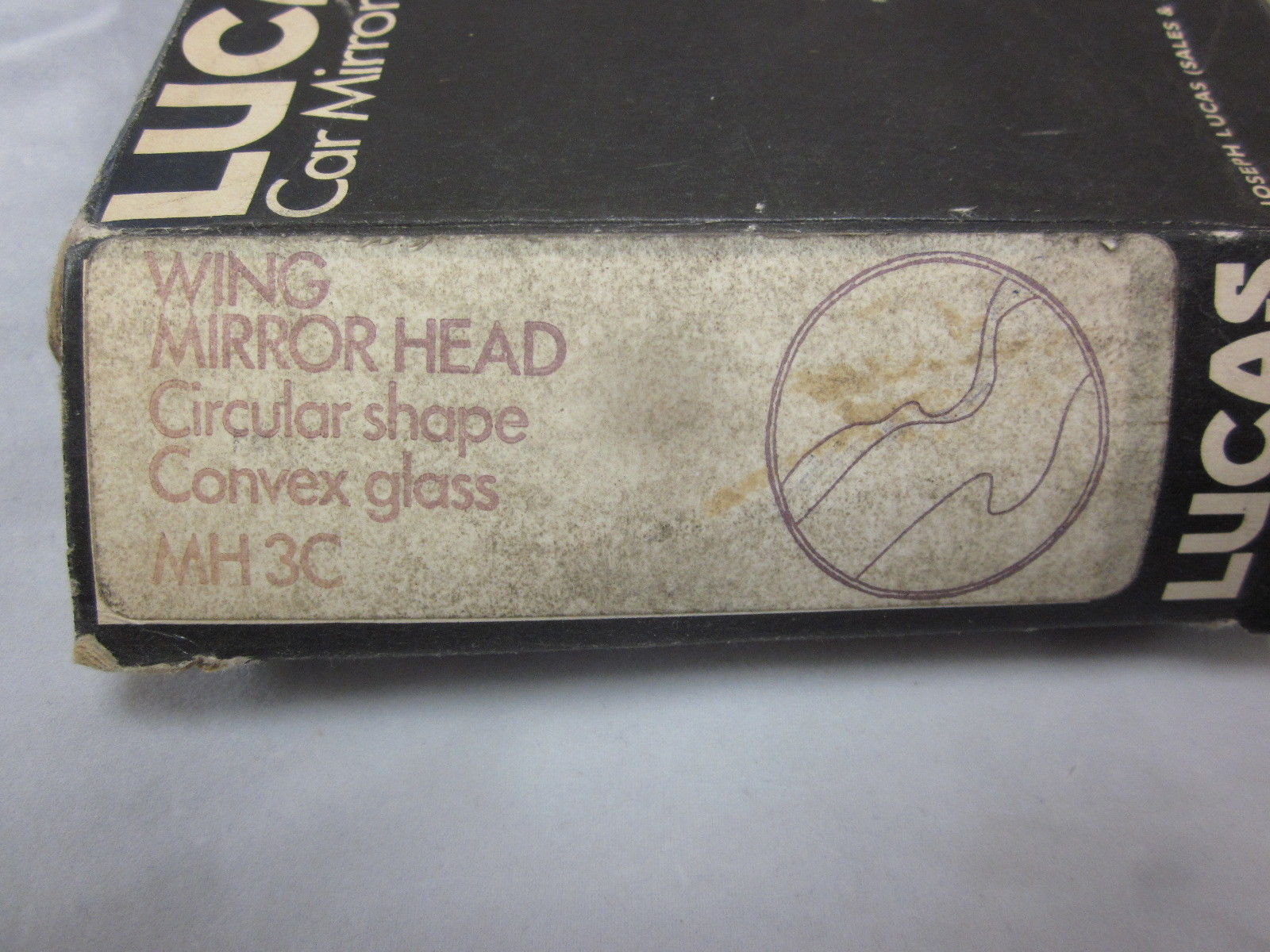
Years later (1970s) Lucas switched over to a new mirror head fixation (MH 3) with a single bolt permanently attached to the mirror head. These mirror heads are no longer interchangeable with the 406 kind of mirror heads. This fixation system is more or less identical to e.g. the TEX system. The convex mirror head was coded MH 3C and we may assume that the flat mirror was coded MH 3F (unconfirmed).
As we will see later, Magnatex had meanwhile introduced the so-called “spring back” system whereby the complete mirror was mounted on a spring mechanism allowing the assembly to flex in case someone/something hits the mirror. Lucas’ answer was to use special mounts to be placed between the existing mirror base and the wing (fender). These wing mirror “spring back” type of mounts had part number Lucas 062624. These mounts included a spring mechanism encased in rubber. The screw on the photo is only for packaging/transportation purposes.
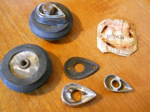 Special Lucas kit 062624 for “Spring back” upgrade

Change-over from Lucas to TEX (Magnatex)
(Magnatex Limited in 1962: Bath Road, Harlington, Hayes, Middlesex, UK.)
In the early 1960s a (gradual?) change-over took place whereby Lucas mirrors were replaced by mirrors manufactured by Magnatex under the brand name TEX. Lucas catalogue CCE 906/62 of April 1962 “Quality Equipment and Spare Parts 1962 – Jaguar” only lists an Interior Mirror (Lucas 680) and no exterior mirrors any more. However, we do know that the supply of Lucas model 406 and 407 exterior mirrors continued until the early 1970s.
This is a rather difficult period to establish which mirror version was used on what model. In the early 60s we see mirrors on the XK 150 (and the Mk VIII as well) that sometimes are Lucas while others are TEX. Of course this could also be a mix of “factory optional extras” and dealer mounted mirrors, but the information available does not provide a clear timing for the change-overs. Some input for discussion:
According the Spare Parts Catalogue the Jaguar XK 150 (and the Mk VIII) received a revised wing mirror with Jaguar part no. C16114 for both sides in the early 60s. After the introduction of the E-Type in 1961 this mirror was also an “optional extra” on this car. This mirror, manufactured by Magnatex (TEX), had a spring loaded base, curved arm, round head and a flat mirror glass. It was no longer handed but fits the LH or RH side because the mirror head can be installed from two sides. There are apparently two versions of this wing mirror: Jaguar C16114 and Jaguar C16114/1 which have the same stem (bracket) but the first has a round mirror head while the latter has a (tapered) rectangular shaped mirror head. Most Jaguar part suppliers of today provide these mirror types as part number C16114 (or C16114/1).
 Jaguar C16114/1 with “continental” mirror head
The Jaguar Mk IX (1959 – 1961) also had two C16114 Wing Mirrors available as “Optional Extras”. They were mounted on a line 1″ outside a straight line from the (red plastic) indicator in the sidelamp casing, and vertically, on a straight line up from the centers of the wheel hubs.
The use of Jaguar C16114/1, however, may have been short lived as becomes clear from Jaguar’s proposed solution in Bulletin A.13 dated December 1961. This bulletin describes a TEX “Viewmaster” adjustable mirror bracket of the “Spring Back” type with “Continental” type mirror head : this “Continental” mirror head type is (tapered) rectangular and no longer round. Also note that the mirror is placed on the bonnet (hood) of the E-Type. This TEX mirror apparently received Jaguar part number C19909. These mirrorrs were supplied with the car but not installed because of transport problems.
 C19909 from 1968
So it looks like wing mirror C16114 was replaced soon after its introduction by Jaguar part number C 19909 which is defined as Magnatex M2VC/6C. This C19909 wing (fender) mirror was fitted to cars exported to countries where external mirrors were compulsory like Belgium, Denmark, France, Germany, Holland, Luxembourg or Switzerland. It was also supplied to special order.
The same TEX system could also be supplied with a round mirror head, as can be seen on the photo below. This type of adjustable bracket has been used on Jaguars from the early till the mid 60s (e.g Jaguar S-type).
 TEX adjustable bracket with round mirror head

Later Jaguar Mk10 and 420G cars had wing mirrors Jaguar part number C20819 with additional description MC120/6C which we assume is also made by TEX. This (most likely) is the last wing mirror used by Jaguar after which only door mounted mirrors were used as exterior mirrors. Jaguar Service bulletin A 15 dated July 1962 shows the correct position 14 1/2 inches back from the edge of the outboard lamp. It also shows a drawing of the correct mirror C20819.
For the year 1968 all LHD E-Types got a new LH door mounted mirror Jaguar C.28517 which is also described as SA365 (which might be a TEX number). The matching RH door mirror has Jaguar code C30827. This mirror is also known as the “Swan Neck” and can also be (or has been) used as a wing mirror. This mirror is mounted using two self-tapping screws and a hole (special shape) that allows the use of two speednuts in the door skin or wing. This mirror is still available.
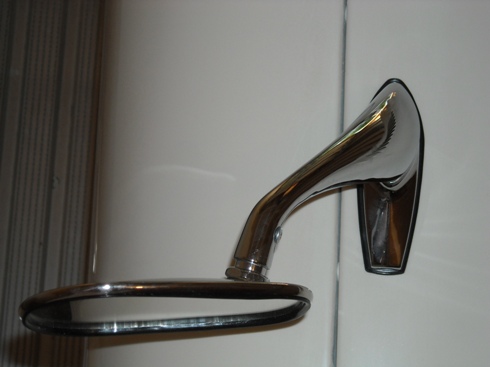
Door mounted Jaguar C28517 “Swan Neck” mirror. Also wing mounted on e.g. later E-Type (Right)
Modern replacements
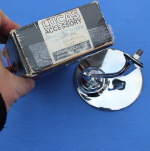
The “Lucas type” wing mirror is newly available from most parts suppliers, but in many cases these are not entirely identical to the original version (either generation 1 or 2):
- The Clamp part number 620786 is often not stamped “Lucas Made in England”.
- The casted (part) numbers at the underside of the Brackets have been deleted.
- The 3 screws for the clamp should be of the “raised countersunk” type with a slot, whereas the modern versions have “pan head” crosshead screws.
 Modern replica “Lucas style”

However, based on the data provided in this survey, it should be possible to find a contemporary (derived) version that still has the required correct parts.
For the more specific types (example “third generation”) it will be much more difficult, but they are offered from time to time on e.g. Ebay.
TEX mirrors are still manufactured today, although not always completely identical to the specific version you might be looking for.
Jaguar XK140 mud shield extensions
Introduction
The front mud shields (left and right) prevent the ingress of water and dirt into the space behind the front side wings. It is evident that water and dirt will cause corrosion where in particular the bulkhead side structures are prone to rusting and repairing is a very labour (and thus cost!) intensive affair. For reference purpose, the front mud shields (or Diaphragm Assembly as Jaguar calls them) are identical for the OTS and the DHC but the FHC has different versions:
- OTS/DHC part numbers BD8401 and BD8402
- FHC part numbers BD10079 and BD10080

 Mud shield for XK 140 FHC
Where the mud shield stops at the bottom remains an opening between the lower part of the side wing and the extended door sill. Through this opening water and dirt can (over time) endanger the structural strength of the door hinges but also enter the cabin and more in particular the rear side of the trim panels left and right beneath the dashboard. This will certainly not contribute to the life of these plywood or Millboard panels, which is so often observed during a restoration. It is unclear why Jaguar left these openings exposed and opted to only partly cure the issue with the actual mud shield design, whereby so much attention was spent sealing the sides of the shield with a special rubber profile but nothing at the underside.
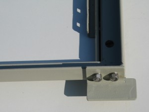
Mud shield extensions
It is possible to close the opening between side wing and door sill with a simple bracket made of sheet metal. The bracket rests at one side on the lower edge of the side wing and is fixed with (e.g. 3 bolts M6 or UNF ¼”) to the horizontal flange of the sill (extension). The forward end of the bracket is bended under an angle parallel to the mud shield and positioned under that shield. Material can be aluminium, zinc plated steel or even stainless steel of a suitable gauge. The example is made of 1.2 mm zinc plated steel that will be powder coated in black for extra protection.
Please note that( probably all) Jaguar XK bodies have some difference in their dimensions, so the drawing below should be used as a guide. Every given dimension should be checked against those of a particular XK body. The drawing is for the LH side of the car; the RH side is simply mirror image. The photo below gives an impression of the RH side bracket.


Once installed the bracket looks like this (see photo below). A small (draining) gap is left between the bracket and the beginning of the door bottom.
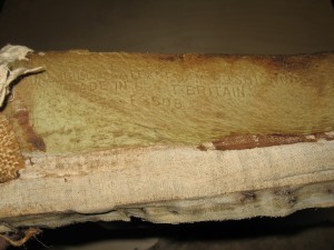
Felt for Fuel tank XK 140
Felt used for fuel tank XK 140
Felt is used between the fuel tank and the chassis & body, but the actual amount, size and position of the various pieces of felt remain unclear from the information in the Service Parts List. Listed are the following items for the XK 140:

The (black) felt used by Jaguar is about ⅛” (or 3 mm) thick and normally 2”(or 50 mm) wide (except C8414 which is 1”or 25 mm wide). The positions of the above pieces of felt:
- Basically the XK 140 fuel tank has 3 felt strips (18” or 45 cm long) placed across the top of the tank front to rear, but the filler opening at the LH side “interferes” with one of these three strips (see 3rd bullet).
- At the LH and RH end of the tank the felt runs from the tank mounting points front to rear over the tank. The RH strip is coded C8373. For the LH strip see 3rd bullet.
- Because the fuel filler opening is placed at the LH side of the tank, the felt strip at this side is not 18” long but had to be cut in two pieces: C8371 and C 8372 with a total length of 16” leaving 2” space for the filler opening.
- The third strip (again C8373) is placed in the centre of the tank parallel to the other strips.
The (original situation) picture below shows where the LH strips went. Black glue was used to hold the strips on to the tank.
 Original
 ![clip_image002[4]](https://www.bobine.nl/jaguar/wp-content/uploads/2013/08/clip_image0024_thumb.jpg "clip_image002[4]") Restored
Restored

![clip_image002[4]](https://www.bobine.nl/jaguar/wp-content/uploads/2013/08/clip_image0024.jpg "clip_image002[4]")
![clip_image002[6]](https://www.bobine.nl/jaguar/wp-content/uploads/2013/08/clip_image0026_thumb.jpg "clip_image002[6]") The top strips installed on the fuel tank.
The top strips installed on the fuel tank.
![clip_image002[6]](https://www.bobine.nl/jaguar/wp-content/uploads/2013/08/clip_image0026.jpg "clip_image002[6]")
There is another 44” (or 110 cm) long and only 1”(or 25 mm) wide felt strip placed along the top of the tank from side to side. This strip is positioned along the front of the top of the tank to protect the tank from rubbing on the chassis cross-member.
![clip_image002[8]](https://www.bobine.nl/jaguar/wp-content/uploads/2013/08/clip_image0028_thumb.jpg "clip_image002[8]") Tank in final position including felt strips
Tank in final position including felt strips
![clip_image002[8]](https://www.bobine.nl/jaguar/wp-content/uploads/2013/08/clip_image0028.jpg "clip_image002[8]")
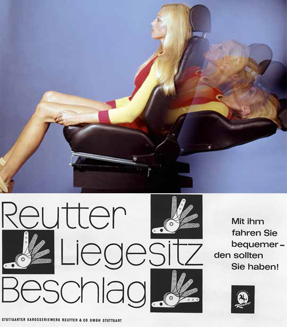
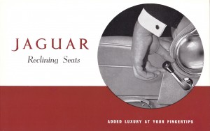
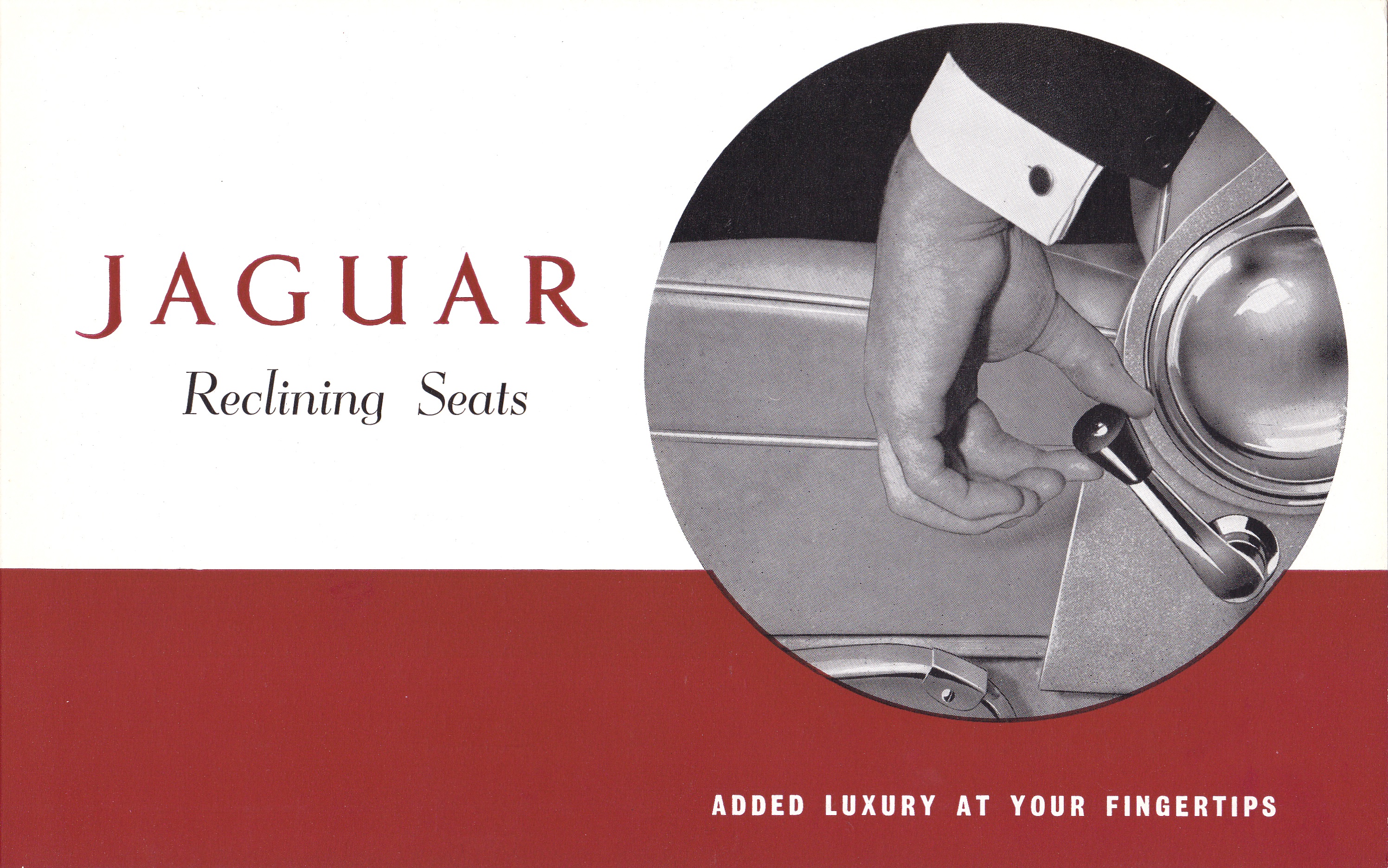
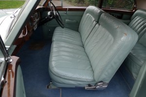
Reutter Reclining Seats for Jaguar
Reutter Reclining Seats as factory option for Jaguars.
The standard seat configuration of Jaguars from the Fifties results in a driving position which is far from ideal. In the early fifties. Jaguar understood that something had to be done, but no solution was available in-house. As far as we know, none of their British suppliers, nor competitors had a reclining solution at that moment.
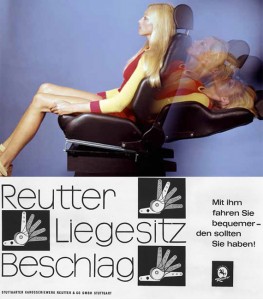 Early 1960’s Reutter brochure
There was one company that had been working on reclining seats after WW2 and had started production in early 1953. Reutter Karosserien of Stuttgart was a German company with a long history: established in 1874 by Wilhelm Reutter with his brother Albert joining the company in 1910. The company built special car bodies for many German brands like Adler, Benz, BMW (incl. Dixi) , Daimler-Benz, Horch, Maybach, NSU, Opel, but also for non-German manufacturers like Ansaldo, Austro-Daimler, Bugatti, Buick, Cadillac, Chrysler, Fiat, La Salle.
The Reutter Reclining kit (German: „Liegesitzbeschlag“) was introduced at the 1954 Geneva Automobile Salon.
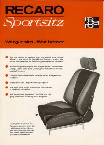 Later 1960’s Recaro brochure; note similar reclining system
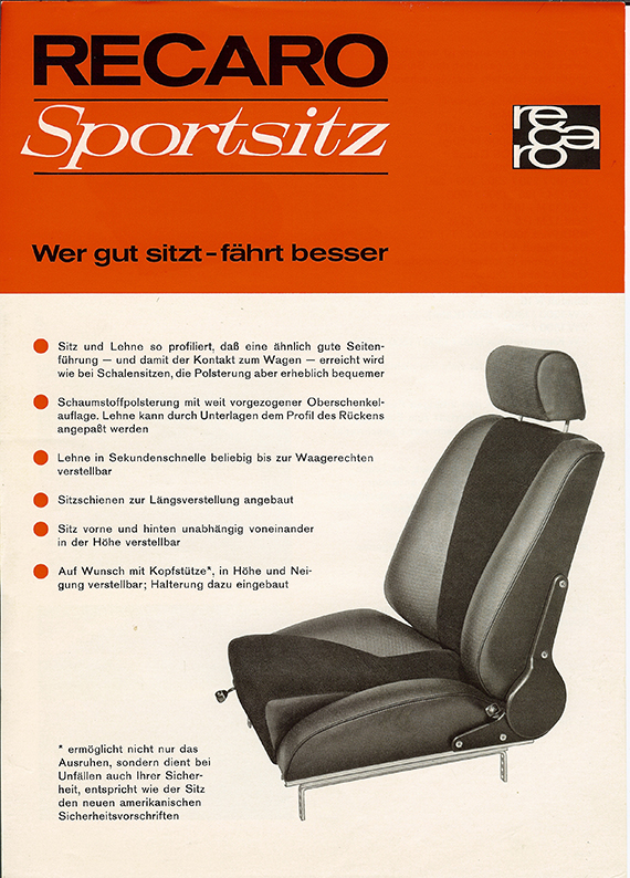
The Reutter subsidiary “Recaro AG“ (derived from Reutter Carosserien) had been established on September 9th 1957 in Glarus (Switzerland). Reutter manufactured the bodies for the early Porsche 356. After the sale of the body works in Zuffenhausen to Porsche in 1963, the “Recaro AG“ company kept their headquarter of the “Recaro GmbH & Co.“ in the former Stuttgart body works. Next to complete seats also seat rails, reclining kits and head supports have been manufactured here. The RECARO Sports Seat was created in this period, which became a worldwide quality benchmark.
Other German manufacturers of reclining systems
Reutter wasn’t the only company manufacturing reclining systems in the early Fifties. The Hüls company (also named Hülsmetall) of Kamen (Ruhr area) made aftermarket systems for the Volkswagen Beetle and Bus that could be bought as an accessory; these systems were mostly manufactured in painted steel and didn’t give that “high-end” impression.
Another company was Keiper of Kaiserslautern (near Frankfurt) that had an almost identical solution as Reutter had, however with a large turning knob instead of the handle for adjusting the seat back. These chromed products were often used for the conversion of Mercedes seats (type 170V and W110). We have to mention here that keeper eventually took over the Reutter company in 1983, but more recently Keiper in turn was sold to Johnson Controls (USA) in 2010.
 Keiper recliner on Mercedes 170 Brochure Mercedes 170 with Keiper system

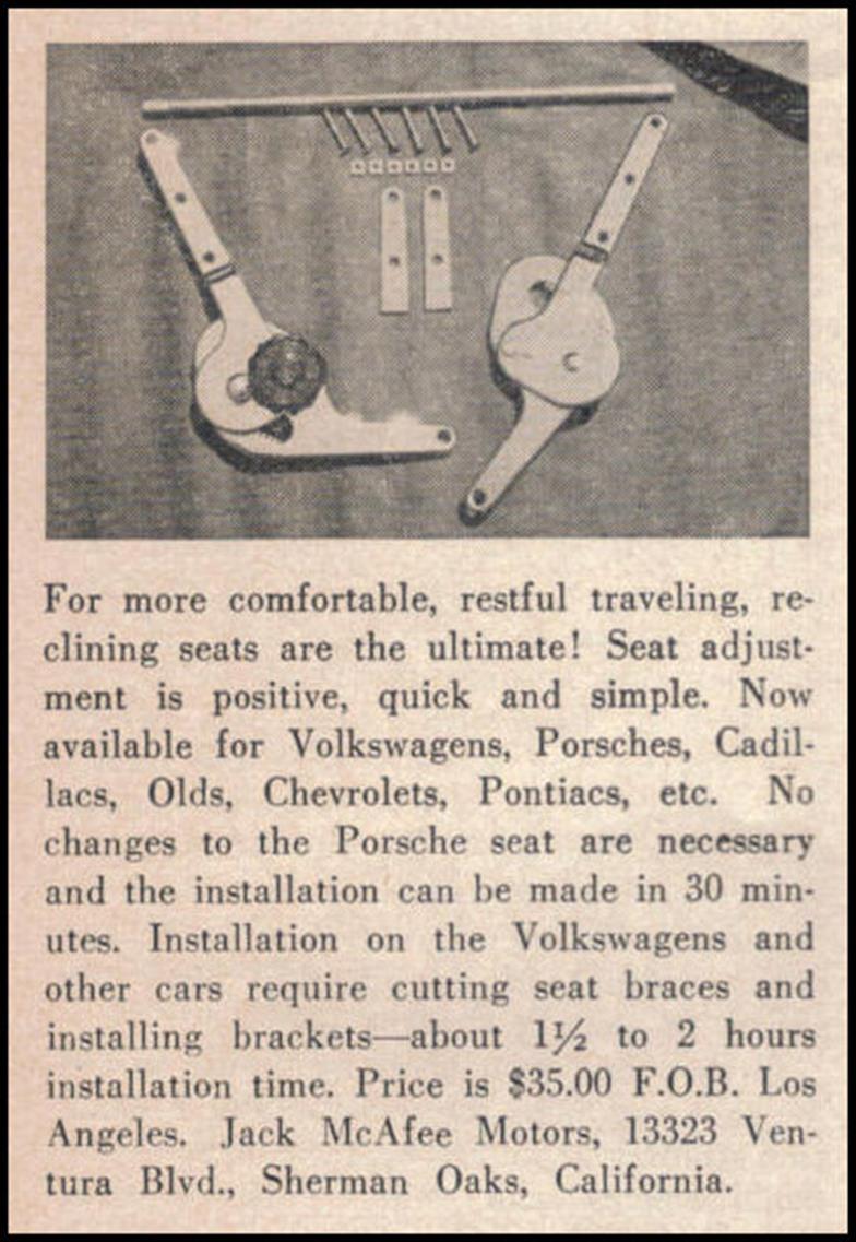
It is interesting to note that the Keiper system was available in the USA from 1954 onwards, long before Jaguar started with the supply of the Reutter option. Jack McAfee Motors of Sherman Oaks, California offered them for $35 for a complete set.
 1954 adverstisement: Jack McAfee Motors importing Keiper systems
Reutter reclining mechanism
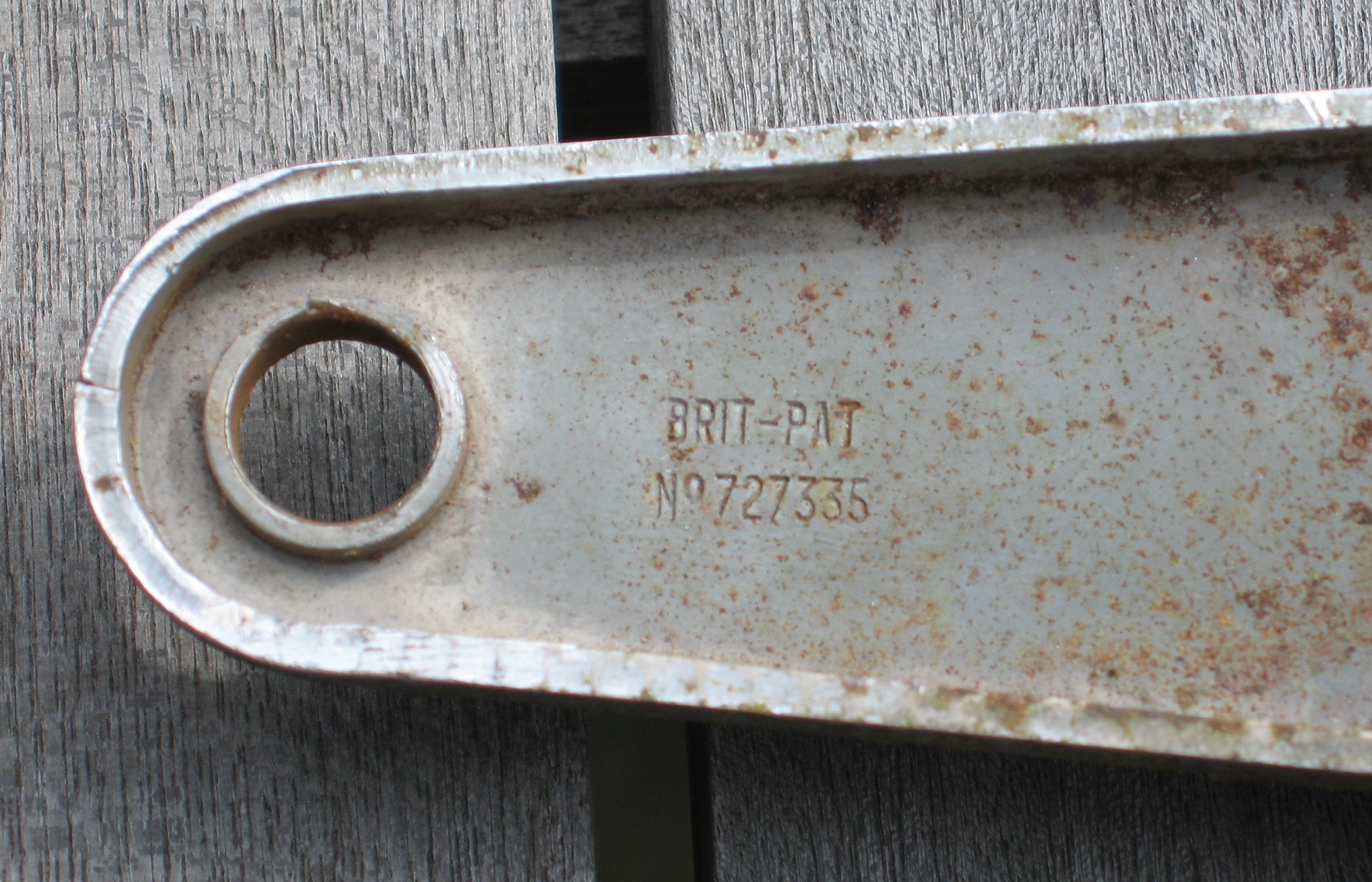
Reutter obtained a German patent (Nr. 881099) on the 29th of June 1953 for a „hinge mechanism for upholstered seats with adjustable back-rest“. Note that Reutter also obtained a British Patent probably to protect their (future?) interest in the UK.
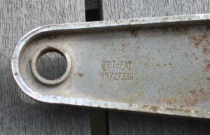 German Patent Nº881099 British Patent Nº727335

Jaguar Reclining Seats by Reutter
After having contacted Reutter in Germany, Jaguar started the development of reclining seats based on the Reutter kits. The supply of Reuter reclining seats as a factory option (factory modified seats using the Reutter kits) started in 1958. In October that year for the first time on a Jaguar, separate reclining front seats became available for the Jaguar Mk VIII and Mk IX (having more or less the same seat). The factory option included both front seats to be executed with the Reutter reclining mechanism. Later it was also available for the Mark 2 and for the XK 150 as well. The Reutter option was in Jaguar’s program for about 3 year: from 1958 up to 1961. Note that Jaguar opted for an “older system” that was in production from 1955 onwards.
Mark VIII (1958-1959)
The Jaguar (UK) price list of October 1958 lists the “Reutter Reclining seats (per pair)” for the first time as a “Proprietary Optional Extra” only for the Jaguar Mk VIII and the (then new) Mark IX. Customers had to pay £52 extra for two recliner seats which doesn’t seem to be expensive if related to an amount of £1800 to £2150 for a complete Jaguar Mk VIII or IX in those days.
 Jaguar (UK) price list October 1958
Mark IX (1958 – 1960)
The introduction of Reutter reclining seats actually coincided with the introduction of the new Jaguar Mark IX. Next to the above reference of October 1958 there is also the US Jaguar Price List from June 2, 1960 issued by the Jaguar Midwest Dist. Inc. of Indianapolis, mentioning the option “Reutter seats” with a Dealer price of $120 and a Retail price of $145.
 Factory photo of Reutter option for Mark IX Original Mark IX Reutter seat
XK 150 (1959 – 1961)
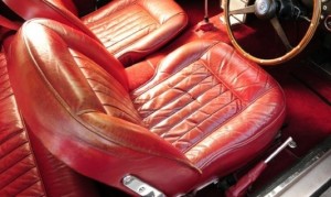
There are some references regarding Reutter seats in an XK 150 although no options-list seems to be available that explicitly mentions the Reutter reclining seat as a factory option. Jaguar XK 150 S 3.8 FHC with chassis number T8251328DN, produced around 18th February 1960, received apparently the Reutter conversion according the H&H auction specification of 2014. Another possible example is the XK 150 S 3.8 FHC with chassis number T825134DN manufactured end of February 1960 (with Reutter seats according Coys auction description of 1993). Photo’s of a third known example are shown below: a 1958 XK150 DHC RHD has 2 Reutter seats that apparently have been modified in a very early phase using new leather kits (with 7 pleats i.s.o. 9) .

 Two Reutter seats in a 1958 XK150 DHC RHD. Note the combined solution for seat cushion & frame.


 Professional factory conversion on XK 150 or poor DIY?
I acquired a Jaguar XK 150 Reutter left hand seat (which later has been modified for application in an XK 140) but there is sincere doubt whether this particular Reutter seat was actually manufactured by Jaguar for the XK 150, as this conversion was far from professional (see photos).
“Reutter” for the Jaguar Mark 2 ?
We noticed that some Jaguar Mark 2 cars for sale refer to have “Reutter seats”. Even Nigel Thorley in his book Original Jaguar MKI/ MKII mentions on page 64 “Reutter Reclining front seats” available as Optional Extra. It is very unlikely, however, that Reutter kits have ever been used for the conversion of early Mark 2 seats .

 Non-Reutter reclining system Brochure introducing “Special Jaguar reclining seats” on Mark 2
We had to conclude that all examples of Mark 2 cars claiming to have “Reutter seats”, did not have a reclining system manufactured by Reutter. So it looks like “Reutter seat” had become a generic name for a Jaguar reclining seat in this era. Jaguar issued a special brochure on reclining seats for the Mark 2 in which it mentioned “Special Jaguar reclining seats”, whereas for the Mark IX cars Jaguar spoke openly about “Reutter reclining seats”. This later Jaguar reclining system was manufactured from March 1963 onwards and is also mentioned in the Jaguar Mark 2 Spare Parts Catalogue. This catalogue also mentions a “Kit of Parts” (Jaguar BD.24397 (LH) and BD.24432 (RH)) for converting a rigid Mark 2 seat into a reclining version. These Jaguar systems can be easily recognized by having a separate chrome handle positioned below the hinge plate (instead of above the hinge plate as per Reutter).
Reutter influence on E-type (XKE) Series 1 (1964 – 1967)
Although none of the E-type (XKE) versions ever had a Reutter system installed, we still mention the Series 1 from 1964 (coinciding with the introduction of the 4.2 litre engine) up to 1967, because the design of this reclining system was clearly inspired by the earlier Reutter version: the shape of the aluminium casting was derived from the Reutter design.
 Reutter inspired design Series 1 E-type Series 2 had a different reclining system

The Series 2 models had a completely redesigned reclining mechanism, no longer supplied by Reutter.
Other period cars with Reutter reclining seats
Most obvious user of Reutter reclining mechanisms was of course Porsche: their 356 models had them from 1953 onwards (even before the official 1954 introduction in Geneva). Other car manufacturers in the 50’s that used Reutter reclining mechanisms were: Alvis TD21, Aston Martin DB4, Bentley S1, Bristol 406, Volkswagen Beetle and Bus (T2, T5), Volvo (B16 and pre 1965 B18), Mercedes, Borgward, Facel Vega, and probably many others.
 Reutter seats on Aston-Martin Bentley S1 with Reutter seats
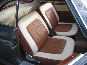
 Borgward Isabella with Reutter option Volkswagen Beetle with Reutter option


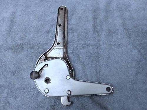
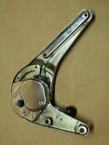
Overview of recliner mechanisms.
 First type reclining system with long arm and three mounting bolts is used by Jaguar
There are two basic types of Reutter reclining mechanisms that look almost identical. The first version had a rather long arm with three mounting bolts connected to the back rests. This version was already in production by 1955 and modified a number of times, differences mostly related to the shape of the aluminium cover over the large spring. The above examples, showing a spring cover attached with 2 screws to the upper arm, often have a date code from 1955 if applied in German cars. The Jaguar versions, however, have the “British Patent” stamped but lack a date code.
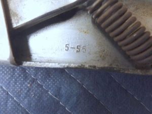
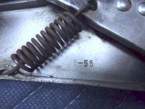 Date code 5-55 and 6-55 on the Reutter type as used by Jaguar (but from an early Porsche 356)


 Beware: this later Porsche 356 C Reutter system doesn’t fit Jaguar seats

Although the Reutter system for the Porsche 356 C (1963-1965) looks identical to the aforementioned version (3 mounting holes and black adjustment knob), the above shown later version cannot be used for the Jaguar seats as the installation and synchronization is completely different.

 Later shorter version with only two bolt holes
From about 1957 onwards we also see versions whereby these arms had been replaced by a shorter version with only two bolt holes. Note that both versions have already been described in the original patent application of 1953. Not used on Jaguar seats!
Jaguar applied the first Reutter generation type from 1958 onwards and kept this model over the entire period of Reutter reclining seats up to 1961. All of these hinges have steel tubes that connect the LH and RH hinges on each seat.
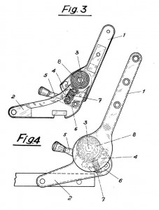
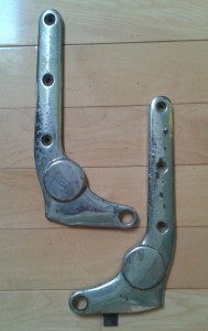
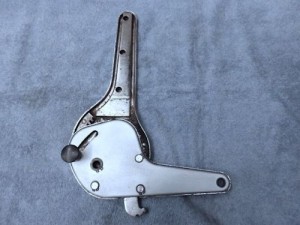
The reclining mechanism
Reutter used chromed aluminium castings rotating around a spring-loaded hinge. These assemblies were placed at both sides of the seat (LH and RH castings). The LH and RH mechanisms were connected by a cross-over tube “synchronising” the seatback movement. A short lever allowed the position of the backrest to be changed relative to the base using a gearwheel mechanism coupled to the cross-over tube. The casting mounted to the backrest was longer than the one connected to the seat base. The castings were fixed with 3 bolts to the seat back and with only 1 (swivelling) bolt to the seat base: this allowed the seatbacks to be hinged forward in order to get to the rear seats.
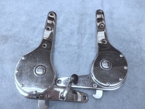
 LH and RH reclining mechanisms

![clip_image002[4]](https://www.bobine.nl/jaguar/wp-content/uploads/2013/06/clip_image0024_thumb1.jpg "clip_image002[4]") Connecting tube “synchronising” the seatback movement
Connecting tube “synchronising” the seatback movement
![clip_image002[4]](https://www.bobine.nl/jaguar/wp-content/uploads/2013/06/clip_image00241.jpg "clip_image002[4]")
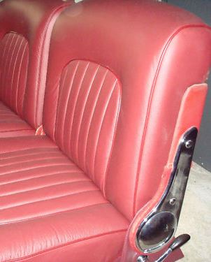
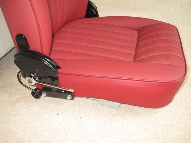
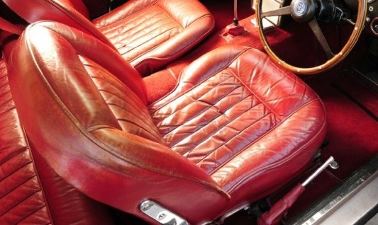
Jaguar XK 140 FHC recliner seat conversion
 Reutter front seat for Jaguar XK 140 FHC

As the introduction of Reutter reclining seats as a factory option started only in 1958, it seemed unlikely that this option was ever used for the XK 140 series. However, there is apparently (at least) one example of an XK 140 with a reclining seat installed by the factory: Jaguar build records show that the (RHD) XK 140 FHC with chassis number 804574 (registration number WNK 843) was manufactured on 20th December 1955. The first owner is registered as Major Robert Cunningham-Reid. Mr Cunningham-Reid has confirmed that the car was modified by the factory with a Reuter reclining seat on the driver’s side.
I obtained an XK 150 seat with Reutter reclining mechanism and converted the original Jaguar XK 140 (FHC) driver seat to a reclining version. It requires a complete dismantling of the seat and some constructional modifications, however none of them are too complicated.
![clip_image002[6]](https://www.bobine.nl/jaguar/wp-content/uploads/2013/06/clip_image0026_thumb.jpg "clip_image002[6]") Base frame XK 150 (left) is wider than XK 140 (right)
Base frame XK 150 (left) is wider than XK 140 (right)
![clip_image002[6]](https://www.bobine.nl/jaguar/wp-content/uploads/2013/06/clip_image0026.jpg "clip_image002[6]")
The distance between the LH and RH reclining assemblies is determined by the frame width of the seat base (see photo). As the base frame of the 150 seat is 35 mm wider than the one of the XK 140 (about 423 mm), the existing Reutter system had to be modified in three ways: (1) the cross-over tube had to be shortened by 35 mm to fit and (2) spacers had to be used for fitting the RH recliner assembly to the metal inner support construction of the seat back and finally (3) a piece of plywood is placed on the outside of the LH side to compensate for the spacers on the other side (see photo).
![clip_image004[6]](https://www.bobine.nl/jaguar/wp-content/uploads/2013/06/clip_image0046_thumb.jpg "clip_image004[6]") Spacers for RH recliner assembly to metal inner support
Spacers for RH recliner assembly to metal inner support
![clip_image004[6]](https://www.bobine.nl/jaguar/wp-content/uploads/2013/06/clip_image0046.jpg "clip_image004[6]")
![clip_image006[7]](https://www.bobine.nl/jaguar/wp-content/uploads/2013/06/clip_image0067_thumb.jpg "clip_image006[7]") Plywood on the outside of the LH side
Plywood on the outside of the LH side
![clip_image006[7]](https://www.bobine.nl/jaguar/wp-content/uploads/2013/06/clip_image0067.jpg "clip_image006[7]")
![clip_image004[4]](https://www.bobine.nl/jaguar/wp-content/uploads/2013/06/clip_image0044_thumb1.jpg "clip_image004[4]") “Synchronizing” tube end with internal square
“Synchronizing” tube end with internal square
![clip_image004[4]](https://www.bobine.nl/jaguar/wp-content/uploads/2013/06/clip_image00441.jpg "clip_image004[4]")
Note that the ends of the cross-over tubes are square on the insides (to fit a gearwheel) and therefore the tube has to be shortened in the middle: use a solid rod to reinforce the middle section before welding the tube.

 “Stop section” replaced by a new bracket


Another modification relates to the stops for the seatback: the original “stop section” on the rear of the base frame has to be cut off and replaced by a new section (see photo).
 Original hinges removed

On the XK 140 seatback frame the original hinges have to be removed as their presence is no longer required (see photo).
 Final result in an XK 140 FHC

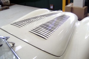
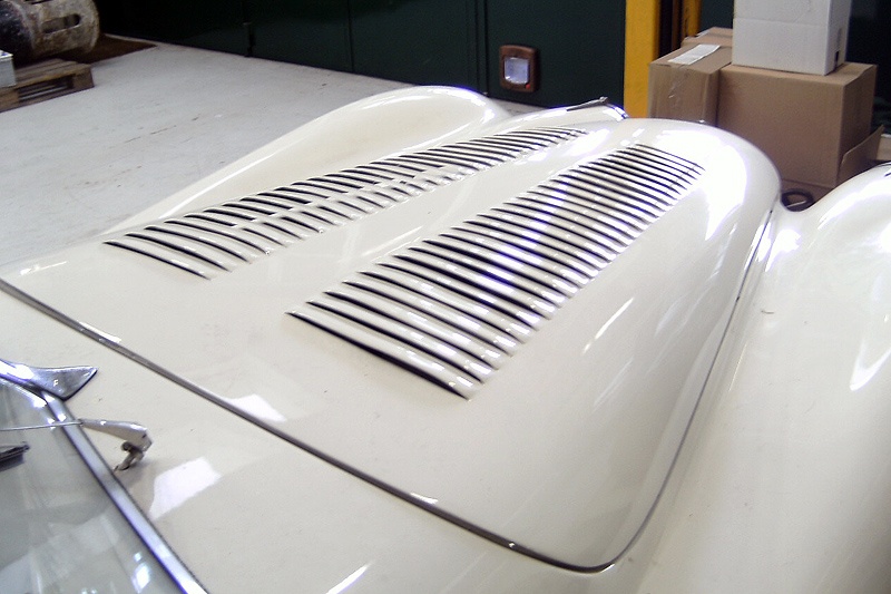
Bonnet louvres for XK 140
Bonnet Louvres for XK 140
Louvres
One of the ways to keep the coolant temperature under control is to increase the amount of air through the radiator. Next to installing an electric cooling fan, bonnet louvres may help (of course under the condition that the car is moving). The latter solution also doesn’t consume any power from the engine. This is the reason why in particular race cars (including Jaguars) had louvres installed in bonnet and/or wings.
Jaguar XK’s
Jaguar used this principle for their XK’s and installed louvres in various versions that took part in active racing. In particular during the early years, C-types and some XK 120’s received this option, but there are also at least two examples of the same operation for the XK 140.
Dimensions
It is rather difficult to obtain exact data on the position, number and size of the louvres in the bonnet of the XK120 and the C-types. Furthermore, we note that the dimension’s differed per type and per year because they were made by hand and the development of the cars continued of course. What becomes clear, however, is that there are always two rows of louvres symmetrically located at both sides of the middle of the bonnet.
(All dimensions given here serve to help getting a better insight, but claim in no way to be exact).
Louvres for XK 120’s
Most prominent example is Clarck Gable’s second XK 120: a 1952 steel-bodied OTS with chassis number 672282. After his complaints regarding the lack of ventilation in the engine compartment Jaguar punched two rows of slots in the bonnet (see below).
 Louvres in Clarck Gable’s 2nd XK 120
Jaguar XK 120 OTS Works Competition car with registration MDU 524, had a different bonnet louvre pattern. This originally May or June 1952 built RHD OTS with chassis number 660986 is well-known after it had been extensively modified in 1953 to become the streamlined car that set a speed record of 173.159mph on the Jabbeke motorway in Belgium. Before and after that event it participated in a more standard execution in many races in the UK driven by Albert Powell and Brian Redman.
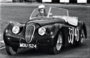
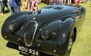 Albert Powell in MDU 524 in 1957 MDU 524 with its 1953 streamlined body in 2014
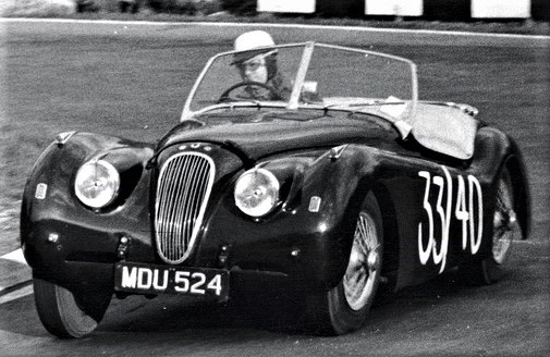
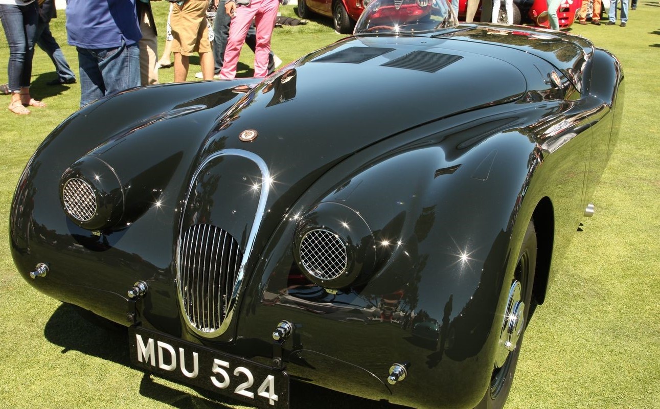
Whereas Clarke Gable’s car had triangular shaped louvres almost over the entire bonnet length, the MDU 524 louvres have an almost square lay-out, much more in line with the later XK 140 patterns (as we will see below).
Louvres for XK140’s
Most prominent example of an XK 140 FHC with bonnet louvres is the 1956 Le Mans car driven by Peter Bolton and Bob Walshaw: registration number PWT 846 and chassis number S 804231 DN. This was a SE version in standard form with apart from the optional 2” H8 carburettors and an additional fuel tank, also got extra air intakes at the front and louvres in the bonnet.

Clausager in his book “XK 140/150 in detail” shows a detailed photo of the louvres which reveals that they have not been made straight in the aluminium bonnet material itself but made in a separate plate and mounted from behind in an opening cut in the bonnet. The louvres are pushed through from the inside and the air opening is in the direction of the windscreen. We count (two times) 16 louvres with an estimated width of 185 to 190 mm (7¼ to 7½”) over a length of about 445 mm (roughly 17½”). This implies that the individual louvres are about 28 mm (1.1”) wide with an opening of about 12 mm (½”). The louvres are placed very close to each other without any space between them (which somewhat reduces the mechanical strength of this section and louvres can be easily bend).

Regarding the exact location of the louvres on the bonnet, the position on the Le Mans car is towards the end of the bonnet close to the windscreen. This was only possible by removing the aluminium reinforcement construction on the inside of the bonnet and welding it back after the louvres have been placed (what may restrict the air flow).
The second example of an XK 140 with bonnet louvres is an early “experimental” OTS (most likely chassis number S 8000033 DN). This car had two additional air intakes at both sides of the grill above the bumper and bonnet louvres, very much in line with the Le Mans car (which was a much later car). It is impossible to reproduce the exact measurements of these louvres, but they seem to be close to the ones of the Le Mans version.

Louvres in C types
Looking at photos of C types we see for the 1953 versions a different pattern for the louvres: two groups of 22 louvres over a total length of about 610 mm (24”) and a width of 210 mm (8¼”), meaning 28 mm per louvre which is identical to the spacing used for the XK 140 (same tooling?).
Making bonnet louvres in an XK 140
When making louvres in an XK 140 bonnet, there are two alternative ways to go:
1. Making two separate plates with louvres and fix those in an opening cut in the bonnet.
2. Making the louvres straight in the bonnet.
When opting for the second method, limitations are created by the reinforcement construction at the inside of the bonnet: the louvres cannot be placed as close to the windscreen as was the case for the Le Mans and Experimental car. And the total available length for the louvres between two reinforcement brackets, allows only for about 10 openings (spaced at a distance, because a certain strength of the bonnet will be appreciated!). The louvres are cut and formed with a special tool and machine (see photos) and the result is very satisfying.
![clip_image002[4]](https://www.bobine.nl/jaguar/wp-content/uploads/2013/06/clip_image0024_thumb.jpg "clip_image002[4]") Making the louvres with a special tooling
Making the louvres with a special tooling
![clip_image002[4]](https://www.bobine.nl/jaguar/wp-content/uploads/2013/06/clip_image0024.jpg "clip_image002[4]")
![clip_image004[4]](https://www.bobine.nl/jaguar/wp-content/uploads/2013/06/clip_image0044_thumb.jpg "clip_image004[4]") Final result (before painting)
Final result (before painting)
![clip_image004[4]](https://www.bobine.nl/jaguar/wp-content/uploads/2013/06/clip_image0044.jpg "clip_image004[4]")
Interior lights XK 140 FHC (BD5367 & 68)
Interior lights XK 140 FHC (BD5367 & BD5368)
The Jaguar parts list shows the following components:

The metal Lamp Housing is referred to as Recess Assembly for the XK 120 or Pocket Assembly for the XK 140 coded BD 5334 and BD5335. Also coded as BF1088/L and BF1088/R


These items are used in the following cars:
- XK120 FHC
- XK140 FHC
- MK1
- MK7/8/9
Please note that the bottom rim of the metal Lamp Housing of the saloon models is sometimes wider than the one of the XK models, but these can be cut to size easily.
Interior Lamp FHC BD5367 (LH) & BD5368 (RH)
The complete assembly of the interior light consists of the following parts:

Early Interior lights had a single ½” large hole for the NEG lamp contact, whereas the POS (Earth) lamp contact had a smaller hole (3/16”) and this contact was connected to the metal reflector. Later Interior lights had two ½” large holes for both lamp contacts, meaning both POS and NEG earth systems could be used.
 Early and later type Reflector.
Assembly comprising Casing, Pocket and Interior Lamp

Spare wheel lid mounting screws
Spare wheel lid mounting screws NS 519/3D
The hinges (BD9374) are mounted to the spare wheel lid (BD9372 or BD11262) with (3 x 3=) 9 countersunk set screws and fit in “T” nuts (BD9909/1) placed in the plywood.
 Hinges are fixed to these “T” nuts with ANF 3/16 thread
Official Jaguar code for the mounting screws is NS519/3D meaning ANF 3/16 x 3/8” CSK slotted set screw. However, since about 1950 the 3/16″ UNF thread doesn’t exist any longer. There are 3 possible alternatives:
- The best equivalent is CSK Slotted No.10 x 32 threads per inch. Diameter for UNF 3/16″ is 0.1875″ and for No.10 is 0.190″. They are however interchangeable and have both the same 55° thread angle.
- British Standard Fine (BSF) has a 3/16″ x 32 thread as well. Normally UNF and BSF have different “thread per inch” but in this case they are identical.
- Also 2BA screws might fit if the thread hole is undamaged: it is about 0.1 mm smaller in diameter and (as the thread angle is only 47.5°) it will fit the UNF thread. The pitch is slightly longer (about 0.02 mm!) than the UNF version.
|
Thread |
Diameter (inch) |
Diameter (mm) |
Pitch (TPI ) |
Pitch (mm) |
|
ANF 3/16” |
3/16” |
4,763 |
32 |
0,79 |
|
No 10 |
0,190 |
4,83 |
32 |
0,79 |
|
BSF 3/16” |
0,187 |
4,75 |
32 |
0,79 |
|
2BA |
0,185 |
4,70 |
31,35 |
0,81 |
Additional information on these thread types:
BSF has a Whitworth 55° thread angle, where as BA has a 47.5° thread angle. So these threads are not automatically interchangeable: in general a BA screw might fit a BSF thread hole if the diameter and TPI are close.
BA is taken from the 19th Century Swiss Thury thread. Its formulation was proposed by the British Association in 1884 and adopted in 1903. BA has in principle metric dimensions. No.0 BA is 6.0 mm diameter and subsequent numbers are in 0.9 progression. Multiply a BA diameter by 0.9 and you have the diameter of the next smaller size. BA screws are nowadays seldom seen and virtually exclusive to electrical fittings (e.g. Lucas) and instruments (e.g. Smiths).
Post-war Triplex Manufacturing Date Codes
Introduction
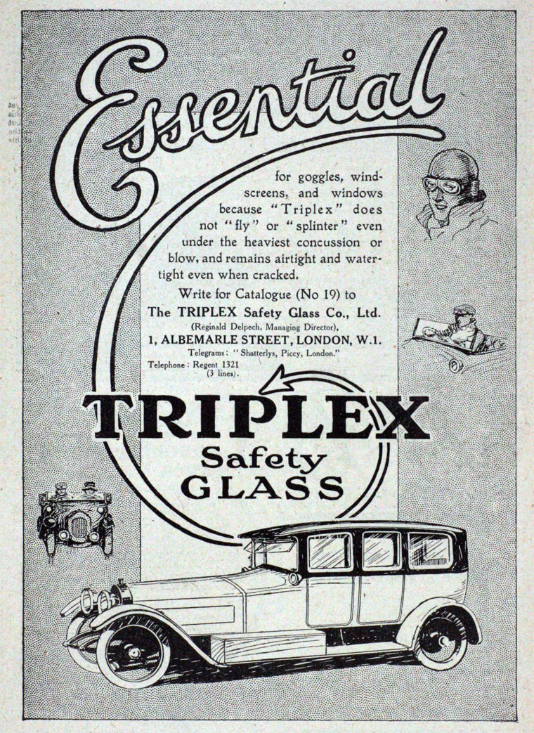
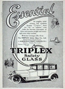 Advertisement 1919
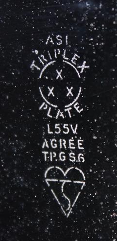
Safety glass windows for cars manufactured under the brandname TRIPLEX all received some form of manufacturing date code. This code was part of their trademark consisting of the word TRIPLEX combined with a circular formation around a triangular arrangement of the three X’s (= Triple X).
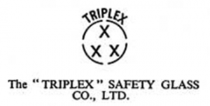 The TRIPLEX logo (with or without circle)
Post-war Triplex glass date codes (1945 – 1969)
Cars made till the late 1970’s can be dated by the code etched on the safety glass. Note that it dates the glass and is only an indication of the cars age, thereby assuming the glass is still original.
TRIPLEX safety glass is either named TOUGHENED or LAMINATED depending on the manufacturing process, but in addition the description PLATE has been introduced after the war for laminated windscreens (initially) intended for the USA. The date coding will be explained on basis of these three descriptions: TOUGHENED, LAMINATED and PLATE.
Year code for post-war TOUGHENED and LAMINATED Triplex glass
The year code systems (described below) was used over a number of decades leading to potential confusion if only the last number of a year had been indicated. Post war items are easily recognisable as from 1945 onwards the BS logo (or “kite mark”) was added below the original TRIPLEX logo.
The year code can be found in the nine letters that make the word TOUGHENED. One dot below a letter gives the year within a particular decade:
T O U G H E N E D
- T = 1
- O = 2
- U = 3
- G = 4
- H = 5
- E = 6
- N = 7
- E = 8
- D = 9
- No dot = 0 (or possibly a dot under a space after the last letter)
This code also works if you have a TRIPLEX windscreen with the (also nine letter) word LAMINATED instead of TOUGHENED.
Quarter code for TOUGHENED and LAMINATED Triplex glass
To further determine the approximate month of production, look for a dot above the TRIPLEX word in the logo on the glass, whereby only 4 letters have been used for the coding:
T R I P L E X
One dot above T, R, E, or X gives the quarter of the year the glass was manufactured:
- T = Jan, Feb, March,
- R = April, May, June,
- E = July Aug, Sept,
- X = Oct, Nov, Dec.
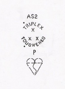 Example: 2nd quarter 1953 with BS logo
Year code for PLATE Triplex glass
A different coding system was applied for the post-war TRIPLEX laminated windscreens destined for the USA, whereby the year of manufacture was mentioned in two figures. The quarter coding system on basis of the word TRIPLEX was identical to the TOUGHENED and LAMINATED versions.
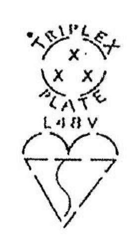
Windscreen 1st quarter 1948 Windscreen 2nd quarter 1955 Windscreen 3rd quarter 1959
Triplex branded glass (after Jan 1969)
The year indication is still identical to the TOUGHENED or LAMINATED system, but the month code changed. The month of manufacture is now indicated by the dots over the word TRIPLEX according a rather complicated system:


Example August 75 Month coding system Later logo with unknown Date Code system
History of UK Glass Manufacturers for the Automotive Industry .
British Indestructo Glass Ltd (to be investigated)
Pilkington (now owned by Nippon Sheet Glass Co., Ltd).
In 1929 Pilkington and Triplex formed a joint company to build a works at Eccleston, St. Helens. Pilkington gradually increased its shareholding in Triplex until by 1965 it became the majority shareholder.
In Pilkington’s Queenborough factory on the Isle of Sheppey in Kent the original glass products were made under various brand names like Triplex, Sigla, Bilglas or SIV. Today they can still supply products with the original trademark. The Queenborough factory has made classic windscreens for the aftermarket since the late 1950s, and still retains the vast majority of the tooling produced ’’in-house’’. The range consists of over 2000 parts including, AC Ace, 1953/63, Mercedes 220 1961/71, Aston Martin DB 4 1958/65 and MG’s to name a few. The specialist factory is certified according to BS EN ISO 9001: 2000 ensuring that all legal requirements are met.
 Advertisement 1948
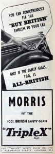
Triplex Safety Glass Co. Ltd. (Est. 1922).
In 1912 the need for the specialist production of safety glass led to the formation of the Triplex Safety Glass Company to manufacture in Britain on basis of certain French patents for laminated glass. The manufacturing process involved fixing some form of transparent material between 2 sheets of glass, thus triplex glass.
By 1922 “TripleX” manufactured at Hythe Road, Willesden, London, N.W.10. laminated and toughened safety glass, both plate and sheet, multi-ply and bullet-proof glass, curved safety glass, In addition they executed the shaping, forming and manipulation of “Perspex” and other thermoplastic materials.
Trade names: TripleX, Triplite, TriFlex.
 Tudor Safety Glass advertisement, 1956.
Tudor Safety Glass Co. Ltd. (Estd. 1935).
Spring Place, Kentish Town, London, N.W.5. Two toughening, ten bending furnaces: electricity, gas. Laminated and toughened safety glass, machinery glassware. Trade name: Vinylex. Tudor has been taken over by Triplex Safety Glass some decades ago and thus belongs to the Pilkington Group of companies.