Category Archives: 07. Front suspension
“Distance Gauge” suspension XK 140 & 150
1 Reply
Gauge for setting front suspension and steering geometry XK 140 and 150
Introduction
A correctly set front suspension (including steering geometry of course) is an absolute must for our XKs. This not only requires a correct ground clearance (torsion bar setting), but also caster and camber values have to be within specifications. The Jaguar Workshop Manual provides a wealth of information for the XK 120 and the Mk VII models on how to adjust the above mentioned items. It also gives additional information on a special “Distance gauge” to be used for setting the (initial) torsion bar position. This distance gauge replaces the shock absorber during the set-up operation.
The “Supplement to the 120 and Mk VII Service Manuals” lists the different settings for the successor models XK 140 and 150, however without giving any information about updated “Distance Gauge” dimensions. In many cases restorers therefore simply take-over the dimensions specified for the XK 120 (or Mk VII).
As the shock absorber dimensions and mounting positions of the XK 140 and 150 are different (compared to the XK 120) it is unlikely that the XK 120 Distance Gauge can be used 1 : 1 for these successor models. In addition the various parameters (ground clearance , caster, camber) mutually affect each other. As these parameters for the XK 120 are quite different, this will be another reason why the Distance Gauge of the XK 120 might be incorrect for setting-up the XK 140 and 150. This article tries to provide additional input in order to define the dimensions for a correct Distance Gauge for the XK 140 and 150.
The two functions of the Jaguar distance gauge.
These gauges have in fact two distances to be used for different purposes:
- The longer distance is used when the torsion bars have to be placed in the reaction levers after a complete restoration.
- The shorter distance can be used for setting camber and castor and is an “alternative method” of particular use during the restoration process to have a first set-up for the steering geometry when it is impossible to use the “full weight method” as described in the Manual.
For the Mk VII the gauge provides these two distances by choosing one of the two lower holes, whereas for the XK 120 a 2½” long separate distance piece has to be placed on the long threaded top end to get the longer distance.
For the “alternative” camber and caster adjustment method, Jaguar engineers (apparently) determined the exact distance between the two shock absorber mounts for the “nominal” chassis position under full weight. This front wheel position should be identical to the position obtained according the other described method of 7⅛” ground clearance at the “lower face of the most forward parallel section of the chassis frame” under full load. And it should also match the (later) introduced measurement of 11¼” ground clearance “from underside of front cross-member”.
Jaguar XK 120 distance gauge
The Jaguar Workshop Manual provides two drawings of the distance gauges for the XK 120 and Mk VII. The distance gauge for the XK 120 is basically a rod with a threaded top end and a ring welded at the bottom.
The XK 120 gauge consists of a 5/8” (16 mm) steel rod (length about 16” or 405 mm) with a (1”OD) washer welded about 3½” from the top. Using the existing top hole of the Shock Absorber, the top of the distance gauge has a (rare) BSF 11/16” -14 threaded part over a length of 3½” from the top. This BSF thread can be replaced by a UNF 5/8”-14 thread or even an M16x2 metrical thread. At the bottom a 1¼” x ⅝” (32 x 16mm) ring is welded with a mounting hole measuring 21/32”(16.5 mm). The spacer (or distance piece) has a length of 2½” and fits over the threaded top end. An outer diameter of 1” should be sufficient for the spacer. See all other dimensions in the above drawing.
Note that the washer (positioned about 3½” from the top) should touch the lower surface of the shock absorber bracket of the chassis when setting camber and caster.
Jaguar Mk VII distance gauge
As the Mk VII has a shock absorber with two horizontal mountings, the corresponding distance gauge is different. The top of the gauge is now a steel bush with a hole that corresponds to the diameter of the upper fixation bolt (or a bit larger: 15/32” or 12.0 mm). The bottom hole measures 21/32” (16.7 mm) and is identical for both the Mk VII and the XK 120. Note that two lower holes are provided: the lower hole (distance 15⅝”) to be used for setting the torsion bars (ground clearance) and the other (distance 13⅛”) for setting up the steering geometry. The XK 120 and the Mk VII (although different in weight) use apparently the same distance for setting-up the torsion bar position. As we will see later, the actual comparable distance for the Mk VII is larger because of the different (lower) position of the upper shock absorber bolt.
Different shock absorber mountings
The top mounting of the XK 140 & 150 is clearly different: horizontal bolt fixing versus vertical threaded stud on the shock absorber for the XK 120. This will have dimensional consequences for the distance gauge. If we assume that the geometry of the shock absorber bracket welded to the chassis is (more or less) identical for the XK 120 and its successors, then we have to compensate the dimensional difference because of the way the top of the shock absorber is mounted.
Where the distance gauge for the XK 120 touches the underside of the chassis bracket, a new distance gauge for the XK 140 and 150 should be in line with the Mk VII kind of fixation (using a horizontal top bolt). The distance between the underside of the chassis bracket (where the hole is for the shock absorber) and the (centre of the) horizontal hole in the chassis bracket for the XK 140 & 150 is about ⅞” or 21 mm.
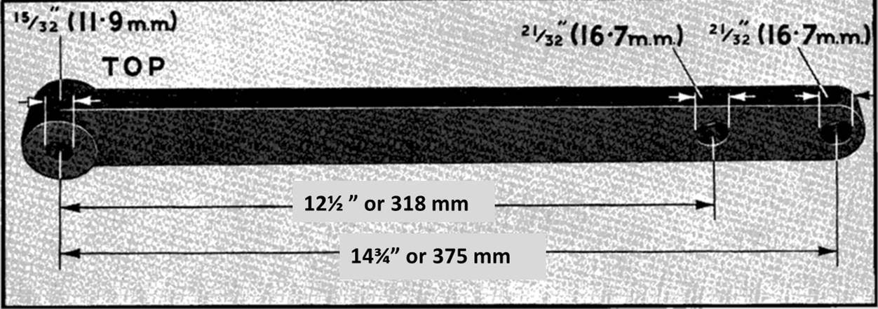
A new distance gauge for the XK 140 & 150.
The lowered position of the top bolt (⅞” or 21 mm) affects the dimensions of the new distance gauge.
- The longer gauge distance (used for initial torsion bars set-up) will be ((15⅝ – ⅞ =) 14¾” or 375 mm.
- The shorter gauge distance (used for setting camber and castor) will be (13⅜ – ⅞ =) 12½ ” or 318 mm.
Potential dimensional deviations of the gauge and their effects
We already mentioned that the XK120 and Mk VII apparently have the same gauge length for setting-up the torsion bars (ground clearance) although the required ground clearance and weight of the cars is different. However, using the aforementioned correction ((⅞” or 21 mm) the theoretical, comparable gauge distance for the XK 120 would be 14¾”or 375 mm. This implies that a lighter car requires a shorter gauge dimension for setting-up the torsion bars, which seems logical.
When the ground clearance was changed for the Mk VII (from 12¼ to 12⅝”) the distance gauge did not change. This may lead to the conclusion that the gauge length is not very critical. Remember that in fact the gauge is only used for the initial positioning of the torsion bar in the “reaction lever” and is always followed by an adjustment of the large bolt and barrel nut. Any deviation will have a limited effect as long as it still fits within the adjustment reach of the reaction lever and leaves sufficient room for adjustment.
For the steering geometry (camber and caster) the gauge is only used for setting the initial steering geometry during restoration or repair. Remember that the gauge distance here is only required to simulate the “nominal” wheel position as present under full load. We noticed a difference in gauge distance between the MK VII (333 mm) and the XK 120 (comparable: 340-21= 319 mm). This shorter gauge distance is apparently caused by two effects: a smaller king pin angle (5° for the XKs versus 8° for the MKs) and a larger caster angle for the XK 120 (initially 5° and later 3°), which again seems logical.
Finally: as the change of the castor angle for the XK 120 from 5° to 3° was no reason for Jaguar to change the distance gauge, the smaller step from 3° to 1¾° for the XK 140 & 150 may have an even smaller impact. Again we are dealing here with the initial set-up of the steering geometry, always to be followed by a professional check with special equipment.
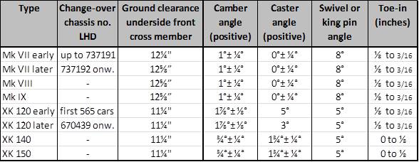
Survey of front suspension and steering geometry specifications
Wire wheels: worn hub and wheel splines
Wire wheels on Jaguar XKs
All Jaguar XK’s of the Special Equipment version were supplied with 16” wire wheels starting 1951. Also standard cars could have wire wheels as a factory option from that moment onwards.
 Early Rudge Whitworth wire wheel

Wire wheel fixation
Detachable wire wheels have a different way of fixation compared to normal disc wheels, as they are mechanically “connected” to the axle hubs in two ways:
1. In a rotational direction by means of driving splines (serrations) on the (stub) axle hubs and driven splines on the inner wheel centre.
2. In an axial way by means of a (threaded) locking nut preventing the wheel to become disconnected from the threaded axle hub.
This article will not tackle the subject of which wire wheel types have been applied by Jaguar over the years; see the appropriate literature for that. We do want, however, to emphasise the potential danger of wire wheel fixation systems after many years of use (and abuse) to the point where they may become even highly dangerous! In addition, some guidance is provided in checking whether a wire wheel can still be safely fixed to the car.
![clip_image002[4]](https://www.bobine.nl/jaguar/wp-content/uploads/2014/05/clip_image0024.gif "clip_image002[4]")
A – Locking thread on hub (left or right hand thread).
B – Driving splines on hub.
E – Driven splines of wheel centre.
Rudge-Whitworth fixation
The system of detachable and interchangeable wire wheels has been initially designed by John Pugh around 1910 but is better known under the (company) name of Rudge-Whitworth.
The resulting standardisation of detachable wire wheel fixations in Europe dates back to the 1920’s. The basis for this standard was the load to be carried per wheel and the required bearing diameter for that, resulting in a certain cross section for the hub. Note that the wheel type designation in the standard are basically structured around the (metrical!) dimensions of (then available) wheel bearings.
![clip_image002[6]](https://www.bobine.nl/jaguar/wp-content/uploads/2014/05/clip_image0026_thumb.gif "clip_image002[6]") Very early 1912 advertisement
Very early 1912 advertisement
![clip_image002[6]](https://www.bobine.nl/jaguar/wp-content/uploads/2014/05/clip_image0026.gif "clip_image002[6]")
Wear on splines and thread
Over the years the thread of the locking nut and the hub itself may wear but (even more important) the splines on the hub and in the wire wheel centre may wear to the extent that the construction eventually becomes unsafe. Therefore it is wise to regularly check them and more in particular during any XK restoration as the condition and history of axle hubs and wheels are unknown.
Four dimensions are of importance here and have to be checked:
1. The maximum allowed inner diameter of the thread of the lock nut
2. The minimum allowed outer diameter of the thread on the wheel hub
3. The minimum allowed outer diameter of the splined hub
4. The maximum allowed inner diameter of the inner wheel centre splines
Please note that wear of splines and thread is accelerated if the wheel is not fitted tightly!
Cross-section of Rudge-Whitworth hubs
The principle wheel type designation according the Rudge-Whitworth standard refers to the maximum size of an outer wheel bearing (in millimetre) which can be used with that hub. The actual hub diameter is measured across the outside of the splines on the axle hubs ( not the wheel splines).
|
Wheel Type |
Actual hub diameter |
Number of splines |
Spline length Short Hub |
|
35 |
52 |
62 |
36 |
|
42 |
62.5 |
75 |
37 |
|
52 |
73 |
88 |
37 |
|
62 |
82.5 |
100 |
57 |
|
72 |
92 |
112 |
55 |
|
80 |
102 |
124 |
58 |
|
90 |
111.5 |
136 |
56 |
|
100 |
123 |
150 |
59 |
|
120 |
137 |
168 |
63 |
Two wire wheel types are normally used on British sports cars: type 42 and 52. Jaguar opted for their post-war cars for the Type 52 wire wheels. The (course) thread of Jaguar wire wheels has a top angle of 60° and a pitch of 8 TPI (or 3.2 mm).
 Rear wheel splined hub Jaguar XK 140

Dimensional requirements for Type 52 wire wheels: worn or still OK?
Further to the aforementioned important testing criteria, the survey below gives specific information regarding when a splined hub, wire wheel or locking nut should be replaced.
- The locking nut should be checked for wear on the (internal) thread. If a cylinder with an outside diameter of 2.627” or 66.7 mm should fit in the locking nut, wear has progressed to the extent that the locking nut has to be replaced.
- If a tube with an internal diameter of 2.707” or 68.8 mm fits over the thread of the axle hub, wear has progressed to the extent the complete hub has to be replaced.
- If a tube with an internal diameter of 2.840” or 72.1 mm fits over the splines of the axle hub, the complete hub has to be replaced.
- If a cylinder with an outer diameter of 2.790” or 70.9 mm fits in the internally splined wheel centre, the complete wire wheel has to be replaced.
Note that the above dimensional requirements are no more than minimum requirements! As an example: wire wheel constructions fulfilling the above requirements have a remaining overlapping contact height of the splines of no more than (72.1 – 70.9 =) 1.2 mm. Although the contact surface is of course larger due to the 60° V angle of the spline and the length of the spline (here 37 mm), in comparison a new type 52 spline has a contact height of 72.9 – 70.2 = 2.7 mm, meaning that the (safety?) margin has been more than halved.
So don’t use any hubs or wheels with spline dimensions below the above given minimum requirements!