Category Archives: 02. Engine
Flexible Breather Pipe Routing on XK’s
Leave a reply
Flexible breather pipe routing on XK’s
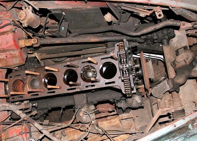
XK120 early (prior to engine No. 660227 and 670774)
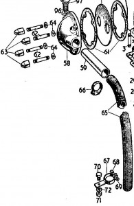
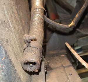
The routing of the Flexible Breather Pipe (Jaguar C.2485) is not completely clear but the information in the XK 120 SPC gives sufficient guidance. The top of the pipe is connected to the Front Cover / Breather Housing C.2485 by means of a Cheney 1A Clip with part number C.2905/3. For the first 1000 engines, a special Clip (C.2442) was used to hold the bottom end of the flexible breather pipe to the chassis. Most likely, the fixation method of this Clip was identical to the one of the later clip (see next chapter). It is unclear what the difference is between the early and the later clip version. According the SPC the Clip is fixed to the chassis using an ( 5/16″ ANF/UNF x ½ “) setscrew with nut and shakeproof washer. This seems not identical to the method described for the later Clip. Conclusion is that the breather pipe runs between generator and inner wing valence downwards and that the bottom of the flexible breather pipe is held by Clip C.2442 fixed at the LH chassis, possibly between Radiator Rod and its Bracket.
The length of the early Flexible Breather Pipe C.2485 is not mentioned, but we may assume (after comparison of the routing of the XK 140 and 150; see hereafter) a length of around 30”.
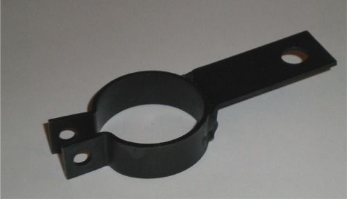
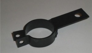 Clip C.4728 for breather pipe XK120

XK120 (from engine No. 660228 and 670775 onwards)
The early XK 120 Clip C.2442 has been replaced by a new version with Jaguar part number C.4728. The differences between the two remain unclear.
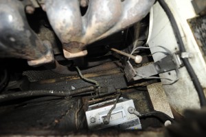
The bottom of the pipe is fixed by Clip C.4728 which is positioned between the bottom end of the Radiator Rod and its Bracket welded on the LH chassis rail. To be confirmed by other examples.
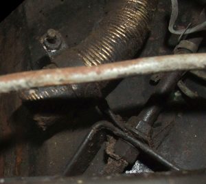
 Fixation of Clip C.4728 between Radiator Rod and Bracket (photo Tadek Malkiewicz)


The flexible breather pipe itself also changed, as it received a new part number C.2485/1, possibly due a change in length. As the XK 140 uses the same pipe, we know that the length is about 31”.
XK 140 (all versions)
According the XK 140 SPC, the only change of the Flexible Breather pipe relates to the introduction of a standard Lucas (Cable) Clip C.1040/21 or Lucas 900401, replacing Jaguar Clip C.4728. This Lucas clip 900401 is mentioned in the 1954 Lucas Master Catalogue and has an inner diameter of 1⅛” (32 mm) and a 5/16” (8 mm) fixation hole.
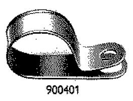
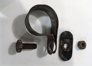 Photo Lucas Catalogue Fixation of Clip (Photo Harv McCullough)
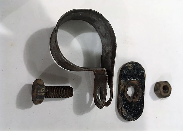
The routing and length of the flexible breather pipe is different from the one for the XK120. The first part of the routing is still the same (from the Breather Housing over the Generator downwards), but towards the end of the pipe it runs over the LH chassis rail further to the back. Clip C.1040/21 (Lucas 900401) is positioned under the setscrew that holds the inner wing valence to the L-bracket welded on the LH chassis rails. We have 3 photos to show this routing.
 Clip C.1040/21 with the fixation setscrew at the underside. (Photo Bob Knynenburg)
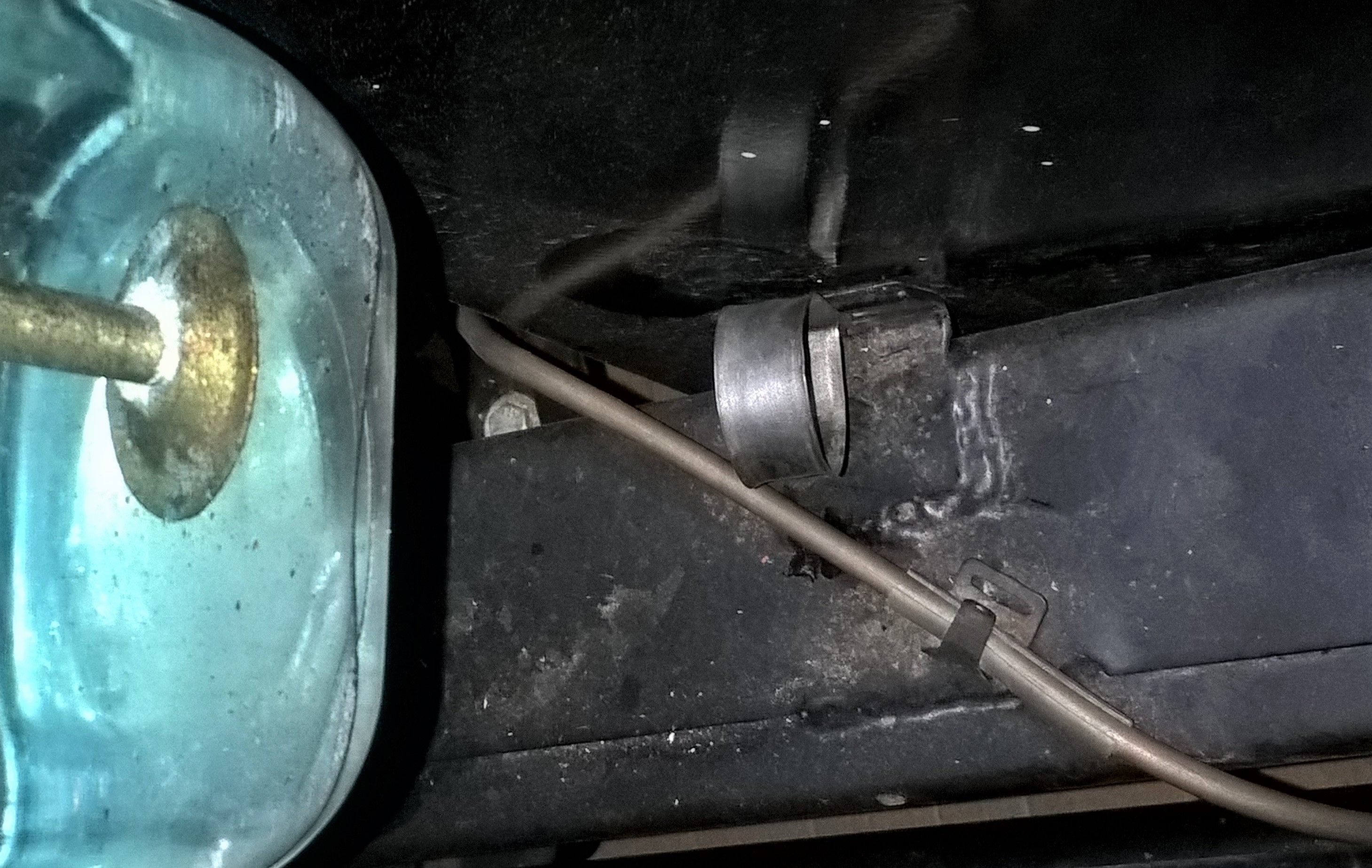
Note that Clip C.1040/21 is mounted with the loop upwards, as there is insufficient space between bolt hole and chassis rail. This implies that the flex pipe runs about 1” above the chassis rail at the L-bracket.
 Original RHD XK 140 DHC (Photo Roger Payne)

The first photo is from an original (11,000 miles only) RHD XK 140 DHC. It shows that Clip C.1040/21 is mounted on the L-bracket holding the inner wing valence. The SPC indicates a ¼” UNF x ½“ setscrew is used for this, but a longer ¼” UNF x ⅝“ setscrew may have been used, as the setscrew length has to deal with the additional thickness of Clip C.1040/21.
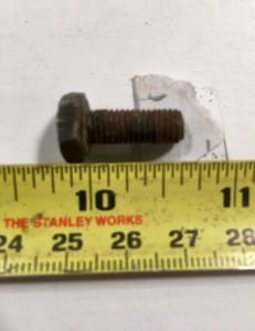 Longer setscrew ¼” UNF x ⅝“ (Photo Harv McCullough)

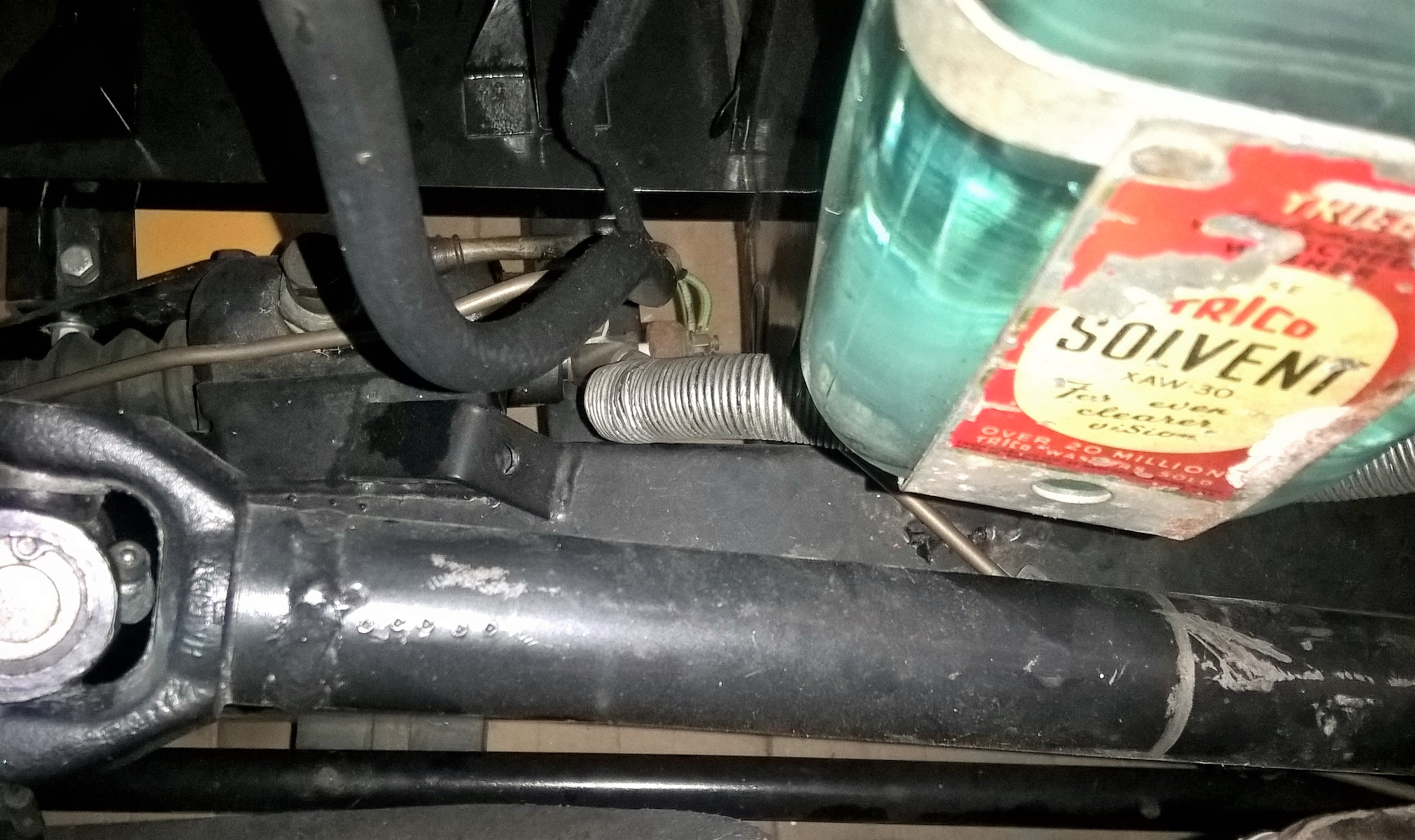
The Flexible Breather Pipe ends just in front of the radiator stay rod bracket on the chassis, as used on early XK 140’s (until about May 1955). We can see the end of the flexible pipe on this DHC (and OTS as well) as the washer bottle is further to the rear. For the FHC, the end of the pipe is partly hidden under the washer bottle.
 LHD XK 140 FHC (Photo as advertised on EBay 2007)
Above is an older photo showing the same arrangement on an unrestored LHD FHC. When looking in detail, Clip C.1040/21 can be seen on the L-bracket holding the inner wing valence. As said earlier, on FHC versions the flex pipe runs under Washer Bottle. The pipe length is about 31” for all XK 140 models.
On all versions, the Flex Pipe ends about 4” after Clip C.1040/21. On the LHD FHC (and probably on the DHC and OTS) versions there is the possibility to bend the bottom end of the flex pipe downwards, so oil fumes and droplets may drip on the road; in case of the LHD FHC this is near the Master Brake Cylinder.
 Flex pipe curved downwards near Master Cylinder on LHD FHC (Photo Bob Knynenburg)
XK 150
The XK 150 SPC defines for the flexible breather pipe (new part number C.15400) a length of 33” which is 2” longer than the one for the XK 140. The only other change in comparison with the XK 140 is the addition of one extra Lucas clip C.1040/21, located at the inner wing valence. The XK 150 SPC defines only one fixation bolt for the second (upper) clip, but the SPC for the later XK 150S lists in fact two fixation bolts: one for the upper and one for the lower Clip which seems the most logical version. The bottom clip is positioned and fixed as per XK 140. The exact fixation point of the upper clip is unclear, possibly on the LH support bracket for the inner wing valence.
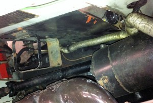 XK 150 routing is identical but with 2nd clip

This photo shows the pipe routing with a second clip where the pipe meets the inner wing. The bottom clip is clearly visible just below the Washer Bottle Bracket.
Spark plug caps and suppressors for Jaguar XK’s
Introduction
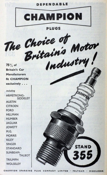
From 1934 onwards Jaguar used Champion spark plugs for their pre-war (SS) engines. This may also have influenced them to source spark plug caps (or HT cable terminals) from Champion after the war.
 Advertisement 1951, mentiones Jaguar
History of Champion in UK
Champion started it spark plug activities in 1908 in Boston, USA and then moved to Toledo, Ohio, USA in 1910. In 1920 Champion moved across the Atlantic and established the Champion Sparking Plug Company Ltd. in England with their offices at 83, Pall Mall, London. Their UK industrial facilities were at Hatton Cross, Feltham, Middlesex (near London) and stayed there until it had to move due to the extension of Heathrow Airport in 1968. Thereafter the Champion Spark Plug Company operated an automotive components factory on Arrowe Brook Road, Upton near Liverpool employing at one time over 1,000 people. It was closed in 2006 and the production was transferred to Italy.
Early spark plug terminals: Jaguar C404
Pre-war and first post-war models like the Jaguar MK IV and MK V used an uninsulated horizontally positioned terminal made of tempered (tinned) brass (Jaguar part number C404), which was secured by a nut on the threaded end of the spark plug. The manufacturer of these terminals is unknown.
 Early spark plug terminal C404 (Courtesy Rob Reilly)
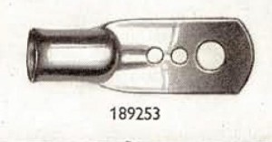 Lucas HT terminal end 189253

Lucas HT terminal end 189253 for 7 mm cable seems identical to Jaguar C404 and we may conclude that these were supplied by Lucas.
Note that all XK engines as used for the XK120, 140 and 150 had “straight” spark plug caps, apart perhaps from some early (experimental) engines that had horizontal connections for the HT wires.
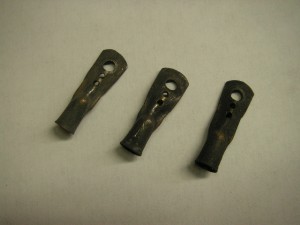
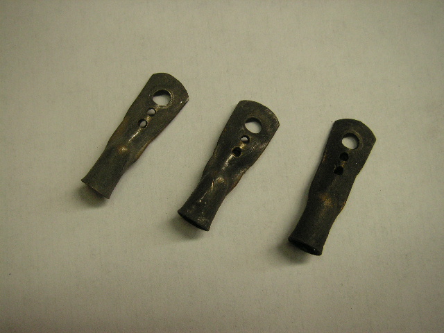
Jaguar C1575: uninsulated straight terminal
The early Jaguar XK 120 (up to engine number W6372; late October 1952) had a spark plug terminal Jaguar part number C1575, which is in fact an uninsulated straight metal sleeve connected to the HT wire. This method of fastening the HT cable to the spark plug terminal is different from all later systems: the copper core of the HT cable was mechanically connected to the brass sleeve that fits over the spark plug end.
 C1575 uninsulated straight terminal
 Example of an uninsulated straight spark plug terminal

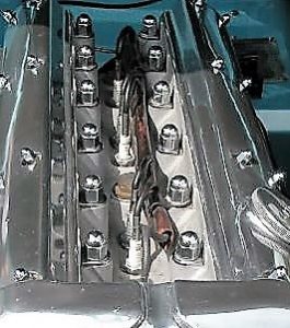
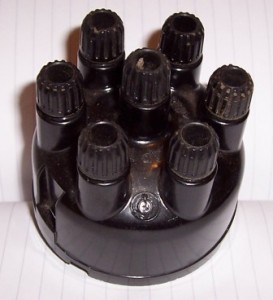
Up to November 1952 XK 120’s had a distributor cap (Lucas 415708) with horizontal cable outlets: the HT leads entered through holes on the side and had a screw on the inside that fastens down on the leads. So the early HT cables had a metal sleeve at one end and nothing at the other end.
 Lucas 415708 for early XK 120
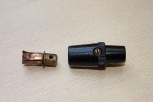
Jaguar C5479: Champion HTC cap
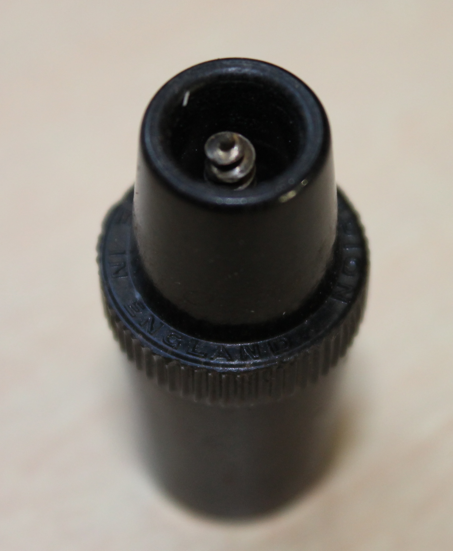
From late October 1952 onwards the XK120 received a spark plug cap made by (or made for) Champion. Jaguar changed over to an insulated (Bakelite) spark plug cap type replacing the bare metal C1575. The original early version (that we know now as the Champion HTC type) had tiny embossed letters on the rim in the middle: “Champion Made in England”. They have an internal, fixed screw tip and are screwed into the centre core of the HT wire ends.
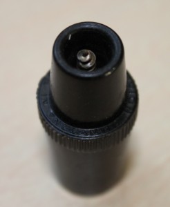 Text “Champion Made in England”
This Champion plug cap was used on the later XK120, XK140 and XK150, unless a suppressor plug cap was required (see hereafter).
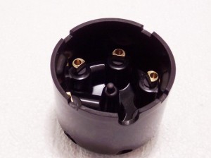
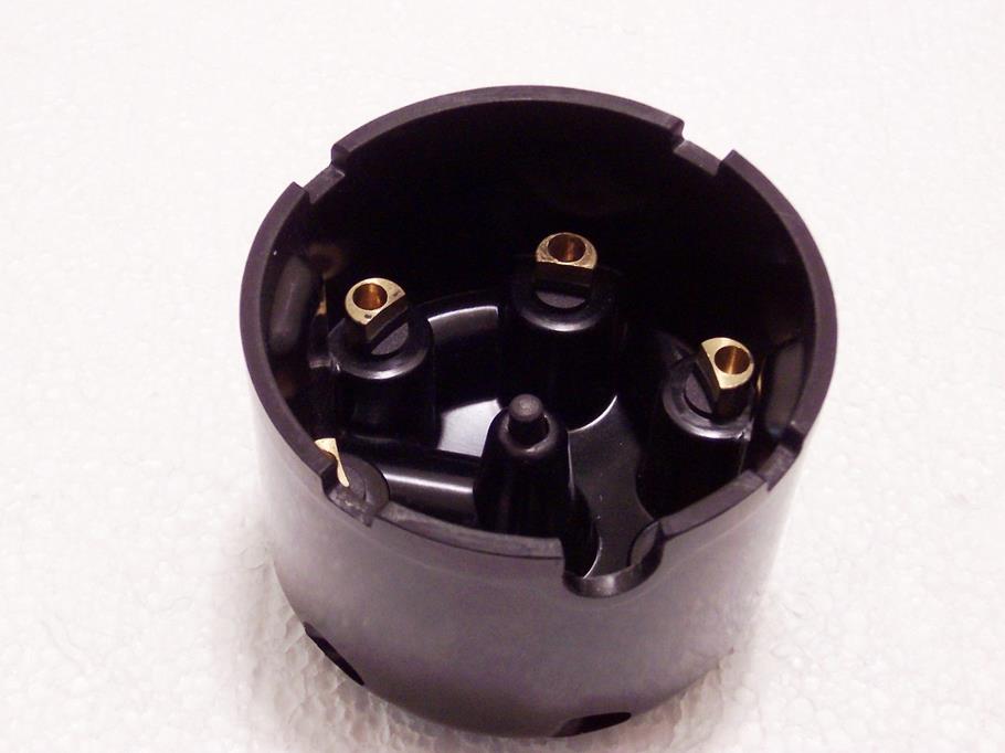
 Lucas 407043 for later XK 120

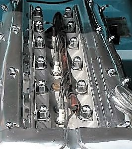
About the same moment the fastening system with “moulded nut and split-washer” for the HT wires to the distributor cap was introduced (late November 1952) when the XK changed over to a distributor cap with vertical entry (Lucas 407043) and a different routing for the HT cables. So both ends of the HT cable got new “terminals”.
Later Champion HTC 2 plug caps (replacement for original)
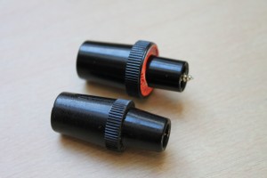 Difference between original and new HTC 2

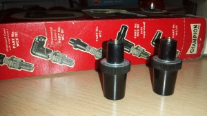
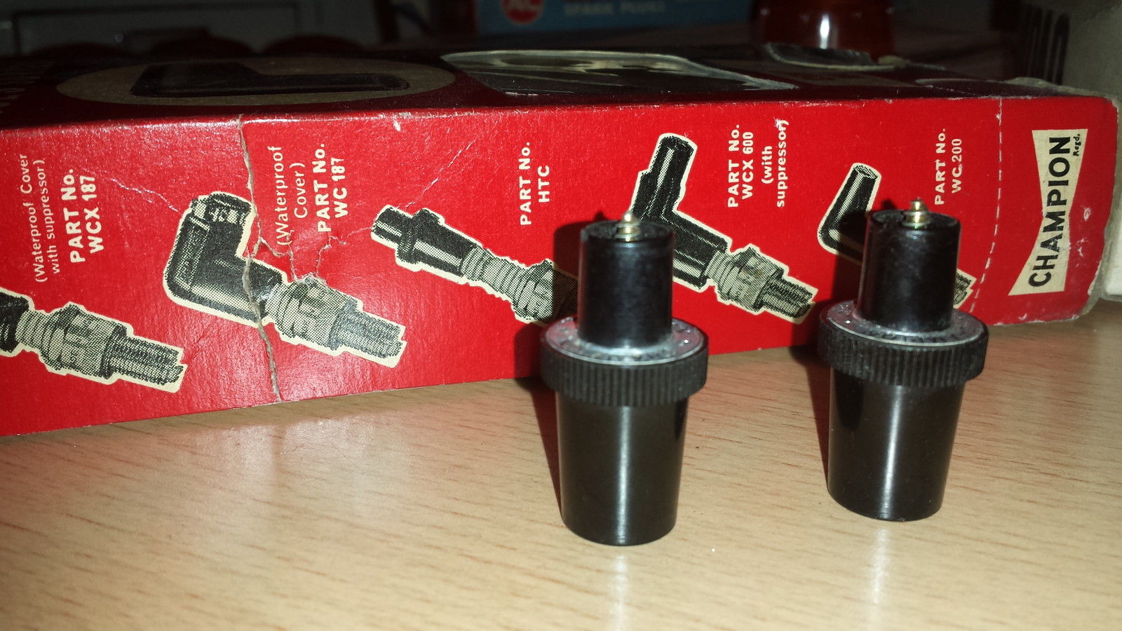
A new HTC version was introduced in the 70’s. These are slightly larger in diameter, have a wider knurled ring and the embossing (Made in England) has been replaced by an initially grey and later red printed paper ring with two times “Champion” on it. Apart from the missing embossing, the newer versions can be easily recognised as the black housing has less taper at the plug end, whereas the other end has almost no taper at all. Both are of the same length but the pin that screws into the HT Cable core protrudes further in case of the newer versions (see photo above).
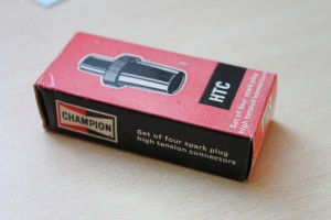
As mentioned above, there are two basic productcversions: the original and the replacement version. The latter can be divided in the initial “Grey ring” version followed by the “Red ring” version. The difference is also shown in the boxes that belong to two later replacement versions:
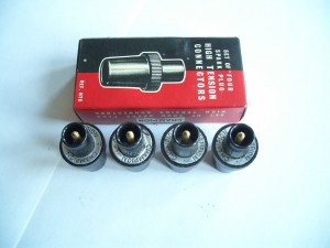
 “Grey paper ring” box with description “REF. HTC” or “Part No. HTC”
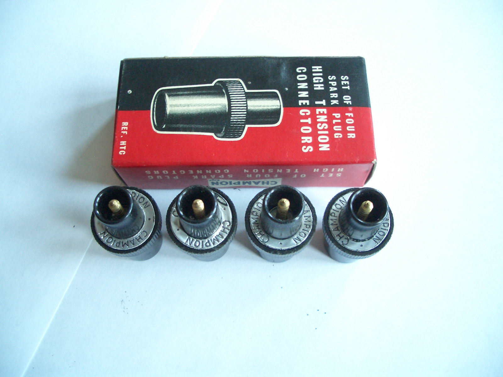
Early versions had a Grey paper ring and can be recognized by the “slotted” screw for connecting the cable core, that can be seen on the inside of the metal part that snaps over the spark plug. Note the text on the box “spark plug high tension connectors Ref. HTC”. We may conclude from this that the early “grey ring” version was still called HTC instead of HTC2.

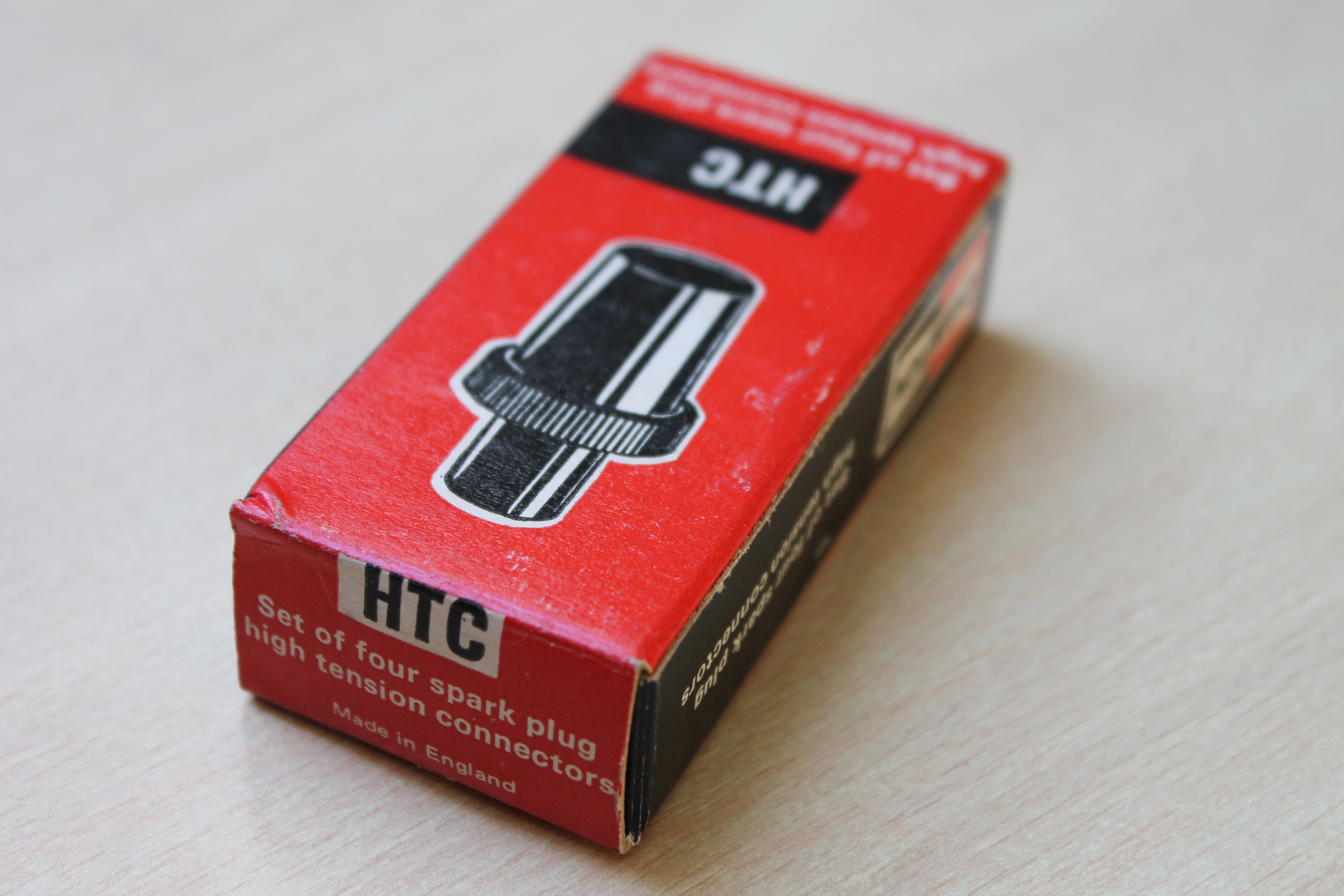
 Box for later “Red paper ring” versions with model number “HTC”

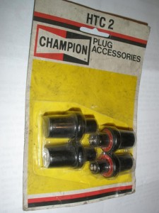 Blister with “HTC-2” spark plug caps

Note that the “Red paper ring” version is not named HTC-2 on the box. These later Red paper ring versions can be recognized by the “crosshead” screw on the inside of the metal part that snaps over the spark plug.
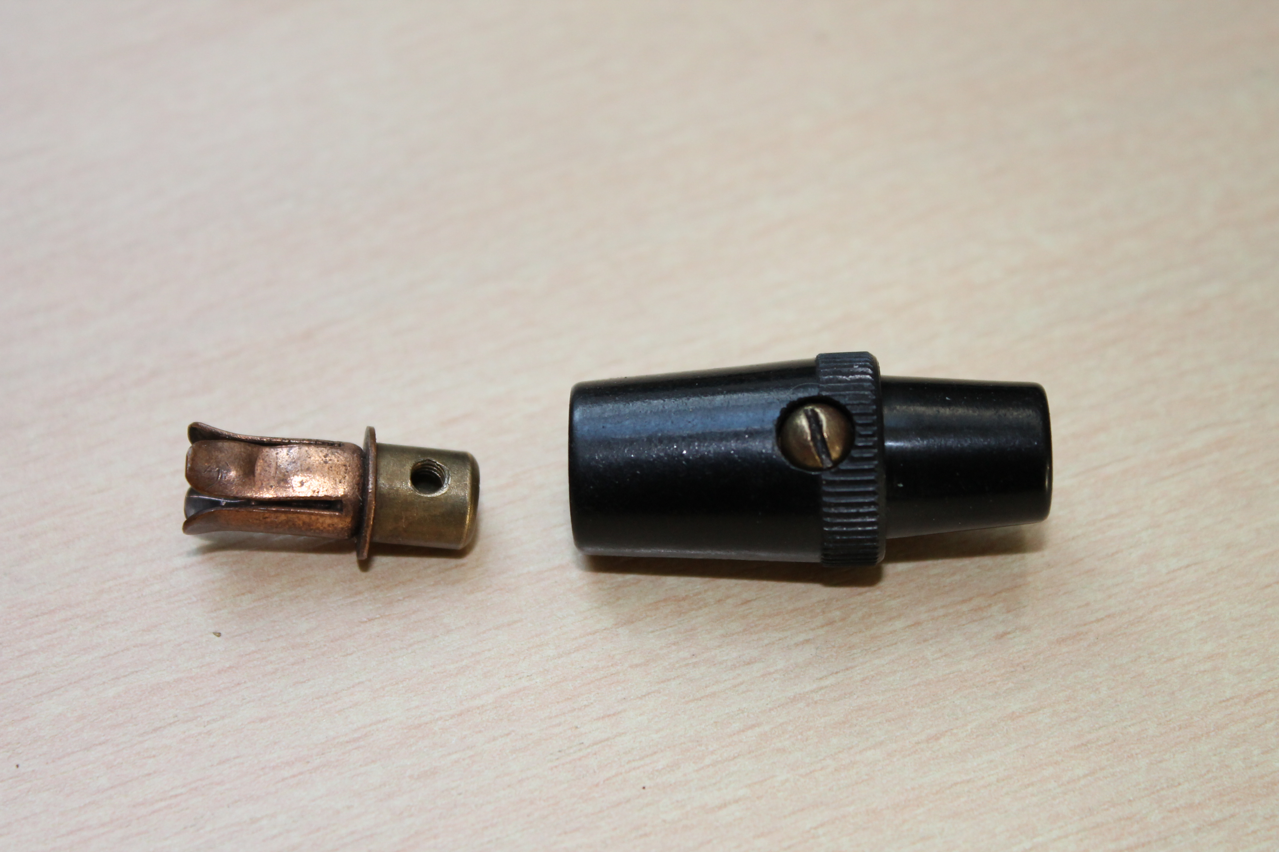
Alternative Champion HTC cap with fixing screw
Another Champion “HTC cap type” that occasionally comes for sale, has a fixed, internal brass piece into which the exposed lead wire end is fitted and then held in place with a set screw. This version was applied by BMC (part number AEC 388). The mould used for the Bakelite housing is apparently the same as for the initial HTC cap as the embossing (Made in England) is identical.
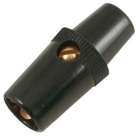
 HTC with screw
As far as we know this version was never used by Jaguar.
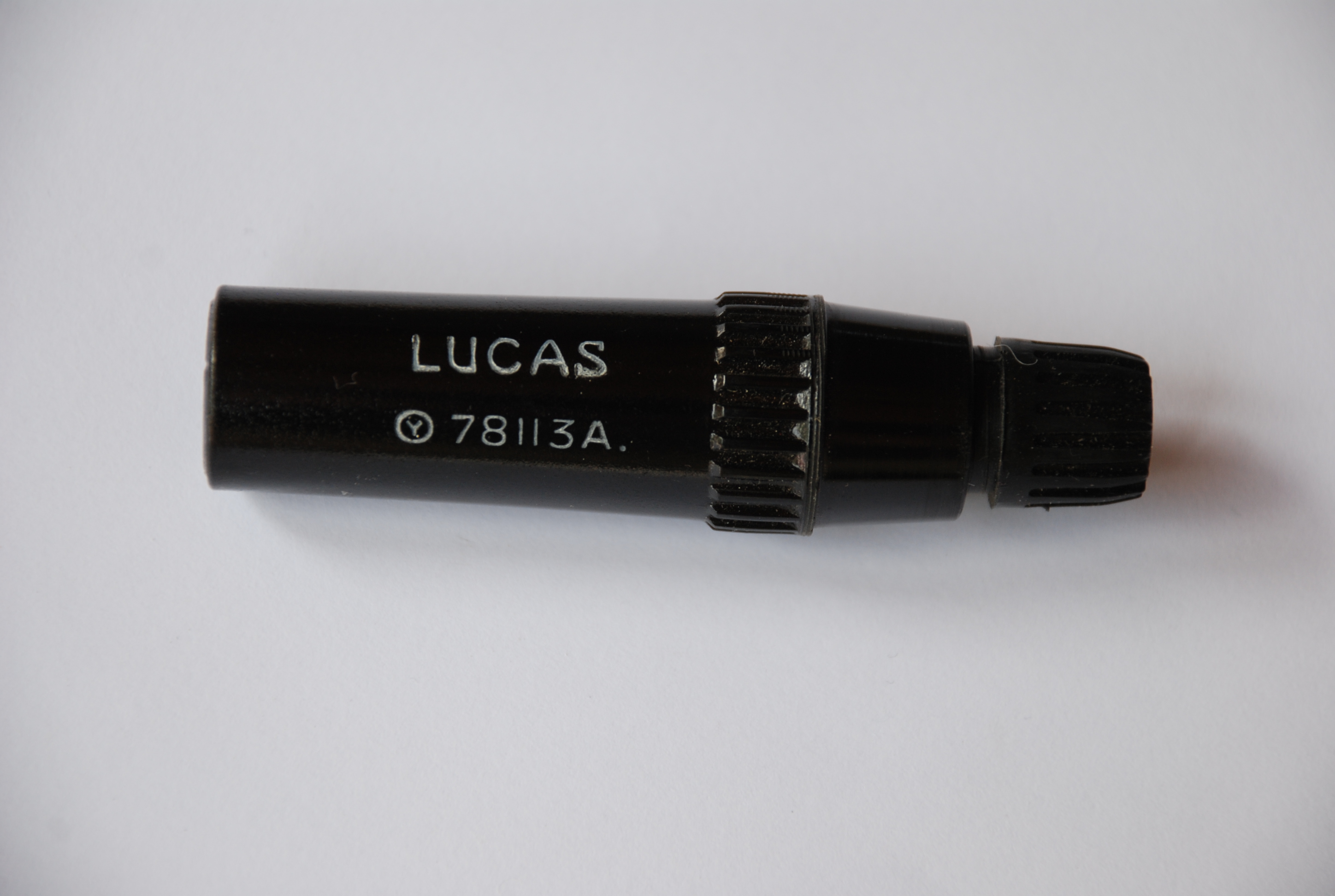
Jaguar C.8306 Lucas 78113A spark plug suppressor cap
With the arrival of TV in the early 1950’s in the UK (and elsewhere of course) the need for a “suppressor” version arose. Initially the Lucas type WS5 spark plug cap could be installed as “optional” and wasn’t applied as the “standard” plug cap.
Service Bulletin SB131 (dated August 1953) however had the following information: Note that all Home Market and Home leave cars are now fitted with ignition suppressors. So we may conclude from this that the majority of the exported cars still had the Champion HTC spark plug cap installed.
The 1960 XK150 SPC clearly states that the C.8306 spark plug suppressor cap was now installed on all Export versions. The exact implementation date is as yet unknown, but probably in the period 1957 – 1959.

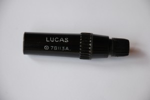 Suppressor Lucas 78113A (photo: Roger Payne) Lucas 78113A has resistance of about 18 kΩ
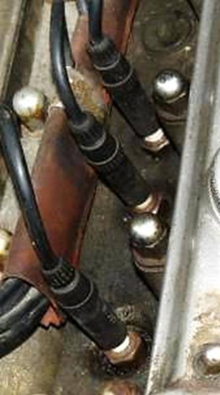

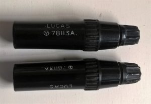 Lucas suppressor 78113A in original box Two versions of 78113A with text 180 degree rotated
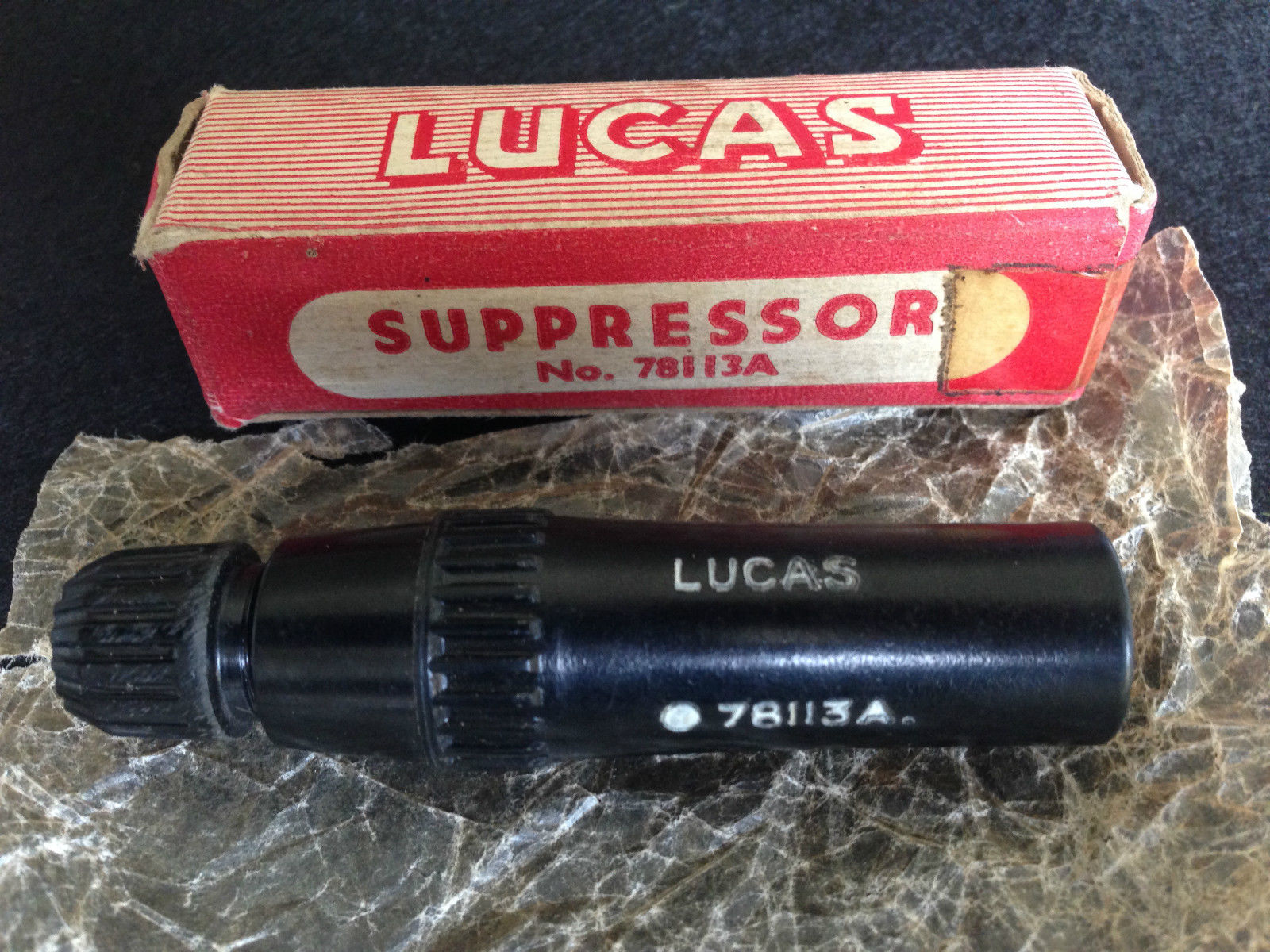
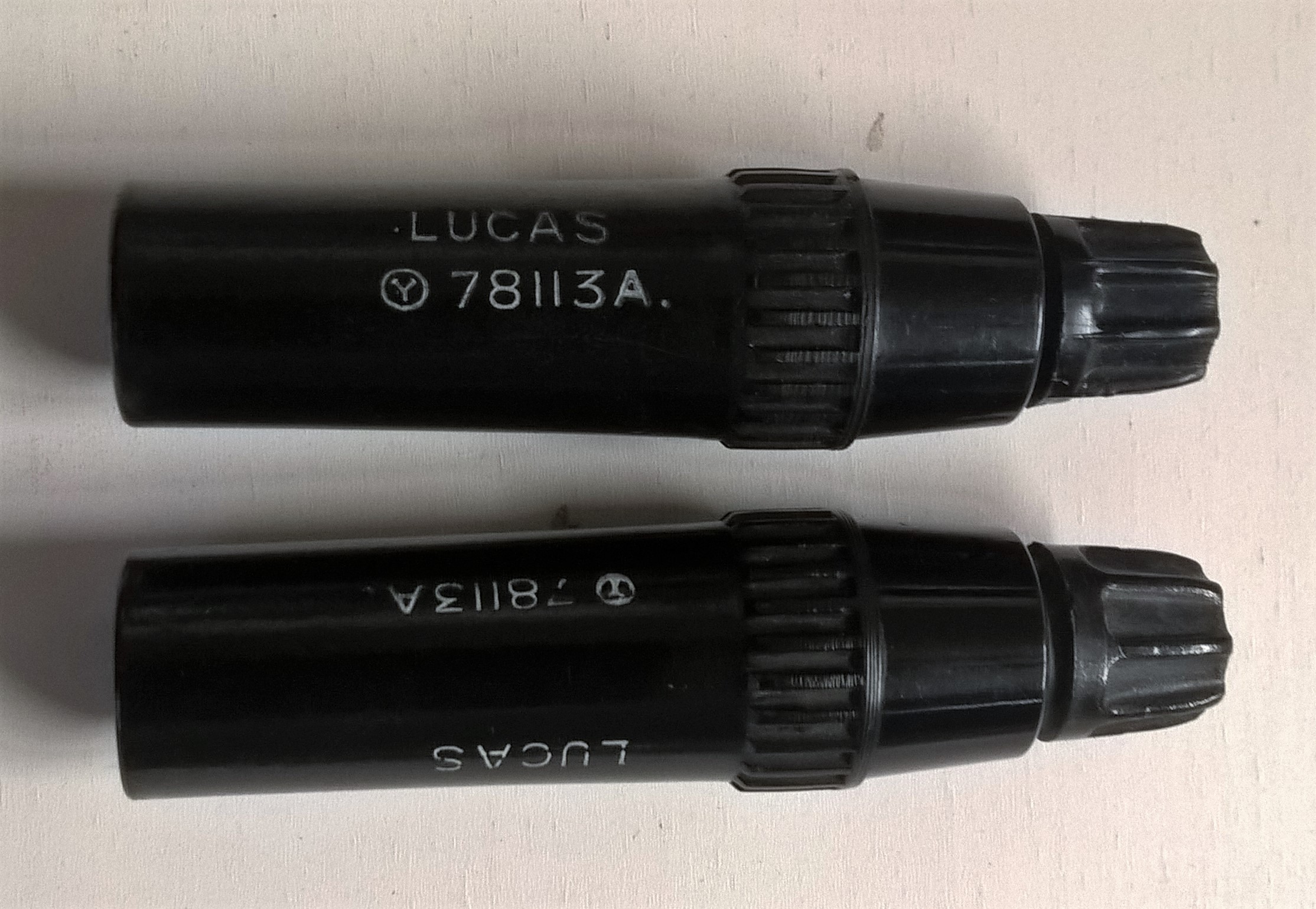
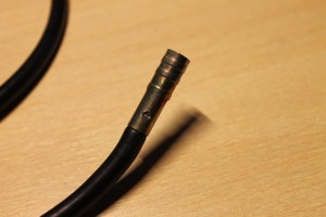
The resistance of this Lucas suppressor is about 18 kΩ. The HT lead connection is similar to the distributor cap installation with “moulded nut and split washer”. Note that there are two different versions of this suppressor whereby the text has been rotated 180 degrees. The part number itself did not change. The photo above left is identical to the bottom version on the photo right and is probably the first generation: the font is smaller and it smells like “Bakelite”.
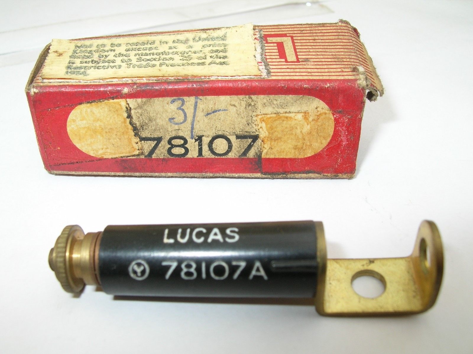
For older cars with an uninsulated brass terminal secured by a nut on the threaded end of the spark plug, Lucas introduced a special suppressor 78107A . After the existing nut has been removed, this suppressor is positioned on the spark plug (either horizontally or vertically) and the nut is placed back. The brass terminal of the plug cable is attached to the other end of the suppressor.
 Lucas suppressor 78107A for earlier cars
Other types of suppressors
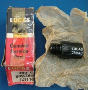
As mentioned above, most XK’s left the factory with Champion plug caps without suppressor. The XK120 Spare Parts Catalogue, however, refers to Suppressor C8046 installed on the Distributor Cap of all Home Market XK120s in addition to the Plug Suppressors C8306. Reference is made of Suppressor C8046 (Lucas 78114A) described as an alternative solution for the Lucas 78113A spark plug suppressor cap . This single suppressor, with a resistance of about 10 to 15 k Ω, is positioned in the centre connection of the distributor cap. In this way the spark from the coil is suppressed before it enters the distributor cap. A warning is given not to install this suppressor in the connector of the ignition coil: “If fitted to the coil (instead of the distributor cap) there will be a ¼”gap causing ignition failures”
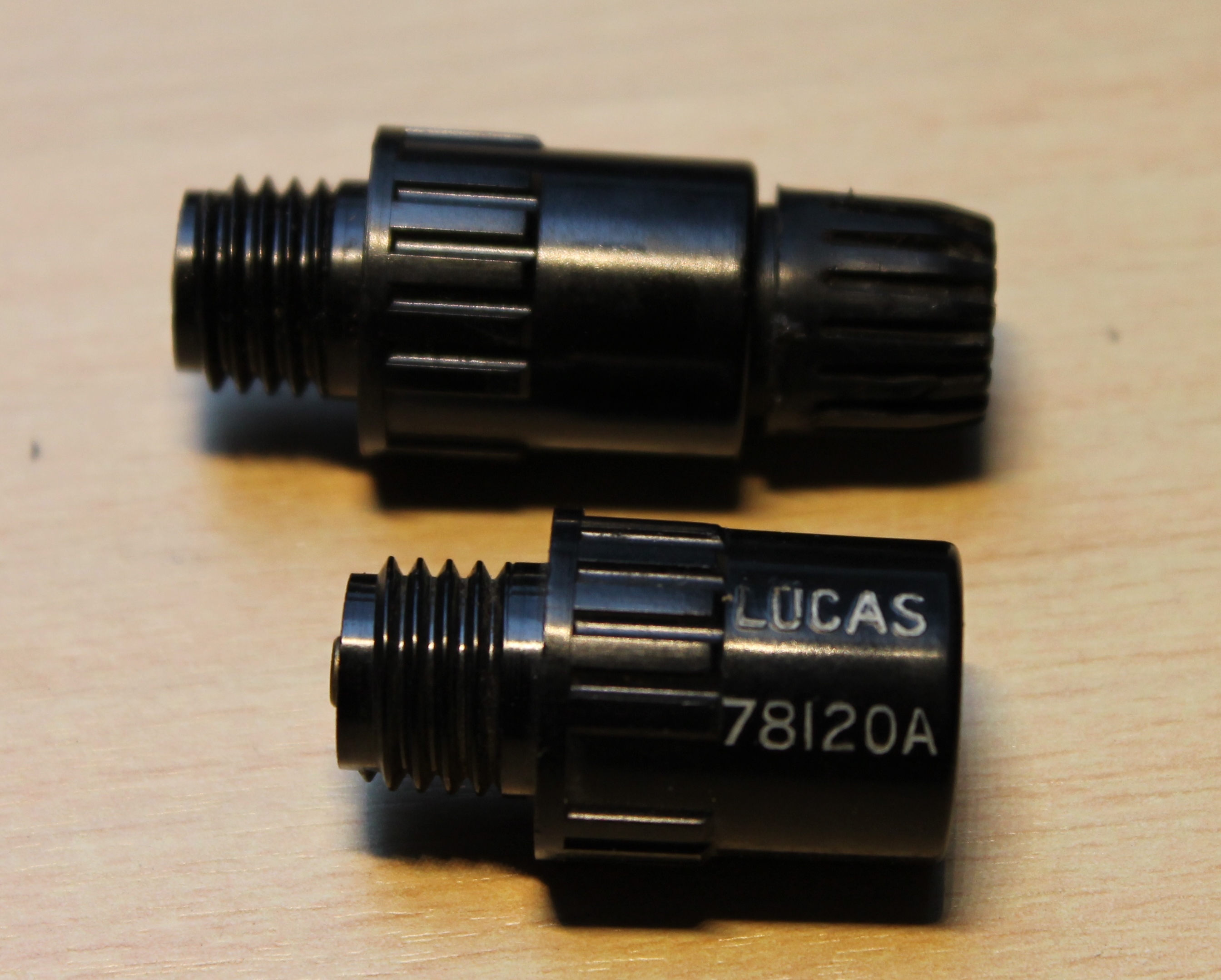
A second version of this distributor cap mounted suppressor is Lucas 78120A which is identical to Lucas 78114A however with a lower resistance of 6.3 k Ω.
 Suppressor C8046 for centre contact distributor cap.

Identical cap-mounted suppressors (but also many other suppressor types) have been manufactured by Erie Resistor Ltd of Great Yarmounth (UK). The Erie D8 is an exact copy of the Lucas 78120A suppressor which may lead to the conclusion that Erie actually manufactured these for Lucas.
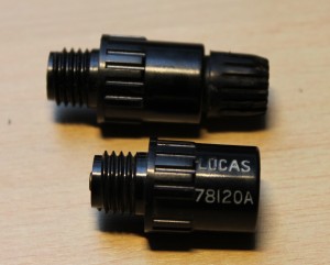 Lucas 78120A with identical Erie D8 (with nut) above
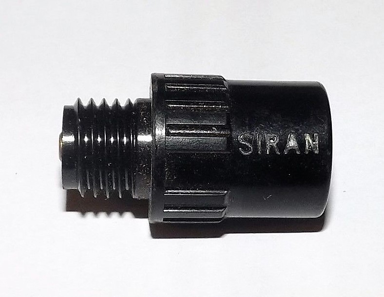
There were a number of other companies supplying the same suppressor, like Durite and SIRAN. Durite was a British manufacturer of automotive electrical equipment. SIRAN Accessories was a 1960’s British company based in Hove, known for its car instruments and switches. Resistance values are unknown.
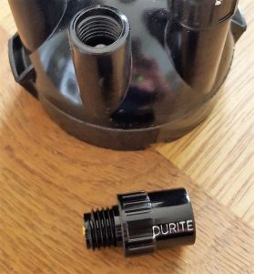
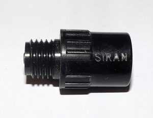 Suppressor supplied by Durite Same suppressor now branded SIRAN

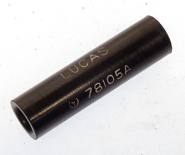
Another version was the “cable type of suppressor” as e.g. Lucas 78105A. This type is normally placed in the cable from HT Coil to Distributor cap and is screwed in the copper core of the HT lead. But it is sometimes used in every spark plug lead.
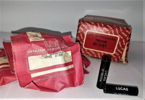
 Lucas cable type suppressor 78105A

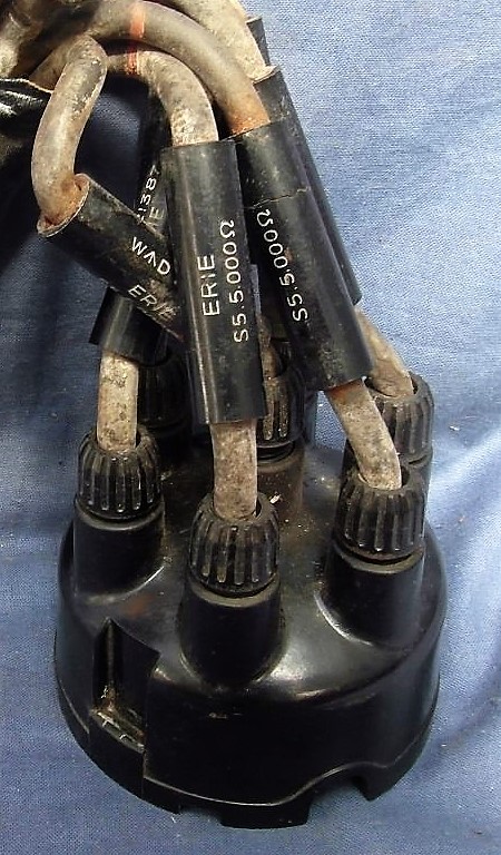
The Erie Resistor Lid. also provided a cable suppressor (probabale code number WAD.1738) with 5000 Ω resistance. An example is shown below with a suppressor in all 6 HT leads.
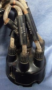 Erie Cable type suppressor of 5 kΩ
In May 1957 Jaguar Saloons received a new DMBZ distributor with a distributor cap with “built-in suppressor”. Reference is made of Service Bulletin No. 212 of May 1957 which states: ” Note that the DMBZ type of distributor fitted to the above models incorporates an inbuilt suppressor. The suppressor normally fitted in the centre terminal post of the distributor is therefore unnecessary and must not be fitted.” The centre terminal post suppressor as refered to is the above described Lucas 78114A (or Lucas 78120A version).
Crankshaft Damper Assemblies for XKs
Crankshaft Torsional Vibration Damper Assemblies for XKs
Background information
Certain high speed in-line internal combustion engines are prone to torsional vibration of their crankshafts: the straight six and straight eight engines being particularly prone to this problem due to their long crankshaft length. A crankshaft vibration damper is required for which two basic concepts are applied: the frictional vibration damper (e.g. RR and Bentley) and the rubber bonded damper.
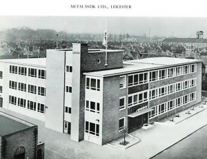 The Metalastik factory in Leicester (UK)
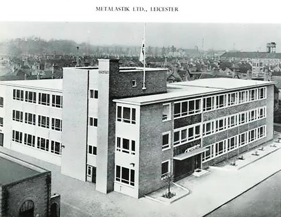
Mac Goldsmith (Max Goldschmidt) started his engineering company near Frankfurt (Germany) in 1925. He moved to England in 1937 and formed the Bundy Tubing company in Welwyn Garden City (north of London), manufacturing copper coated tubing. About a year later he established the Metalastik company in Leicester. Another famous Leicester rubber manufacturer, the John Bull Rubber Company, merged with Metalastik Precision Rubbers in 1955. In 1958 the group became part of the Dunlop Rubber Company Ltd. The Metalastik trademark is still used today by its new owner Trelleborg.
In the late thirties the Metalastik company introduced an improved and simpler design which is the rubber bonded metal disc type and this remained standard on many engines to this day. The Metalastik type is not just a damper, but rather a tuned and damped ‘vibration absorber’. The vibration absorber is a secondary inertial mass and spring stiffness, tuned to the first natural torsional frequency of the crankshaft assembly; this results in two new natural frequencies, one above and one below the tuned frequency, and a marked reduction in the amplitude of oscillation of the crankshaft at the original natural frequency. The inherent damping of the rubber ensures that the amplitude of oscillation of both the crankshaft and the absorber at the two new natural frequencies are within acceptable limits.
The 3442 cc Jaguar XK 6-cylinder engine of 1948 and most subsequent versions of the Jaguar XK engine used a proprietary Metalastik vibration damper to protect their crankshafts from potentially damaging torsional vibrations. To quote William Heynes in 1953, “The Metalastik damper consists of a steel plate to which is bonded, through a thick rubber disk, a malleable iron floating weight. Variations of the weight, rubber volume and mix, give these dampers a very wide field over which they can operate.”
The rubber bonding of the original Metalastik dampers is prone to disintegration through age and oil contamination. The rubber compound hardens and breaks up, which means that the damper is no longer absorbing crankshaft vibrations. Jaguar advises a deflection of the damper weight in relation to the crankshaft of no more than ½°; the torsional vibration damper should be renewed when the deflection is more than this figure.


Oct ’53 advertisement 1957 advertisement with cross section of vibration dampers (top LH)

1959 Metalastik advertisement: note picture of Jaguar damper and related text
Survey of XK crankshaft dampers
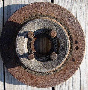
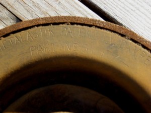
All XK 120/140/150 crankshaft dampers have been manufactured by Metalastik of Leicester, UK (since 1958 part of the Dunlop group). Most (all?) of the dampers have the following text stamped on the back (engine side) of the damper: METALASTIK PATENT T.V. DAMPER PART Nº 51/XXX whereby the last three numbers indicate the specific version. The abbreviation T.V. stands for “Torsional Vibration” damper.
Configuration of Metalastik dampers
The basic design of the Metalastik damper of the 51 series consists of a stamped dish of ⅛” steel (8” outer diameter, about 3½” inner diameter and a recess/depth of about ⅞”) to which a cast centre spigot for the damper-cone is riveted (12 rivets). The “floating weight” (or inertia disc) is bonded by thick rubber to the aforementioned steel dish. The material of the floating weight (9” outer diameter) varied over the years: cast iron, malleable cast iron and steel were used depending on the type of XK engine.
Two basic types used for XK’s
Metalastik manufactured three basic types for Jaguar (but also used by others like e.g. Austin Healey and Maserati). All crankshaft dampers with a cast iron or malleable cast iron weight (about ½” thick) were coded 51/177. The versions with a steel weight (⅜” thick) suitable for higher rev’s, were coded 51/211. Note that there was a third damper version coded 51/227, but these were only applied on 2.4 ltr engines and therefore never used on XK’s.
Over the years small changes have been made in particular related to the timing marks on the floating weight, but the Metalastik code number remained unaltered. Jaguar, however, changed the part number with every (minor) change, making it rather difficult to determine (more than 60 years later) what the corresponding Jaguar part number is for a particular Metalastik version.
1. Crankshaft dampers for Jaguar XK 120
1.1. Introduction engines 1948
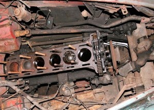
First photos and drawings presented during the introduction of the XK engine in 1948 show an engine without a damper fitted to the crankshaft.
 1948: without crankshaft damper

1.2. Jaguar part nº C2464 (Metalastik Part Nº 51/177)
From engine Nº W1001 (October 1949) to W8306 (May 1953) a Metalastik damper with a cast iron floating weight had been installed. The edge of the floating weight casting measures about 13.5 mm over 6.3 mm whereas the rest of the weight measures only 9.5 mm (see drawing with cross section of damper). Outer diameter of the floating weight is about 9” and the inner diameter 6¼”. There are no timing marks on the damper. This version was used until May ‘53.

 C2464 damper Cross section (October 1953)


 Part Nº 51/177


1.3. Jaguar part nº C5809 (Metalastik Part Nº 51/211)
June 1951 saw the publication of the famous Service Bulletin 95 which gave a survey of the “Tuning Modifications on XK 120 cars for Competition Purposes”. Next to a lightened flywheel a “Special Crankshaft Damper Part No. C5809” was introduced which was “specially tested for operation at high rpm”.
In comparison to Part Nº C2464 the floating weight was made of steel instead of cast iron, apparently better coping with the continuous higher revs at which these dampers were run (maximum engine output now at 5800 rpm instead of 5400 rpm). The floating weight in steel measures only ⅜” (or 9.5 mm) instead of 1/2″ (or 13 mm) of the cast iron version, which relates to the difference in specific gravity. This crankshaft damper used a special rubber mix for the bonding of the steel weight. The Metalastik Part Nº 51/211 had the mark “COMP” stamped at the front (see photo).
 “COMP” stamped at the front

Outer diameter of the steel floating weight measures about 9” and the inner diameter 6¼”. Total weight is about 3.3 kilos.
This damper was used on the following XK 120s:
1.3.1. Earlier and later engines modified for Competition purposes according SB95 replacing the C2464 damper
1.3.2. Engines in Special Equipment (SE) cars from June 1951
1.3.3. Engines Nº W8307 to W8380 (production month May 1953). Apparently the old damper C2464 was no longer available while the successor type C8020 still had to be manufactured. For these 73(?) standard engines damper C5809 was used.
 C5809 with crankshaft pulley installed

1.4. Jaguar part nº C8020 (Metalastik Part Nº 51/177)
From Engine Nº W8381 (May 1953) a new Metalastik damper with malleable cast iron floating weight was used. Metalastik changed from a (grey) cast iron to a malleable cast iron version because of its more ductile characteristics.
The floating weight is about 13 mm thick at the edge. Outer diameter measures about 9” and the inner diameter 6¼”. This damper has no timing marks (or lines) at the front side.
2. Crankshaft dampers Jaguar XK140
2.1. Jaguar part nº C8241 (Metalastik Part Nº 51/177)
Engines with a standard cylinder head received this damper. This part succeeds C8020 meaning a Metalastik damper with malleable cast iron floating weight. By September 1954 this damper received 3 timing marks at 0 – 5 – 10° BTDC without any figures stamped above the marks.
 C8241 (cleaned before painting)

2.2. Jaguar part nº C8129 (Metalastik Part Nº 51/211)
Used on engines with the C type cylinder head, this damper is similar to damper C5809 meaning the inertia disc was made of steel and used a special rubber mix for the bonding of the weight. As it was a 51/211 version it continued to show the “COMP” mark. It received 3 timing marks (lines) at 0 – 5 – 10° BTDC without any figures stamped above the lines.

 C8129
C8129


Note that the stamping on the rear side shows the marking METALASTIKPATENT T.V.DAMPERPARTNº51/211 without any spacing between the words. This in contradiction to the Metalastik 51/177 version where there are spaces between the words and the part number is given in a second line.


For Metalastik the basic design was unaltered and they continued with their part number 51/211. Jaguar, however, changed the part number to C8129 because of the new timing marks. The outer diameter of the damper is 9” or about 230 mm. This damper has a ⅜” or 9.5 mm thick floating steel weight with an inner diameter of about 160 mm. The overall weight of the damper is about 3.3 kilos of which the floating weight takes about 1.5 kilos, meaning 46% of the total weight is in the inertia disc.
3. Crankshaft dampers Jaguar XK150
3.1. Jaguar part nº C8241 (Metalastik Part Nº 51/177)
All 3.4 litre engines from March 1957 onwards continued using the damper of the standard XK 140 engine. See under 2.1. From May 1960 onwards the TDC timing mark was continued on the edge of all dampers to facilitate timing by means of “modern” testing equipment.
 TDC timing mark on edge from May ’60

3.2. Jaguar part nº C15274 (Metalastik Part Nº 51/211)
Late 1959 the 3.8 litre was introduced and received another updated version of the 51/211 crankshaft damper. Basic dimensions remained unchanged but the markings were new.

 C15274


The damper version now had a full timing scale with marks at 0 – 5 – 10° BTDC and the figures stamped above the lines. Smaller markings every degree between 0 and 10°. The TDC timing mark was continued on the edge of the damper. Dimensions remained identical to C8129 and it still carried the mark COMP.

 C15274


4. Later Crankshaft dampers Metalastik Part Nº 51/227
With the introduction of the 2.4 litre engines in 1955 the need arose to develop an optimised version for this (short stroke) engine. Note that Metalastik developed a third range of Crankshaft Dampers with Part Nº 51/277.
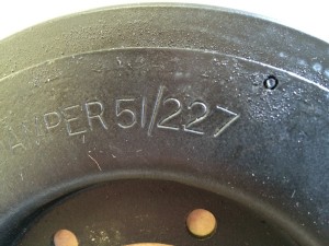 Example of the 51/227 series of dampers
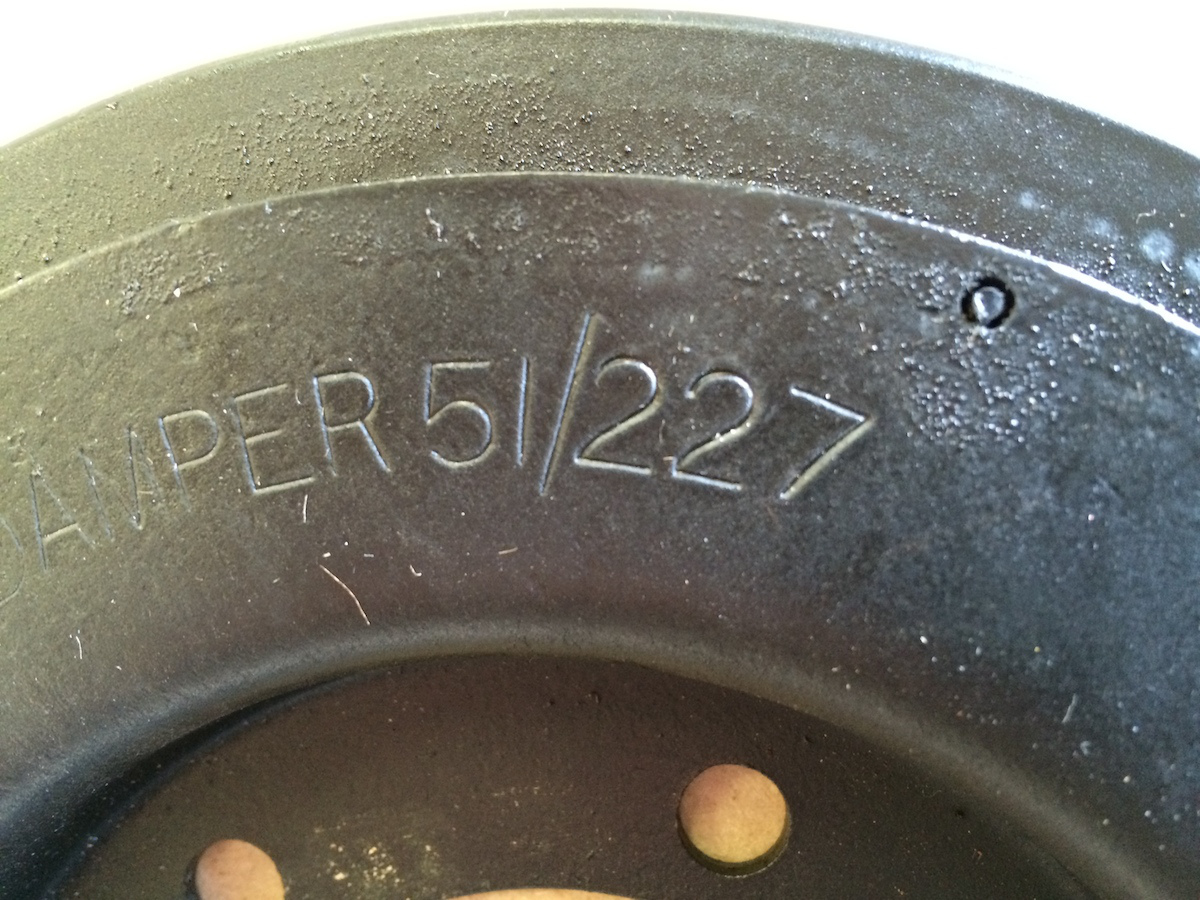
There were two 51/227 versions used by Jaguar:
- Jaguar Part No. C12037 mounted on 2.4 ltr. engines of the jaguar Mk 1 and Mk 2 (up to engine No. BJ6131) over the period 1955 up to 1963. These versions had one single timing mark (TDC) on the edge of the damper.
- Jaguar Part C24921 mounted on 2.4 ltr. engines of the Jaguar Mk 2 from engine No. BJ6132 onwards in the period 1964 till 1967. Here, however, the pulley and damper had been integrated.
Photo courtesy of Eric Kriss.
Overview of Ignition data for XKs
Note: all data in this overview are given in crank degrees and crank rpm.
The following information has been gathered from various sources (both Jaguar and Lucas), but the available information is at times unclear or confusing. Therefore the data should be regarded as “additional help” and not as the ”absolute truth”.
Jaguar used Lucas distributors for the engine of the XK 120, 140 and 150 (and of course for the Saloons of that era). For this overview to types of distributors are of interest:
- DVX(H)6A distributors for XK120 and XK140.
- DMBZ6A distributors for XK150.


Note the different lower aluminium housing of the DVX(H)6A (left) in comparison to the DMBZ6A distributor (right).
The difference between the distributors for the (early) XK 120 and 140 is mainly in the cap with horizontal spark plug cables for the XK 120 (up to 1953, recognisable in the letter H in DVXH6A) whereas later XK 120 and 140 distributors had vertical spark plug cables. A good example of that difference is the Lucas 40199 distributor which was used both in the XK 120 and 140: the XK 120 used the 40199A to D with type indication DVXH6A and the XK 140 had the 40199E with type indication DVX6A. The only real difference between the two being the distributor cap: 415708 for the XK 120 and 407043 for the XK 140. The XK 150 distributors of the DMBZ6A type are totally different from the DVX(H)6A types .
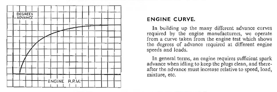
The surveys below also mention an E.C.M. curve which in fact describes the ignition advance from idle to maximum allowed r.p.m. as indicated by the manufacturer. There is a lot of discussion about the meaning of the term ECM as Lucas used in all of their ignition data.
In the Lucas “Overseas Technical Correspondence Course” Section 3 “Coil Ignition” Part 2 the following is explained:
Engine Curve: “In building up the many different advance curves required by the engine manufacturers, we operate from a curve taken from the engine test which shows the degrees of advance required at different engine speeds and loads.”
We may assume from this that Lucas was confronted with many different Engine Curve Models (ECM) and started to build up a “library of ECM’s” giving them specific numbers.
Ignition data for XK 120 engines

Ignition data for XK 140 engines

Ignition data for XK 150 engines

Original fan belt Jaguar XK
1. Introduction
The precise size and type of the fan belt for a particular Jaguar XK is often very hard to determine and the information given by many suppliers is confusing or at times even misleading. But if you use your existing belt as an example for a new one, it is most likely that the original fan belt on your engine has already been replaced (several times). So what was the original fan belt like?
To complicate the problem of finding the correct belt for the Jaguar XK even more, fan belts have been (and still partly are) developed and manufactured according different (inter)national standards. The most important ones are BS3790 (or an earlier version of that standard) in the UK, the “Standard for Light-duty or Fractional-horsepower V-belts” of the Rubber Manufacturers Association RMA in the USA and the German DIN 2215 standard for Classical V-belts. Today all V-belts are ISO standardized and practically all manufacturers in all countries adhere to these standards. But unfortunately this does not help as the original 1950s fan belt dimensions have been modified into “something close” but certainly not identical.
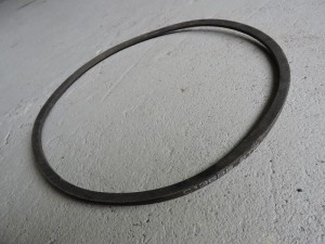
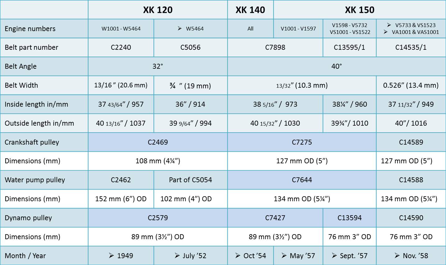
Early Jaguar XK 120s initially used a Dunlop ¾” (19 mm) wide 32° V-angle belt type. Around 1952 the length of the belt changed but otherwise remained identical. With the arrival of the XK 140 in 1954 the fan belt became narrower with a width of only 13/32” (10.3 mm) and an angle of 40°, which version was continued for the XK 150 until 1959 when a wider belt type was introduced with a width of 0.526” (13.4 mm) and 40° angle which changed later to ½” (12.7 mm) 40° belt for standardization reasons.
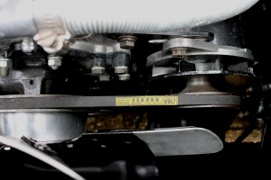 Original 1950s fan belt on XK 140

Belts with the original widths and 32° V-angle for the early 120s are no longer manufactured or supplied but belts with a 36° V-angle are still available and fit without problem. Wider V-angles like 40° as a replacement for the 32° V-angle belt are widely available but will have some effect on e.g. the correct length (so care is required when using these modern belts). “Notched” belts are a development that started in the late 50s and have been applied on the last version of XK 150s.
On XK engines the fan belt is driven by the crankshaft pulley and runs over the water-pump and generator (dynamo) pulley. The required size, type and length of a belt is determined by (amongst others) the width of the belt type and the individual diameters of the 3 pulleys. Any modification to one of the pulleys introduces the necessity to change the fan belt dimensions. The information given below tries to highlight these changes and to provide information on the required belt per XK type. Please keep in mind that (1) the recommended fan belt dimensions relate to the original situation and furthermore (2) differences in dimension are possible per standard, brand or manufacturer: therefore a ± 10 mm tolerance on the length indication should be kept in mind.
Factory assembled engines most likely had Dunlop fan belts as standard equipment. Note that fan belt dimensions given hereafter refer to Dunlop manufactured belts as much as possible. Other (contemporary) original fan belts, recommended by the manufacturer for this particular type of car, may deviate from these (Dunlop) dimensions: when available these dimensions have been included in the survey of alternative/replacement belts.
2. Jaguar XK 120 fan belts
2.1 Early Jaguar XK 120 engines from W1001 up to W5464 (July 1952) with crankshaft pulley C2469 (4¼“ or 108 mm outer diameter) used pulley C2246 (6“ or 152 mm outer diameter) on the (round hub) water pump with the cast 5 blade fan and a cast iron pulley C2579 on the C45PVS generator (3½ ” or 89 mm outer diameter). The fan belt was coded C2240.
|
Code |
Top width |
Belt height |
Angle |
Inner circumf. |
Outer circumf. |
|
C2240 |
3/4” (19 mm) |
½” (12.7 mm) |
32° |
37 1/2 ” (956 mm) |
40 3/4” (1036 mm) |
Replacement belts:
- An original belt can sometimes be found at auctions or auto-jumbles, but after 50 years of degradation the quality should be thoroughly checked. However, carefully stored fan belts might do the job for several thousands of miles (but always take a spare one with you). Examples of original belts:
- Dunlop D305 (see above)
- Ferodo V340 (W :13/16″ (20.6 mm); IC 37 43/64″ (957 mm); OC 40 13/16 (1037 mm)
- Raybestos R330
- John Bull V177
- B.F. Goodrich 38
- The Gates TR24400 Green Stripe Truck & Bus series (or equivalent from different brands) is a ¾” (19mm) wide belt with a 36° angle and an outside length of 40⅝” (1030 mm). As the belt-width (19 m) is slightly less than the original belt (20.6 mm) the somewhat shorter length (7 mm) will be compensated.
- If not the “next in size” belt Gates TR24403 with an outside length of 1040 mm might be an option.
- An interesting candidate with the correct width comes from a different source: the old German ‘Klassischer Keilriemen’ version according DIN 2215/ISO 4184. Although the 20 mm version will be (has been?) phased out, several 20 mm wide belts (with a 12.5 mm correct height) are still available on the market. Example: 20 x 950 Li with an inside length of 950 mm. According the DIN2215 standard the outside length is about 80 mm longer than the inside length meaning La = 1030 mm and the “effective” length Ld = 1000 mm. The V-angle is however 40°, but this belt may fit depending on the adjustability of the generator and the appearance comes very close to the original 13/16″ belt type.

Please note that the Jaguar Mk IV and Mark VII used a similar pulley, part number C1076, however with a 3¾” or 95 mm diameter. These larger pulleys may have been used as a replacement on XK 120 engines and will affect the required length of the fan belt. So check the part number of the pulley which is stamped in the casting between the vanes!
2.2 There is much confusion about the exact fan belt dimensions of the later Jaguar XK 120s from engine number W5465 (July 1952 till end of production). This engine still had the same crankshaft and generator pulley but the water-pump pulley had changed: this much smaller pulley (102 mm or 4” outer diameter) had been integrated with the water pump hub and the combination was coded C5054. There was a 4 bolt flange for the new 6 blade fabricated aluminium fan. The new shorter fan belt was coded C5056.
|
Code |
Top width |
Belt height |
Angle |
Inner circumf. |
Outer circumf. |
|
C5056 |
¾” (19 mm) |
½”(12.7 mm) |
32° |
36.66” (930 mm) |
39.41” ( 1001 mm) |

Replacement belts:
- Original belts can sometimes be found at auctions or auto-jumbles, but after 50 years of degradation the quality should be thoroughly checked. Examples:

-
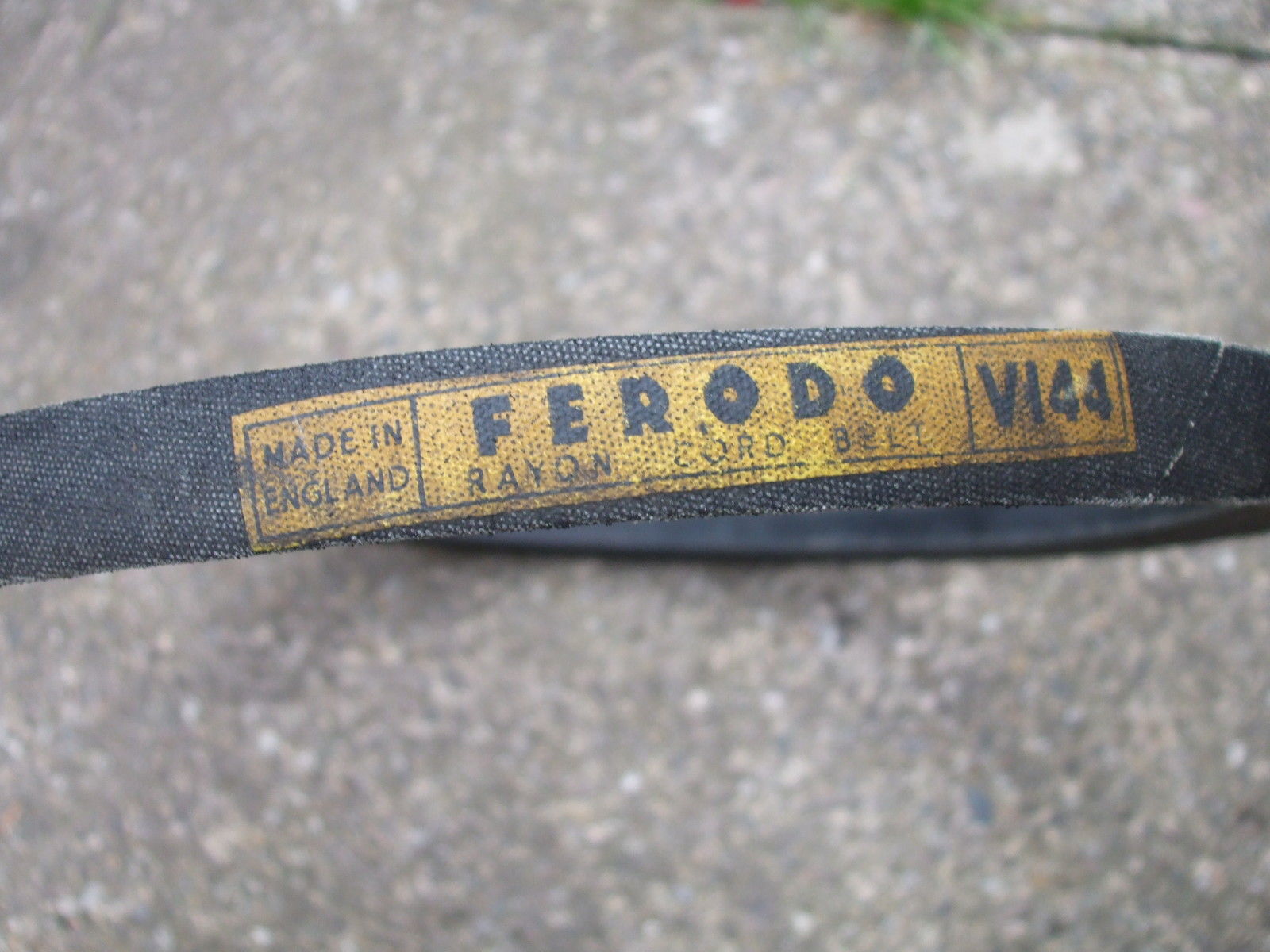
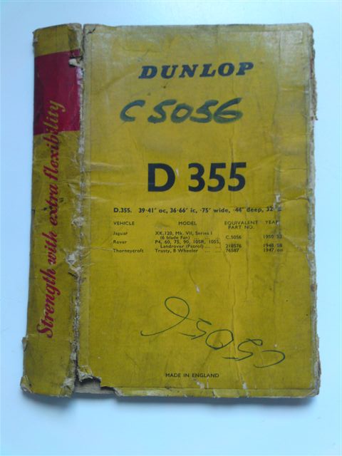
- Dunlop D355 see photo below
- Ferodo V144: (.75” W x .44 H x 39.41” OC x 36″ IC x 32°); see photos above
- Raybestos R265
- Mintex TK339 (unconfirmed)
- John Bull V516: (47/64” W x 15/32” H x 37 1/16” IC x 32°)
- Quinton Hazell DB322
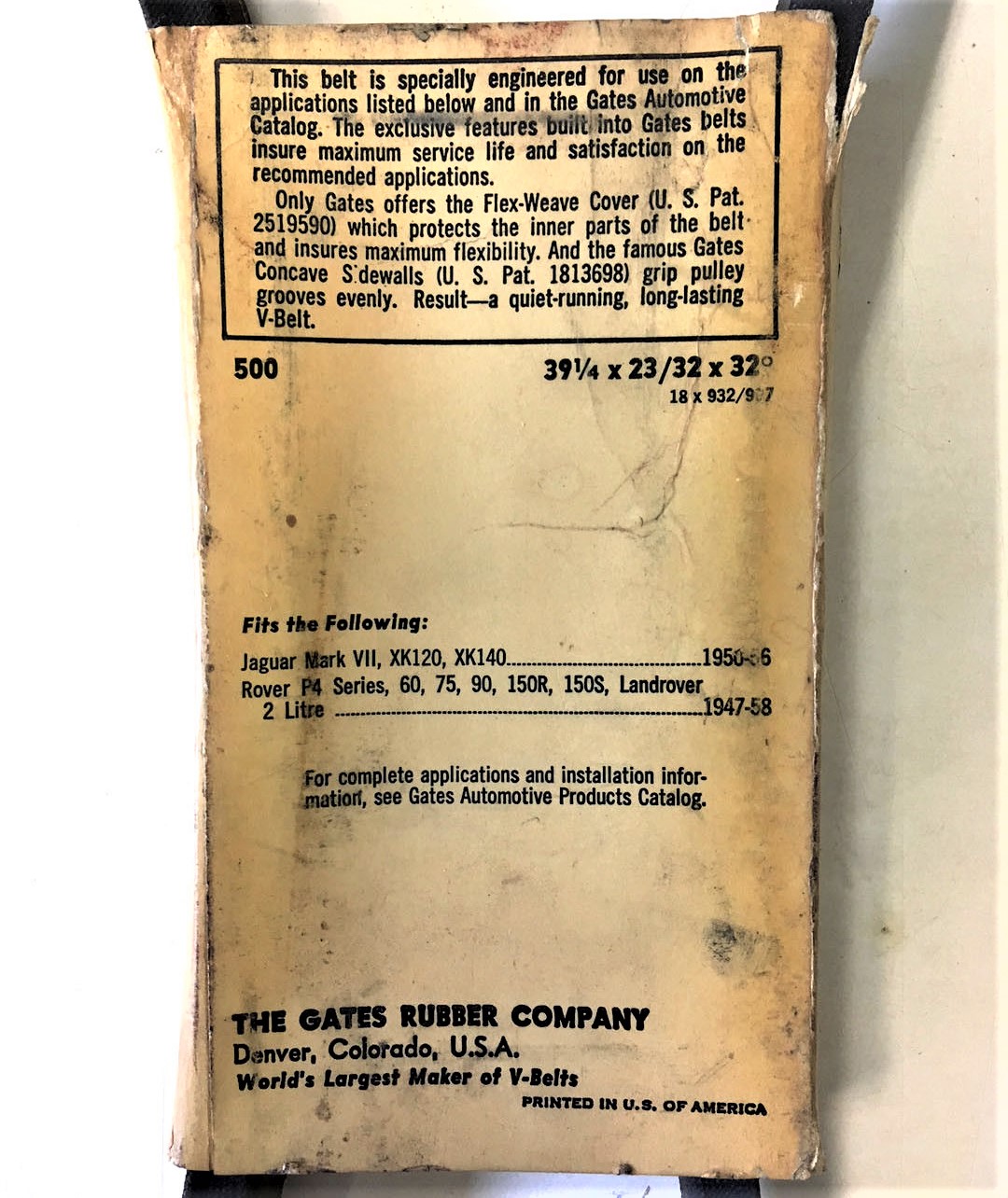
- Gates Vulco V-belt 500 (23/32″ W x 23/32″ H x 39¼ ” OC x 32°)
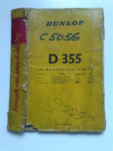
 Original Dunlop D 355 packaging Original Gates Vulco 500 fan belt
- Gates offered a 23/32″ (18.2 mm) fan belt, claiming this suited the Mk VII, XK 120 and XK 140 in the period 1950 – 1956. This survey is incorrect as this fan belt only suit some XK 120s and Mk VIIs with the C.5060 belt. The length of the Gates belt is 39¼ ” which is close to the Ferodo V144 with 39.41″.
- There seems to be no properly fitting ¾” (19 mm) Gates Green Stripe Truck & Bus series 36° belt, but Gates TR24379 might come close with an outside length of 38½” (980 mm) which is only 14 mm too short, provided the generator can be sufficient adjusted towards the block.
- We noticed that some Jaguar part suppliers provide the TR24400 also in this case, which however is with 57 mm by far too long and cannot be recommended.
- The B36 belt (from various suppliers like Gates Hi-Power® II) may fit because, although with a width of 21/31” (17 mm), it has the correct outside length of 39” or 990 mm. It will run deeper in the 32° V-groove which again is somewhat compensated by the wider V-angle of 36°.
2.3 There are sources mentioning that some very late XK120s (and Mk VIIs) may have been executed with an 8 blade fan and the pulleys of the XK140. The required fan belt is described in the following chapter.
3. Jaguar XK 140 fan belts
3.1 Jaguar had been experimenting with narrow belts on the XK 120 C-type to minimize power losses in the “auxiliary” engine parts. The width and angle of the belt changed therefore with the introduction of the XK 140: a 40° V-angle belt instead of the former 32° V-angle and a much narrower type of about 10 mm versus the much wider 19 to 20 mm of the XK 120. The crankshaft pulley had changed (now C7275) with a 5” or 127 mm OD, the water-pump pulley was new (C7644) with a 5¼” or 134 mm OD, as was the dynamo pulley (C7427) with a 3½” or 90 mm outer diameter. All XK 140s over the entire production run had the same fan belt which was coded C7898.
|
Code |
Top width |
Belt height |
Angle |
Inner circumf. |
Outer circumf. |
|
C7898 |
13/32”(10.3 mm) |
11/32”(8.7 mm) |
40° |
38 5/16” (973 mm) |
40 15/32”(1030 mm) |

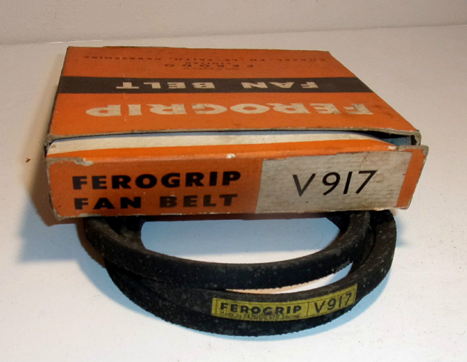
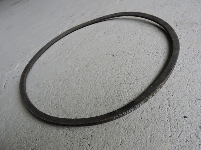
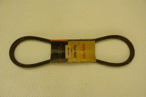
 Early (orange) branded FEROGRIP and later (red) FERODO box

Replacement belts:
- Original belts can sometimes be found at auctions or auto-jumbles, but thoroughly check their quality. Some examples:
- Ferodo V917 (dimensions see above)
- Raybestos R80 (dimensions as above)
- Quinton Hazell DB808
- Dunlop D333
- John Bull V529 (3/8” W x 5/16” H x 38 ¼ “ IC x 40°)
- B.F. Goodrich 1014
- Goodyear 1014 (13T412)
- The 36° angle Gates 7400 XL belt seems a good candidate with a width of ⅜” or 9.5 mm and an outside length of 40⅝” or 1030 mm. This belt is “notched” so not entirely original.

- Because these belts are actually somewhat wider than their code indicates and rise somewhat out of the groove, the Gates 7400 belt could turn-out to be too short. Gates recommends a Gates 7410 XL “notched”belt (also 36° angle) with an outside length of 41⅝”or 1055 mm as a replacement for Jaguar code C7898.
- A modern 40° angle generic belt type AVX10x1035 could also do the job and is available from various manufacturers, however this is “notched” belt.
- Another modern version is the SPZ1012 with an inside length of 974mm and an outside length 1025mm. This belt has the correct belt height of 8mm. If this fan belt is too short the next longer version SPZ1024 will fit with inside length 986 mm and outside length 1037 mm.
- The German Classic belt type 10 x 1000Li is another possibility although the height of this belt is only 6 mm (instead of 8 mm for the original version). Outside length is La = Li + 38 mm for this belt type, meaning outside length is 1038 mm (instead of the original 1030 mm).
4. Jaguar XK 150 fan belts
4.1 Early XK 150s (with engine number to V1597; about September 1957) continued to use the XK 140 fan belt C7898. Crankshaft pulley was still C7275 of the XK 140 engine, as was the water-pump pulley (C7644) and the dynamo pulley (C7427).
|
Code |
Top width |
Belt height |
Angle |
Inner circumf. |
Outer circumf. |
|
C7898 |
13/32”(10.3 mm) |
11/32”(8.7 mm) |
40° |
385/16” (973 mm) |
4015/32”(1030 mm) |
Replacement belts:
- See previous chapter on XK 140 fan belts.
4.2 The second belt type was used for XK 150 standard engines from number V1598 to V5732 and “SE” engine number VS1001 to VS1522. The somewhat shorter fan belt was now coded C13595/1. Jaguar had increased the speed of the dynamo by mounting a new pulley C13594 with a reduced diameter (from 3½ to 3” or about 76 mm). The crankshaft pulley remained C7275 and the water-pump pulley C7644. As these two pulleys remained unchanged, fan belt C13595/1 is still a 13/32” (10.3 mm) wide and 40° V-angle belt. Please note that some manufacturers make no difference between fan belt C7898 and C13595/1.
The Jaguar Mark 2 2.4 litre had a similar change involving a new pulley with reduced diameter (in order to increase the speed of the dynamo). The 2.4 litre pulley (Jaguar C.15592) , however, has a diameter of 3⅜” or 86 mm and should not be used because fan belt C.13595/1 will not fit.
|
Code |
Top width |
Belt height |
Angle |
Inner circumf. |
Outer circumf. |
|
C13595/1 |
13/32” (10.3 mm) |
11/32”(8.7 mm) |
40° |
38¼” (960 mm) |
39¾” (1010 mm) |
 Jaguar C15595
Replacement belts:
- An original belt can sometimes be found, but thoroughly check its quality. Examples are:
- Ferodo V904 (see above)
- Goodyear 476 (unconfirmed)
- Goodyear 1173 (13T391)
- Quinton Hazell DB800 (dimensions 1016 La x 9.5; also incorrect reference to XK 140)
- Dunlop D322
- The Gates 6275MC belt seems a good candidate with a width of ⅜”or 9.5 mm and an outside length of 39⅞” or 1013 mm.
- Mintex WFT400 is apparently identical to Gates 6275MC.
- Modern 40° V-angle types of belts are coded AVX10x1025 may fit, but are teethed or notched.
 Perfect Original QH fan belt DB800

4.3 The third belt type was introduced in November 1958 from 3.4 litre engine number V5733 and VS1523 and also used for all 3.8 litre engines from engine numbers VA1001 and VAS1001 onwards. A wider belt was introduced and this required all pulleys to be changed although their diameters remained the same and thus the outside length of the fan belt remained the same (1015 mm). This was in fact for the first time a “notched” type of fan belt on Jaguars (initially indicated by most suppliers with suffix N). The new water-pump pulley was coded C14588, the crankshaft pulley was now C14589 and finally the dynamo pulley C14590 (the fact that these parts have sequential code numbers may indicate that the Jaguar development department changed the complete belt system in one operation). Jaguar initially introduced a 0.526“ (13.4 mm) wide and 40° V-angle belt type coded C14535/1. However, some years later this belt type had been changed (or standardized?) to a ½” (12.7 mm) version with an inside length of 37.08” or 942 mm and an outside length of 39.78” or 1010 mm.
|
Code |
Top width |
Belt height |
Angle |
Inner circumf. |
Outer circumf. |
|
C14535/1 |
0.526“ (13.4mm) |
27/64” (10.7mm) |
40° |
3711/32” (949 mm) |
40” (1016 mm) |
Replacement belts:
An original belt can sometimes be found, but thoroughly check its quality. Examples:
- BMLC MOWOG 13H1840
- Ferodo V4895N (unconfirmed)
- Ferodo V6985N (see above)
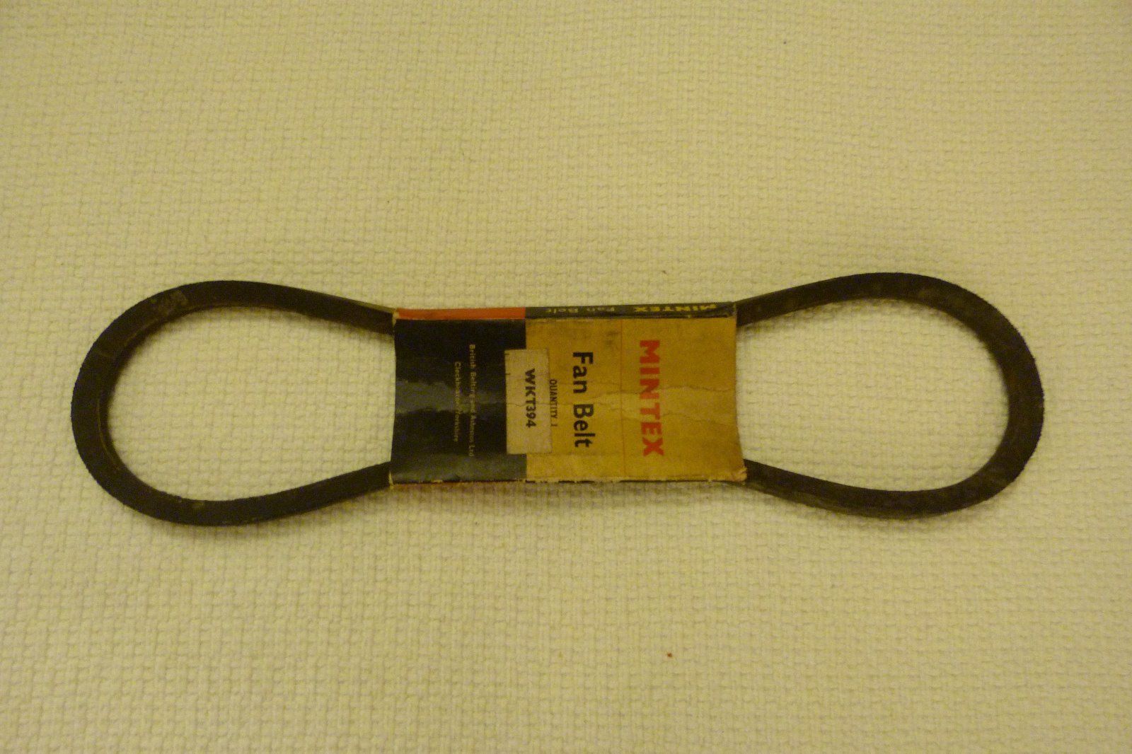
- Mintex WKT394 (slightly shorter: OC 39⅜ ” , IC 36¾”)
- Quinton Hazell DB2920N
- Raybestos R6000
- Goodyear 16 (18T401)
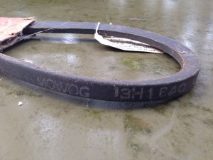 Original Mintex WKT394 Later BMLC MOWOG fan belt 13H1840

- Gates recommends the 36° angle Gates 9400 XL belt with an outside length of 40⅜” or 1025 mm. Again the extra length is because of the different width definition of this belt type and the fact that this belt “sticks out” of the groove.
- NAPA 25-9400 is related to the above however with a correct 17/32” width (13.5 mm) and a 40” outer length (1016 mm).
- Reference is made of the Goodyear 17401 which is a 0.53″ (12.7 mm) x 40″ (1016 mm) belt; this is a “notched” belt but is correct for the later type of XK150s.
- Modern 40° V-angle belts coded AVX13x1015 may fit depending on the adjustability of the generator.
5. Fan belt overview XK 120, 140 & 150
6. Overview of fan belt data for other early Jaguars from 1936 to 1960
During the “research” done in order to retrieve the original fan belts and their dimensions, a lot of additional information was found on other earlier Jaguar cars, that may help other Jaguar enthusiasts in their attempt to find a proper fan belt for their particular car. This information can be found in the table underneath.

Oil dipstick for XK engines
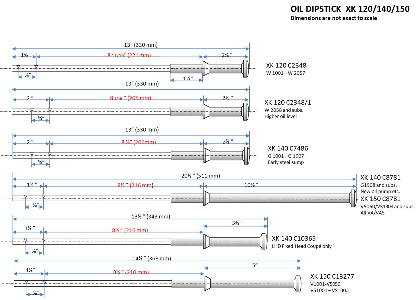
Various types of dipsticks (indicating the engine oil level in the sump) have been used over the period of 1948 to 1961 for the XK’s. Not only changed the shape and length of the dipstick but also the actual minimum and maximum oil level mark did not remain the same. There were in total 6 versions:
- The XK 120 started with dipstick C2348 from its introduction in 1948.
- The first change was made in January 1950 (C2348/1) caused by an increased oil quantity: oil level was increased by ⅝” (or 16 mm). It was also recommended to cut new marks in the C2348 dipstick of already supplied XK 120 engines.
- With the introduction of the XK 140 a new dipstick was used (C7486) which had a minor difference in oil level but was otherwise identical to the previous version.
- A new dipstick was supplied from engine number G1908 onwards (coded C8781) after an oil pump modification. The maximum oil level was lowered by 3/8”( or 10 mm). This version had a much longer handle and it was continued over the rest of the production of XK 140 (except LHD FHC: see under 5) and the later 3.4 and 3.8 XK 150s (see early exceptions under 6).
- The XK 140 in LHD FHC execution had a special dipstick coded C10365 with a much shorter handle. This was because of the restricted space of the FHC body version in general and the LHD steering column in the way more in particular.
- Early 3.4 (V 1001 – V5059) and 3.4S engines (VS 1001 to VS 1303) had a different dipstick coded C13277. The maximum oil level had been slightly raised (about 1/4 “or 6 mm) and the handle was shorter in comparison to the later C8781 version.
Thermostats for Jaguar XK 120, 140 and 150
Original Jaguar XK 120, 140 and 150 thermostats.
Jaguar applied a “Bellows”-type of thermostat with moving sleeve for all of their early XK engines. Jaguar initially used two different thermostat types, provided by either Smiths or British Thermostat where the latter type was stopped fairly soon after production of XK engines had started (see below). It remains unclear whether Smiths actually manufactured these products themselves or that they were purchased from Quinton-Brivec of Colwyn Bay (North-Wales): the construction of the two brands looks very similar. AC of Dunstable (UK) was another manufacturer of thermostats, but with a clearly different construction.
The “British Thermostat” version was only fitted to Mark VII engines (numbers A2001 to A6000) and this thermostat is non-interchangeable with the Smiths version. The British Thermostat Company (also known as Teddington) manufactured all sorts of thermal control equipment, mainly based on the use of seamless metallic bellows. From 1934 onwards they also manufactured car thermostats in their factories at Windmill Road, Sunbury-on-Thames, Middlesex. Brtish Thermostats was the largest manufacturer of seamless metallic bellows in Europe and must have supplied many other manufacturers of these bellows type of thermostats.
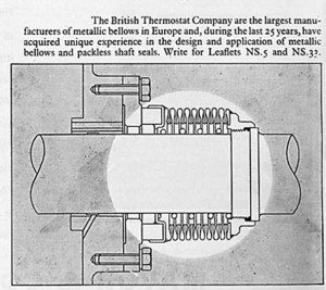
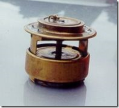
 British Thermostat Co. was a large supplier of bellows British Thermostat version was dome-shaped

The American Weston Miller Fulton (August 3, 1871 – May 16, 1946) is considered as the inventor of the bellows thermostat. The invention dates from the beginning of the 20th century, intended for use in heating systems. Around 1920 they were used to control radiator shutters in automobiles and in the Thirties as a thermostat for coolant in automobiles.
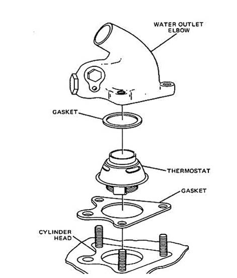
This type of thermostat has a bellows made from e.g. berylium copper or bronze and has been filled with (liquid) alcohol or volatile oil. The set point temperature of the thermostat is determined by the boiling point of the used liquid in the bellows. The Bellows-type of thermostat relies therefor on expanding gases within the bellows when the temperature of the cooling fluid rises. The moving sleeve around the outside of the lower portion of the thermostat blocks off the bypass port in the inlet manifold to optimize the flow of coolant through the engine, once the engine has warmed up and the thermostat has fully opened. It will be clear that other types of thermostat without a moving sleeve will negatively affect the warming-up periode of the engine.
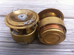
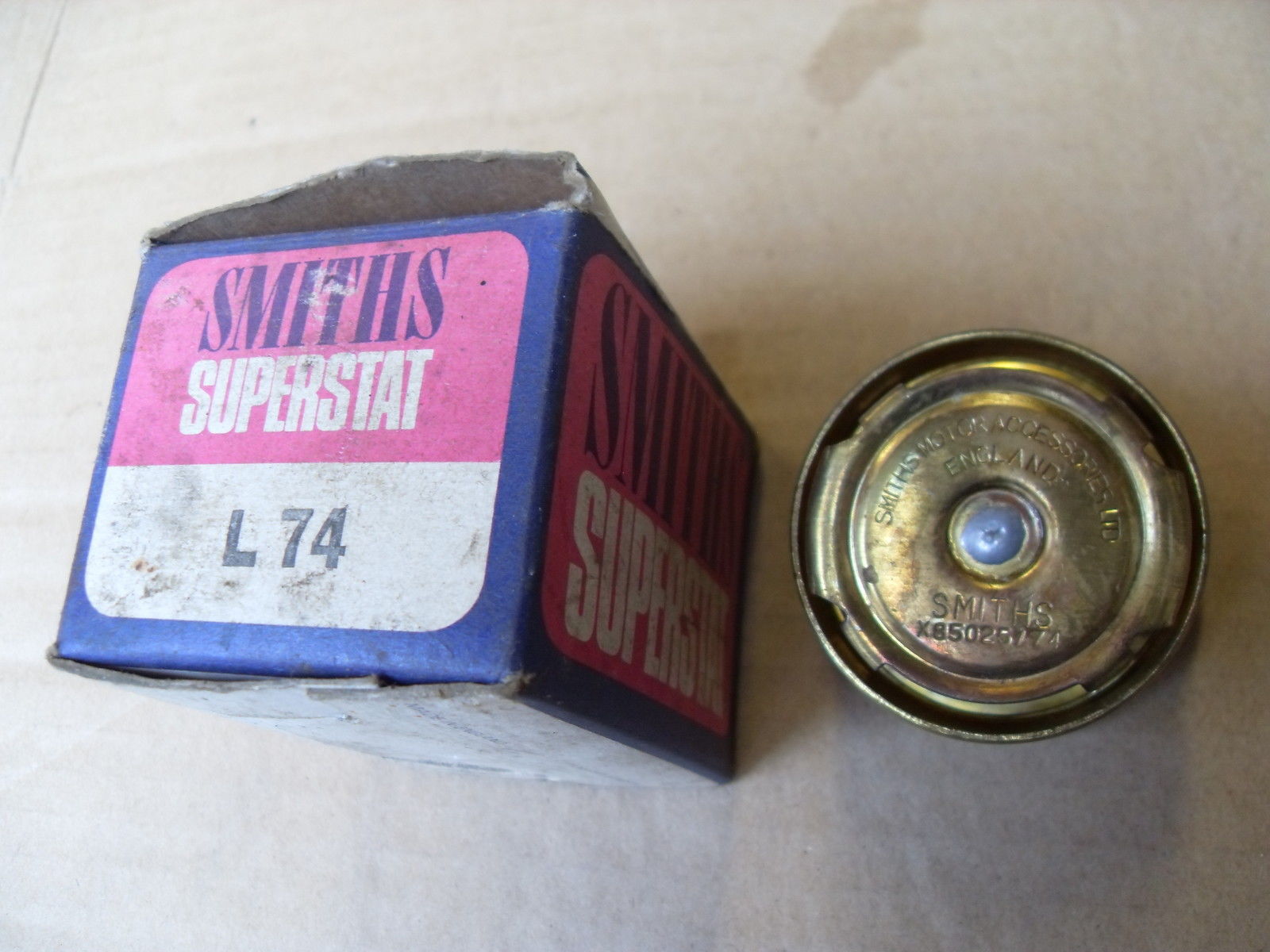
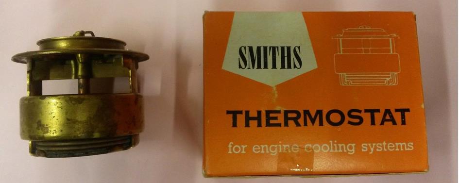
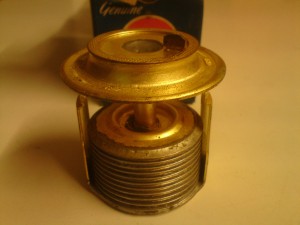
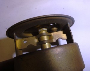 Original Smiths bellows-type thermostat Detail of “valve stem guide”


Bellows thermostats were first introduced in 1937 or 1938. A so called “bi-metal coiled system” (also supplied by Smiths) was applied before the introduction of Bellows thermostats. Smiths bellows-type thermostat types were used on many cars throughout the 1940s and 1950s: BMC, Ford, and many others used them for their engines with by-pass cooling system. Bellows thermostat production ceased in 1960 or 1961. The more typical wax pellet type thermostats were substituted.
Smiths bellows type thermostat on XK 120, XK 140 and XK 150.
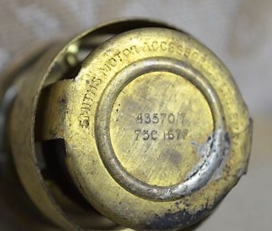
Smiths initially offered three ranges of Bellows-type thermostat: the 43570 series, 43605 series and 43655 series. They all commenced opening at a certain temperature (indicated on the thermostat) and had fully opened about 15 to 20°C higher than the opening temperature. The maximum valve lift is about ⅜” (or 9,5 mm).
XK 120
The XK 120 without a heater used Jaguar code C.3731 which is a Smith’s thermostat bellows type, part number X.43655 with an opening temperature of 60 to 63°C and has fully opened at 80°C. The XK 120s provided with a heater used thermostat Jaguar code C.3731/1 or Smiths X.43570/5 with an opening temperature of 73°C (163° F). Smiths X.43570/28 seems to be identical to X.43570/5 but is probably a later version. The XK 120 thermostat is placed in the inlet of the radiator. The outer diameter of the thermostat is 54 mm (2⅛ inch). The sleeve measures 48mm in diameter and 15mm in depth.

 Smiths X.43570/7 starts opening at 75 °C (167 °F) Smiths thermostat X.43570/28 opens at 73 °C (163° F)
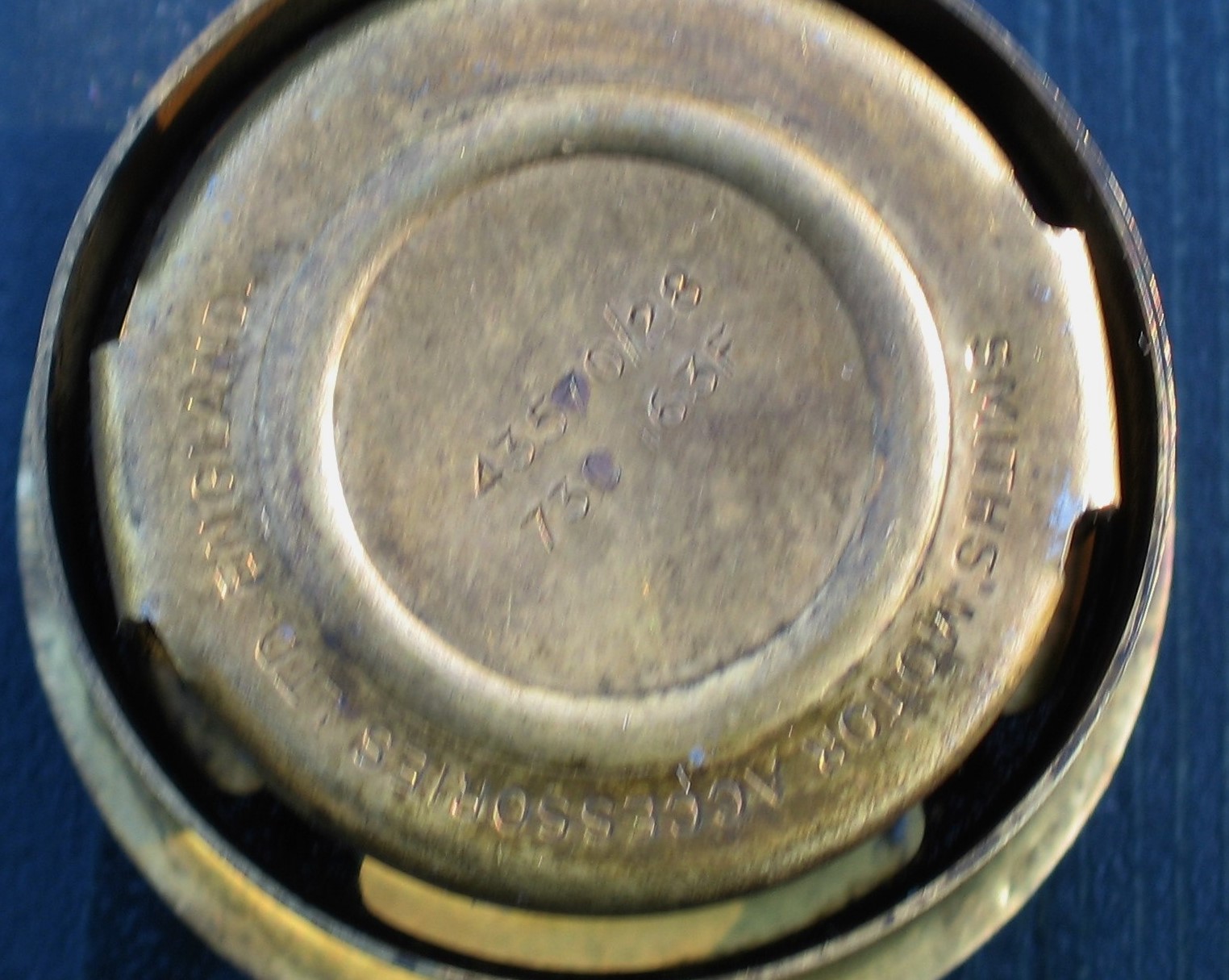
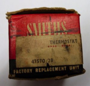
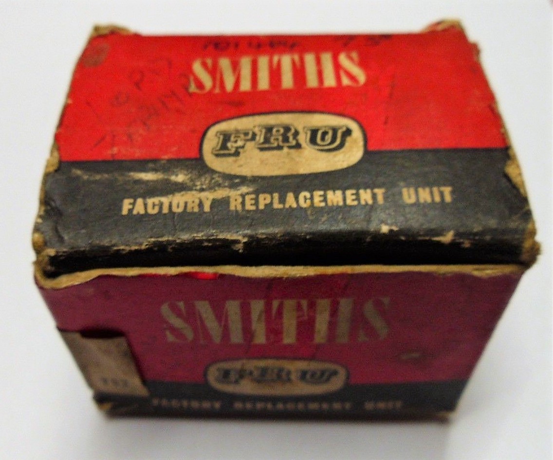
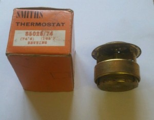
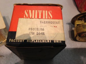
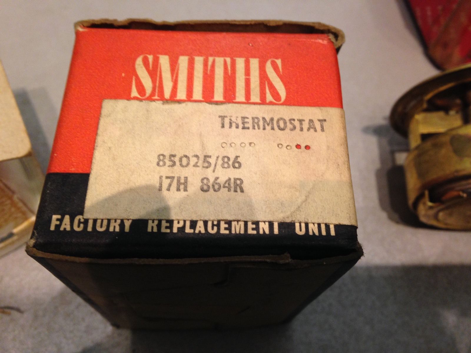
 Smiths X.43570/28 with 73°C (163° F) opening temperature as “Factory Replacement Unit” (FRU)

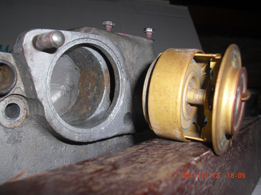
XK140
For the XK 140 engines, the thermostat was moved to the water outlet of the cylinder head. In March 1955 (engine number G2841) Jaguar announced that a new thermostat was fitted coded C.3731/1 (Smiths X.43570/5) but this version was already applied on the XK 120’s with a heater. Also reference X.43570/28 is used by Jaguar for C.3731/1; this version has an opening temperature of about 73°C (163° F). This old thermostat Smiths 43570 thermostat with an opening temperature of 60°C was no longer used. An alternative (winter) version carried Jaguar code C.7105 (Smiths X.43605/3) with an opening temperature of 83 (181° F).
XK150
The XK 150 range had yet another Smiths bellows-type thermostat with Jaguar code C.12867 having an identical opening temperature of 73° C (163° F) or C.12867/1 with an opening temperature of 80° C (176° F) for extreme winter climates. The corresponding Smiths numbers are not exactly known. Jaguar C.12867 for the Jaguar Mk 2 versions refers to Thermostat 02-0013 (which is an unknown brand code) and has an opening temperature of 70 to 75° C.
Change of part numbers and a (slightly) larger thermostat diameter
The Smiths coding system changed in early 1958 whereby the X.43xxx numbers were replaced by X.85xxx numbers, some with and others without the X prefix. Jaguar Service Bulletin No. 235 of January 1958 informs dealers that a new thermostat version has been introduced that has an increased outer diameter. Although this increase of .010″ or 0.25 mm is rather small, Jaguar changed the “Water Outlet Pipe” (or thermostat housing) for (all?) XK engines as there was “a possibility of the movement of the thermostat being restricted by the smaller bore water outlet pipe“. Note that SB 235 contained an error (wrong Smiths number quoted for old and new version) that has been corrected in SB 239 of February 1958 (although it contained a new typing error: X.85024/74 instead of X.85025/74).
It is therefore possible that the later Smiths thermostats with part number (X.)85025/xx may touch the walls of the older water outlet pipes. However, if you thoroughly clean the old water outlet pipes with sandpaper you will remove easily .010″ or 0.25 mm. Using older thermostats (X.43570/xx) in later pipes remains always possible.
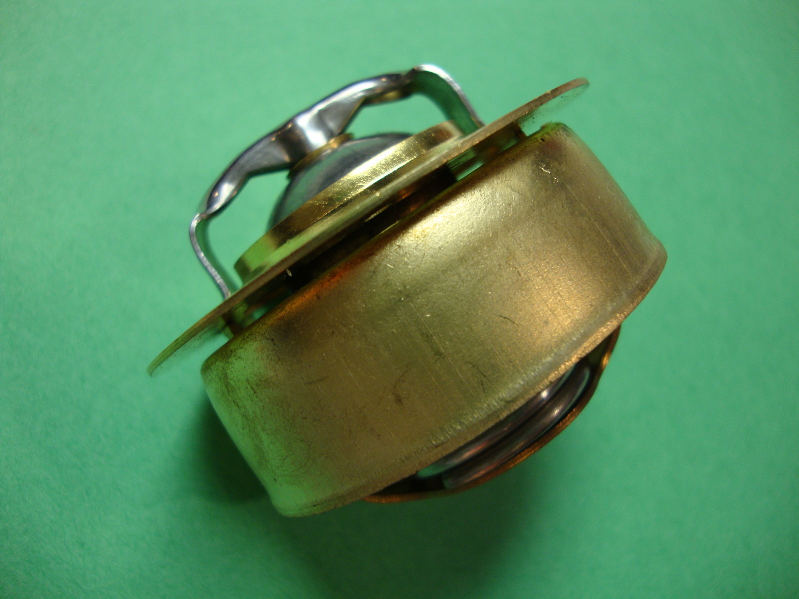
Apart from the diameter, also the overall height of the later Smiths thermostats changed. The early X.43570 thermostats measured about 2 inch (51 mm) whereas the later Smiths thermostats with code X.85025 measured about 1 13/16 inch (46 mm). The screen (blocking the by-pass) still moved to the correct position. This implies that the later Smiths thermostat used a different bellows system that would expand over a shorter distance given the same temperature rise. Note that AC manufactured bellows thermostats show a certain (constructional) resemblance with the later Smiths versions, having an overall height of about 1¾ inch (44 mm).
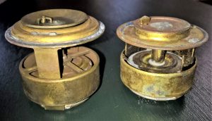 Smiths X.45370 (left) is taller than X.85025 (right).

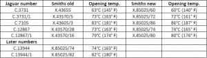
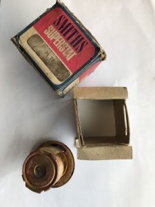
Smiths thermostats initially had green boxes with “Motor Accessories” pinted on the sides. Later Smiths made a dedicated blue & purple box for their thermostats using the name Smiths “Superstat” printed on the box: thermostats packed in these boxes still have the X prefix for the 85025 number. Around 1960 a new orange packaging was introduced.
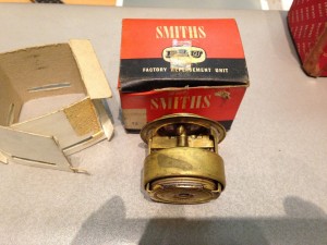
We also observed Smiths thermostats in a FRU packaging in red & black. These “Factory Replacement Units” also have sometimes the BMC code printed on the box label.
Note: the term “Superstat” is only used for a short period by Smiths. Stant (USA) still use the term “Superstat” for their thermostats.
Note: there were more Smiths thermostat-temperature versions available than the ones Jaguar had chosen. They are sometimes close to the nominal value Jaguar opted for. Examples: 85025/70 instead of 85025/74.
Survey of Smiths old and replacement part numbers:
 Smiths bellows type of thermostat survey.

 Smiths part X.85025/70 in original green box
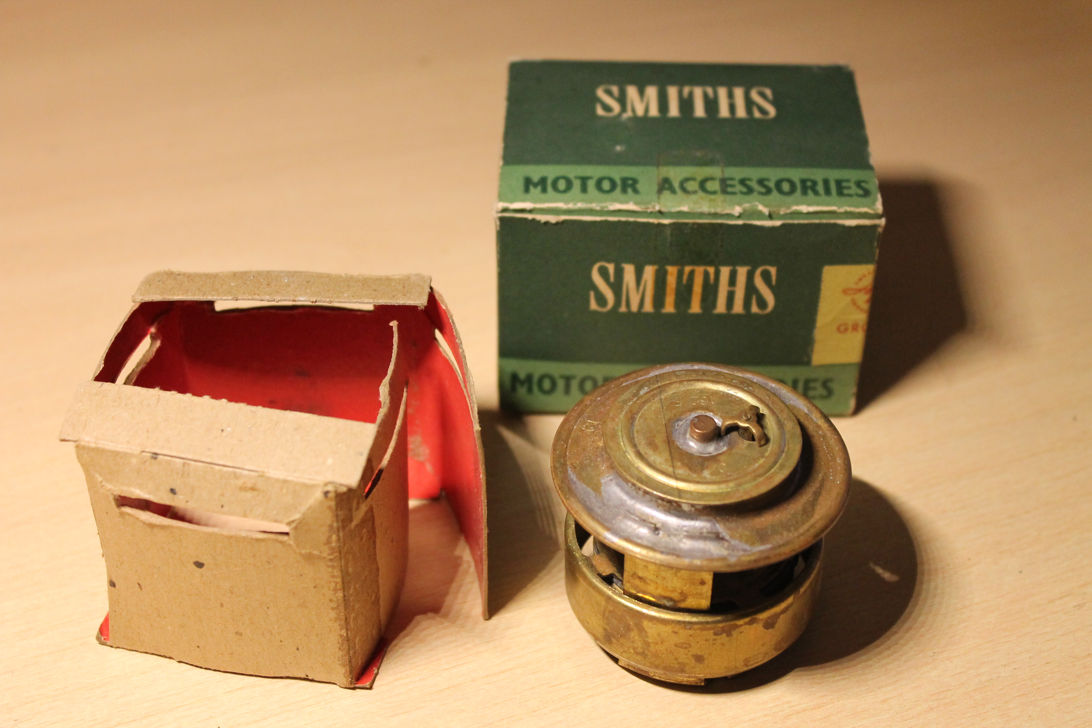
 Smiths X.85025/74 in “Smiths Superstat” box
 Smiths part X. 85025/70 in later orange box

 Smiths 85025/74 in orange box

 Smiths part X.85025/86 in orange box
 Later Smiths Factory Replacement Unit (FRU) packaging with 85025/86 winter thermostat

Other brands with replacement thermostats for XK engines
Original Smiths’ bellows type thermostats are difficult to find these days. After Smiths ceased production of this type of thermostat, the following brands became (and occasionally still are) available:
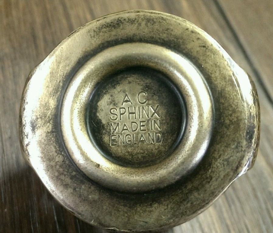
1. AC-Sphinx and AC (DELCO)
2. Lucas (Motostock) (made by AC Delco)
3. Quinton Brivec / Quinton Hazell (made by Quinton Brivec)
4. Remax (made by Quinton Brivec)
5.GH thermostats (made by Quinton Brivec?)
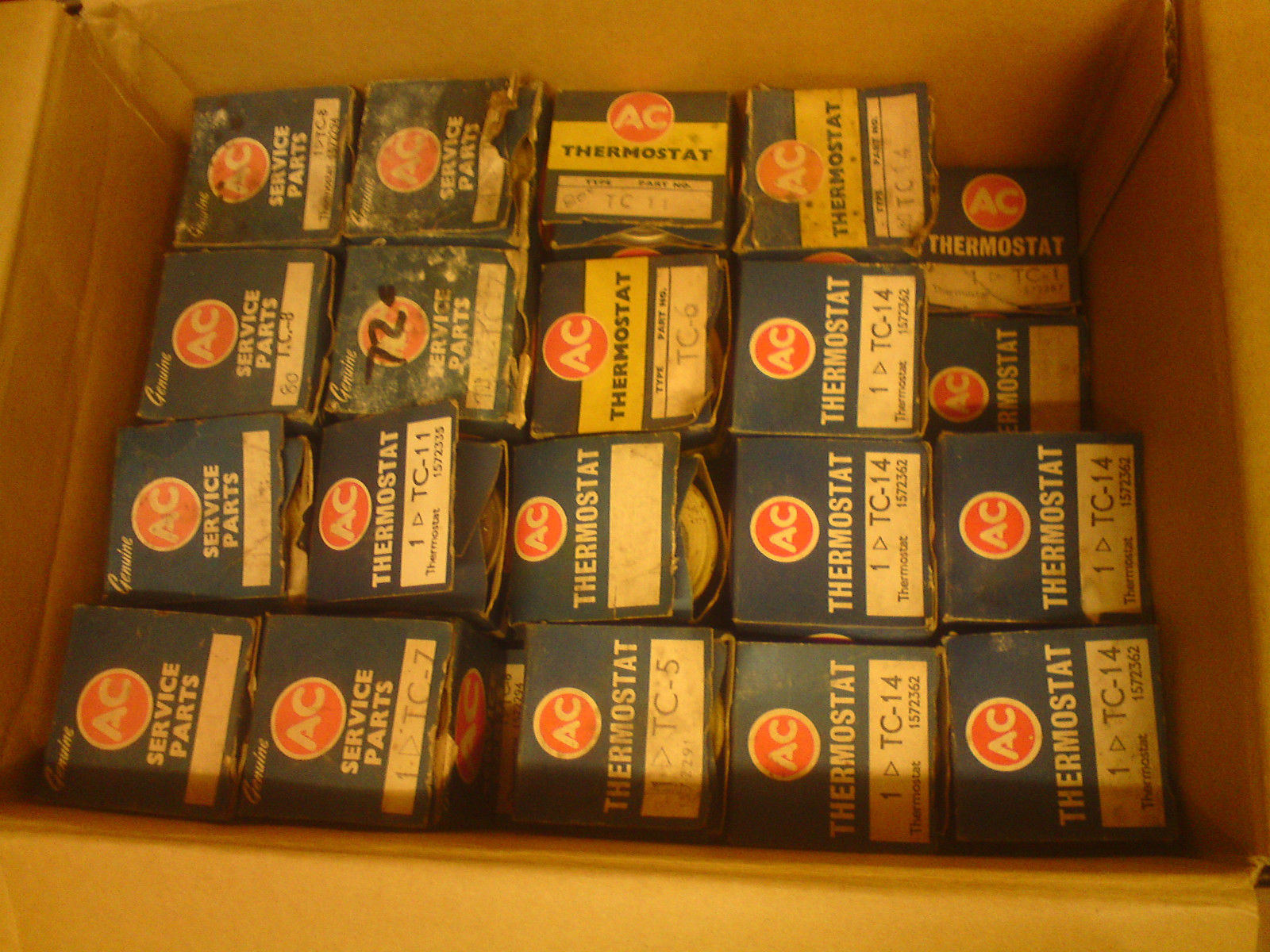
Survey of AC branded bellows type thermostat with screen
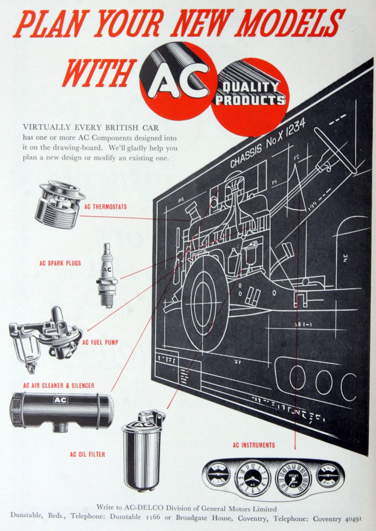
In 1952 AC Sphinx Spark Plug Co in Dunstable changed its name to AC-Delco, becoming a Division of General Motors Ltd. The Dunstable plant closed in early 2003, by then occupied by Trico Products. Also manufacturing facilities in Southampton. Main Office AC Delco at Stag Lane, Kingsbury, London NW9 OEH. The AC Delco company delivered a.o. thermostats to many UK car manufacturers beside Jaguar. See also the adds below dating from 1954 and a pre-1952 bellows thermostat still branded AC-Sphinx .
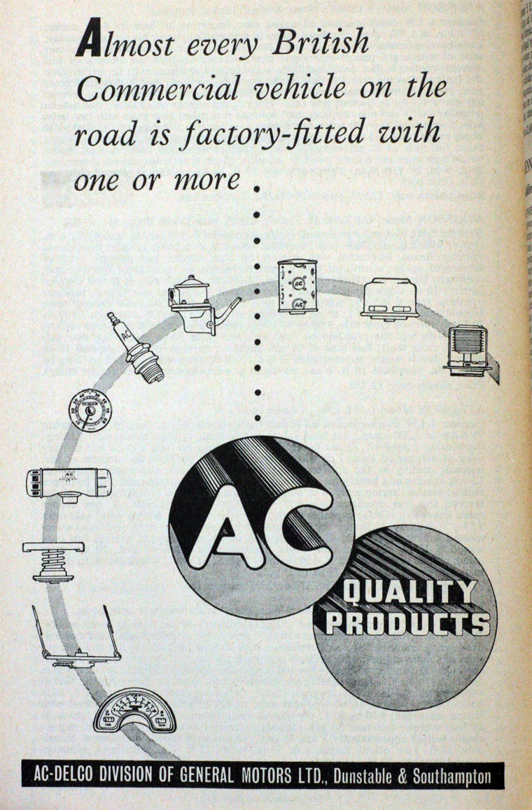
After WW2 AC Sphinx supplied two ranges of “bellow-type” thermostats: TC series without sleeve and the TF series with sleeve or as AC called it in a 1948 advertisment: “the by-pass type of thermostat“
 AC Sphinx adverisement of Aug 1948

Four different TF versions were manufactured and each one had an internal manufacturing code (next to the commercail code and the temperature stamped on the top). These numbers can be used as an additional check.
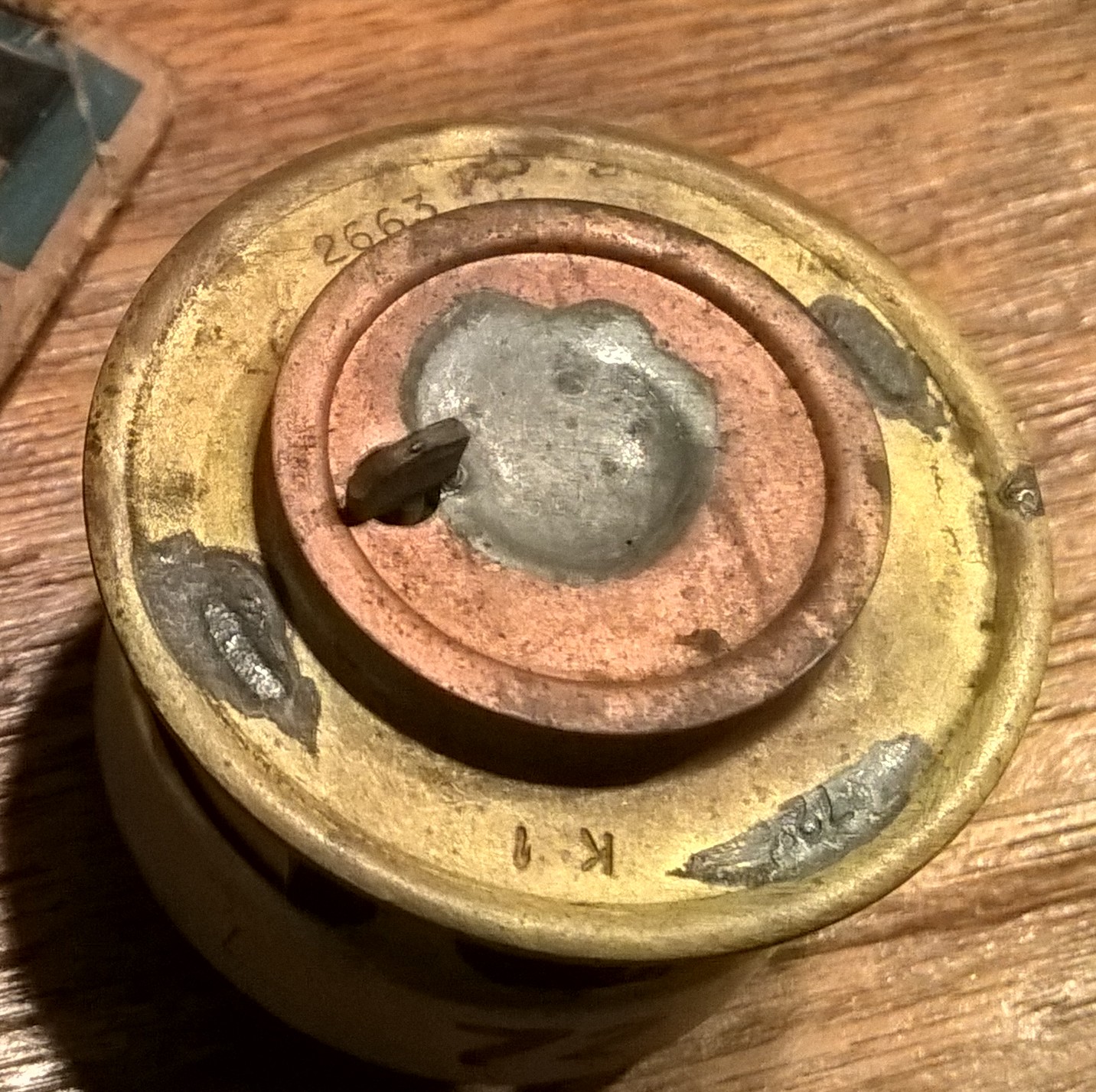
- TF-1 72° C 2235, 2663
- TF-2 80° C 2233, 2664 and later 2310
- TF-3 68° C 2202
- TF-4 86° C later 2307
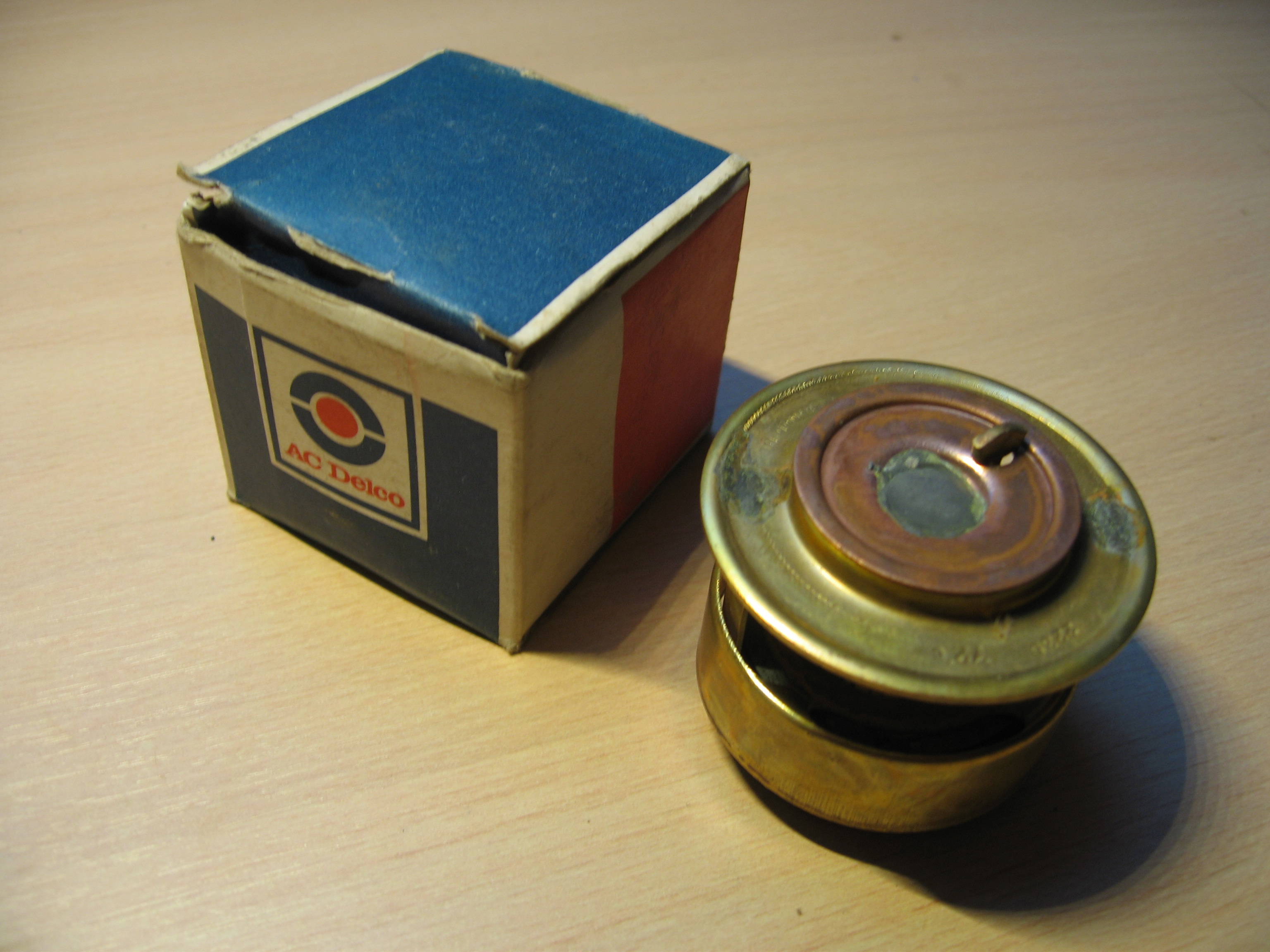
Different types of AC packaging are known: four are shown in this overview. We assume that the oldest packaging is printed in blue and yellow with the AC logo in red (see TF-4). Then there is a packaging without the yellow accent (see TF-1 LH photo), followed by white and blue packaging still AC branded (see TF-2 RH photo). The fourth type has AC Delco printed on the box (see TF-1 RH photo).
AC (DELCO) No TF-1 thermostat (replacing Jaguar code C3731/1 which had an opening temperature of 70° C). Opening temperature: 72° C (158° F) summer thermostat.

 AC TF-1
AC (DELCO) TF-2 thermostat (intermediate solution between Jaguar code C3731/1 and Jaguar code C7105). Opening temperature: 80° C (176° F) winter thermostat with manufacturing code 2310. TF-2 thermostats were available in a box or packed in a blister.
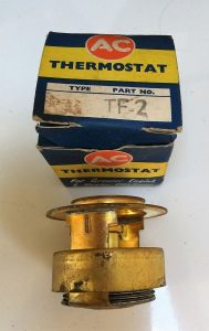
 TF-2
TF-2

AC (DELCO) No TF-3 thermostat with opening temperature 68° C (155° F) for “hot climate” conditions

AC (DELCO) TF-4 thermostat (replacing Jaguar code C7105 with opening temperature at 83° C). Opening temperature: 86° C (186° F) as winter thermostat.


The RH photo is interesting as it shows a TF4 stamped thermostat with a 68° C temperature which should have been 86° C !! The production code 2307 is however correct for a TF4 version. After checking it turned out to be a correct TF4 thermostat as it started to open at about 84° C. Probably this whole production batch had this error, so you have been warned…
Survey of Lucas (Motostock) (made by AC Delco)
In the 1980s the automotive activities of Smiths had been sold to Lucas and later to a group of factory employees. This probably explaines that Lucas started selling Smiths thermostats, although they were most likely made by AC Delco of Dunstable (UK).
Lucas LF1
Has an opening temperature of 72° C (160 F) and has the correct screen around the bellows
 Lucas LF1 in early packaging type
Lucas LF2
This version has an opening temperature of 80° C (176 F) as winter thermostat. This version has the correct screen around the bellows.
 Lucas LF2 in later packaging type

Survey of Quinton Hazell and/or Quinton Brivec

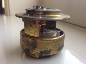
 Examples of Quinton-Brivec thermostat and typical box design with Welsh Dragon
Initially marketed under the Quinton Brivec brand ( located in Colwyn Bay, Wales and a divison of Quinton Hazell); see photos above. These thermostats had a special Quinton Brivec packaging showing the Welsh Dragon. Later the company brought the packaging under the Quinton Hazell brand (with a smaller Dragon). The code numbers are (more or less) identical for early and later packaging versions.
Quinton Hazell QT 100/200 series
Type QT 100/70, QT 100/72 and QT 100/74
These are bellows-type thermostats (including sleeve) with an opening temperature of 70°, 72° and 74° C respectively.
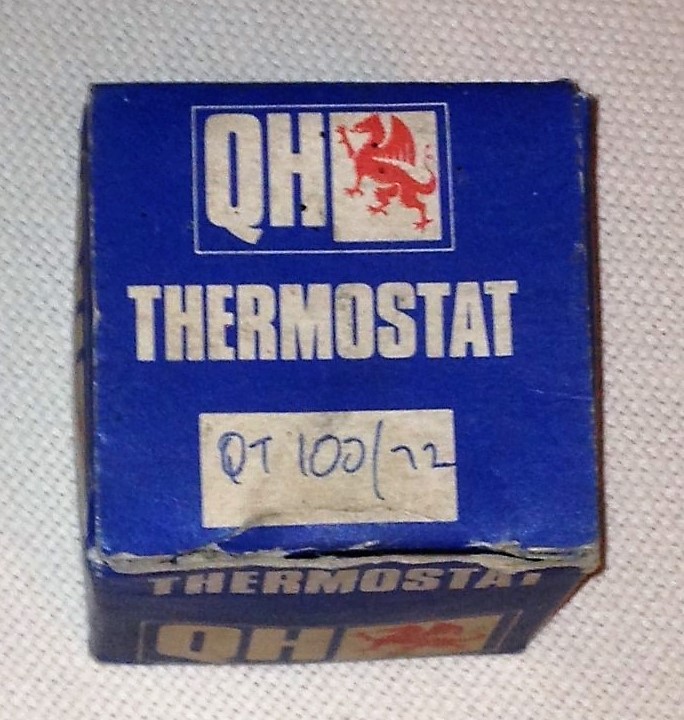
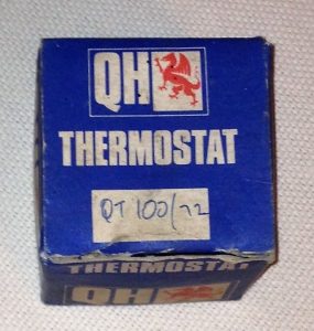 QT 100/72 in original Quinton Hazell box
Type QT 200/80 and QT 200/86
Opening temperature: 80 C (176 F) and 86 C (187 F) winter thermostat. With the correct sleeve.
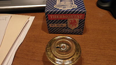
 Type QT 200/80 or WT 200/80 (for “winter” thermostat?)

Survey of Remax thermostats
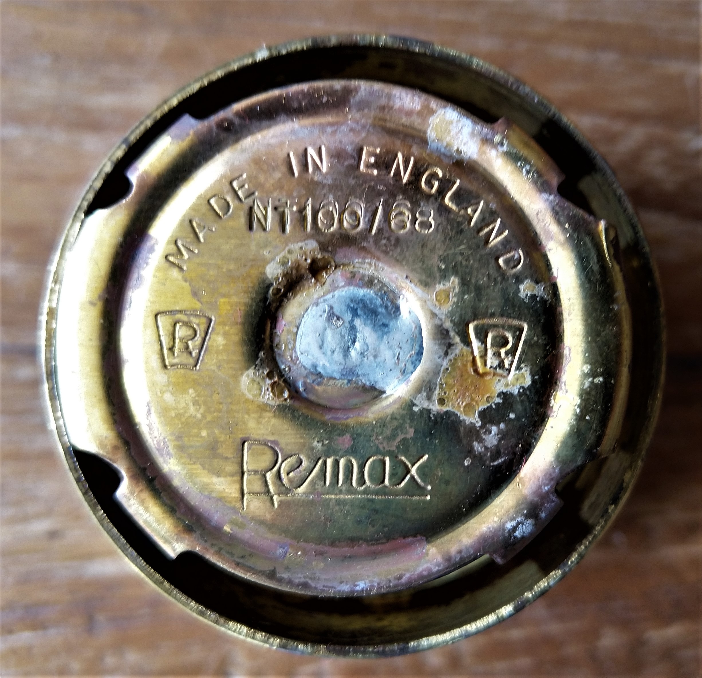
Remax of London had been established in 1928, manufacturing and supplying mechanical (precision) replacement parts for automobiles. After WW2 the company added Automobile Electrical Companents to their portfolio. Thermostats must have been a later addition to the sales programme, probably from the late 1960s onwards.
There is a strong resemblance between the Quinton Hazell and the Remax thermostats, which may lead to the conclusion that QH (or better Quinton Brivec) was their thermostat supplier. Even the type coding was almost identical: where QH refers to QT100 thermostats, Remax opted for NT100.
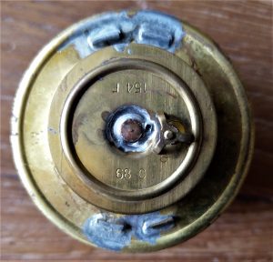
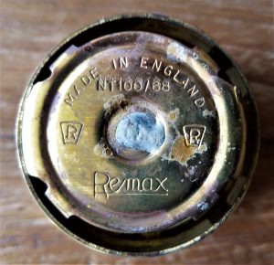 Remax NT100/68 thermostat has an opening temperature of 68 C.


GH thermostats (most likely made by Quinton Brivec)
Another UK brand named GH has been reported with bellows thermostats that have a large ressemblance with the afore mentioned thernostats as made by Quinton Brivec. There is very little information about the GH company.
The photos below show their type A70 with a 156 F or 70 C opening temperature. Also note their dedicated packaging branded GH.
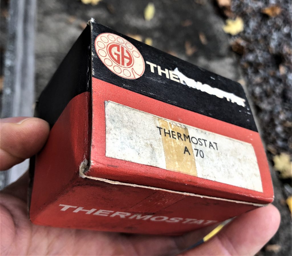
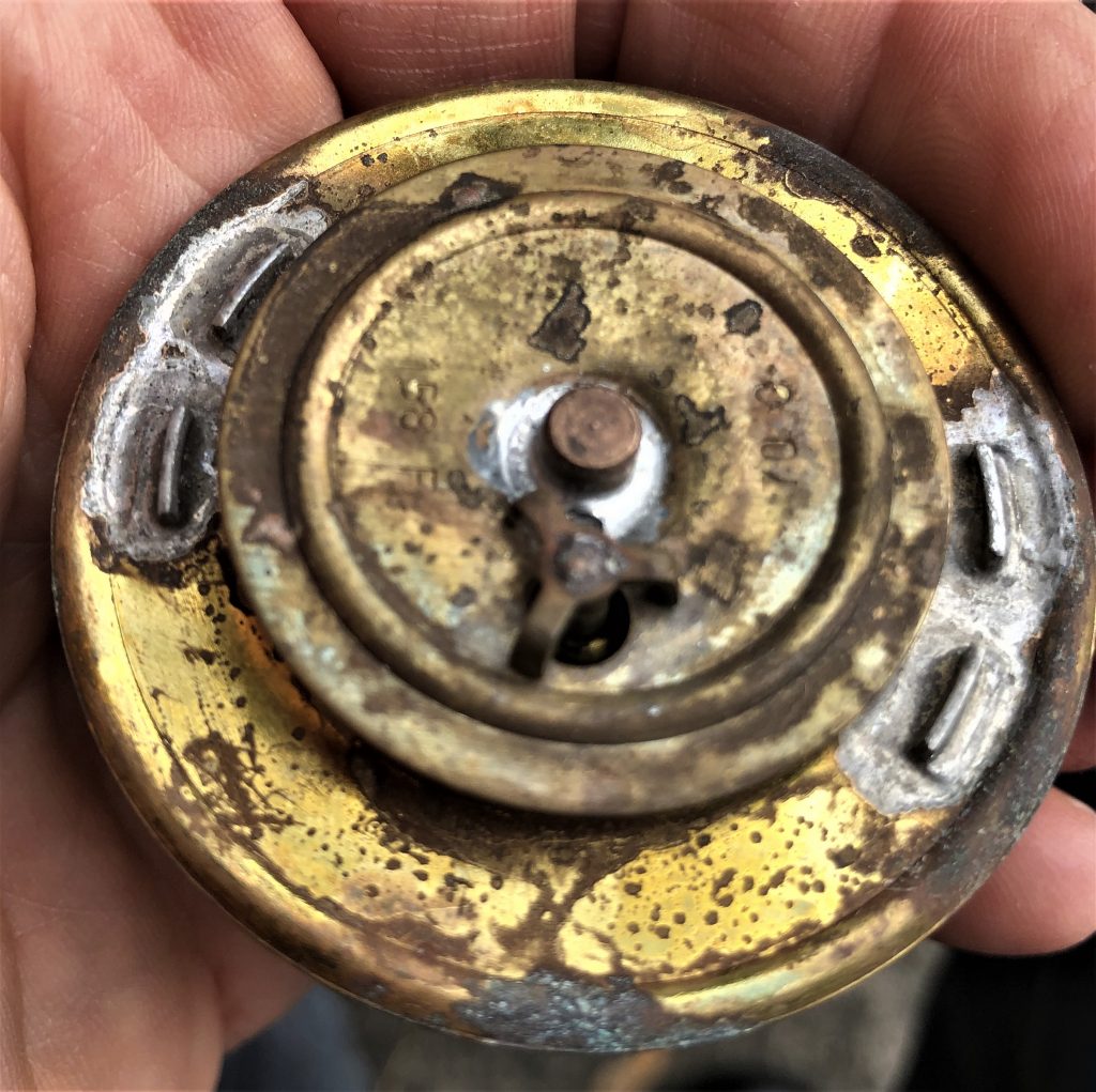 GH thermostat box Top side is tamped 156 F and 70 C
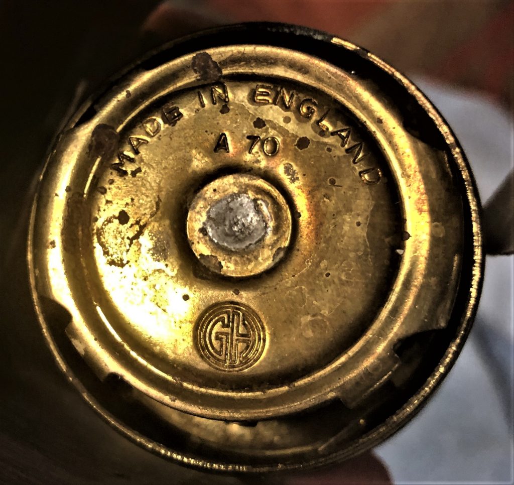 Bottom side is identical to other Quinton Brivec types but stamped GH
Mounting position of thermostats
All thermostats described in this article have a small hole in the valve. The thermostat should be positioned such that the small hole is always on top, to allow air (bubbles) to escape from behind the thermostat during the refilling process.
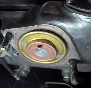 Small hole correctly positioned at top (XK 140)

Non screen bellows-type thermostats
Although a “bellows-type” thermostat, this version has no screen around the bellows to block the water opening like the original version and is not recommended for the earlier XK engines. They have been supplied by Smiths, AC and Quinton Hazell. In reverse it is, however, possible to use the earlier “bellows” type with screen (e.g. C3731/1) on the later engines.
Smiths 85032/70 and /80, 85035/78
Available with opening temperature of 70° C (158 F), 78° C or 80° C (176 F) and others.
 Smiths (non-screen) 85035/78 in 2nd generation “Superstat” box

AC (DELCO) TC range of thermostats
AC-DELCO had a large range of bellows thermostats without a screen. The programme comprises the following types:
- TC1 – 80c
- TC2 – 72c
- TC3 – 80c
- TC4 – 77c
- TC5 – 86c
- TC6 – 72c
- TC7 – 72c
- TC8 – 80c
- TC11 – 80c
- TC12
- TC14 – 80c
 AC thermostat of the “non-screen” TC type Still available but incorrect

Quinton Hazell QT 101 and 201 series
Available as QT 101/70 and QT 101/80 with opening temperature of 70° C (158 F) or 80° C (176 F). Also QT 201/86 is available as a “winter thermostat”.


QT 101/72 QT 101/80 QT 201/86
New aftermarket thermostat with sleeve: correct type!
Recently some suppliers introduced a correct type of bellows thermostat with sleeve. This version is apparently intended for the MGA, but looks to fit Jaguar XK’s as well. This is an almost exact copy of the original thermostats and functions correctly.
Perfect copies. (Photo courtesy Bob Richards)
New aftermarket thermostat with sleeve: incorrect type!
The sleeve of this aftermarket thermostat (above LH) is positioned just below the upper fixation of the thermostat whereas with the original version (above RH) the sleeve is positioned at roughly 25 mm (1 inch) lower.
This type of thermostat (without the extra ring soldered to it) had been invented and produced by the Robertshaw company until about 1999. The extra brass ring has been added to the thermostat by a distributer who modifies the thermostat for use in ‘British’ applications.
At the above photo (courtesy Robert B.) we see that the by-pass opening just below the surface is open when the thermostat is closed. This implies that the coolant remains within the engine to shorten warming-up time. When the thermostat commences to open the screen moves upwards (to the right on the above photo) and gradually shuts the by-pass. Coolant now flows from the engine to the radiator only. In case of the aftermarket type used in a Jaguar XK engine, the by-pass is blocked by the screen meaning it will take much longer before the engine gets warm.
In addition, early XK engines have a “mixture enrichement device” for cold starts. The time during which extra fuel is supplied to the engine is controled by an “Otter switch” that will stop the enrichement the moment the cooling fluid reaches a temperature of about 35C at the position of the Otter switch. It is evident that when the by-pass is not closed, it will take much longer before the mixture enrichement period will be ended. A too rich mixture lead to inregular running of the engine (and does certainly not contribute to a better environment!).
All other bellows or wax-type thermostats without a proper screen will warm-up quicker than the above “after market type”, but the by-pass will remain open at all times meaning a part of the coolant-flow remains within the engine and will not pass through the radiator. The use of these types of thermostat normally results in a higher coolant temperature!
XK’s cooling system conversions
Early XK engines had a cooling system pressure of about 4 lbs./sq.in. Newly developed engines in the 60’s had an increased cooling system pressurization (of at least 7 lbs./sq.in.) and the higher system pressure negatively affected the functioning of the bellows type design as it relied on expanding gases within the bellows.
So in case you have modified your cooling system (and increased the pressure), it is advised to replace the bellows-type thermostat for a wax-type thermostat. Fitting a separate blanking sleeve (that blocks the by-pass) would be an option to compensate for the absence of the sleeve. This may overcome the coolant temperature-rise that normally results from using a “non-sleeved” bellows thermostat.
