Category Archives: 01. General Information
Derrington steering wheels 1950’s
1 Reply
Derrington steering wheels for 1950’s Jaguars
This article attempts to summarise (in a structured way) information published on the subject of Derrington steering wheels, gathered from various sources.
Chapter 1 The Derrington company
V.W. Derrington Ltd. has been established around 1919 in New Malden, Surrey, England (about 12 miles south-east of London) initially tuning motor cycles of that era. By 1926 they moved to nearby Kingston and became successful in developing and supplying tuning components like manifolds, exhaust pipes, cylinder heads, and other mechanical improvements for automobiles as well as luggage carriers. From 1933 onwards Derrington advertised with steering wheels as part of their business activities.
Victor William Derrington had been a (motorcycle and automobile) race driver himself for many years, allowing him to exploit his racing experience for developing tuning equipment.
After WW2 there were two “fast runners” made at the Derrington works at London Road in Kingston: Derrington luggage racks and Derrington wooden steering wheels available for many models of the 1950’s and 1960’s. According to “Motor Sport” magazine of December 1959, Derrington employed at that moment eight people full time in the production of steering wheels.
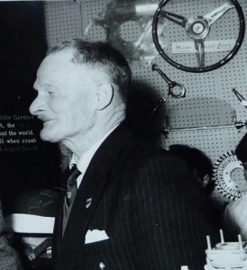 Vic Derrington at the 1961 Racing Car Show; note steering wheel at display

Note that over 60% of Derringtons production was exported, the majority to America. The steering wheels were especially popular in the States and several hundreds have been exported every year from about 1953 onwards. Orders for the USA could only be supplied through their West and East Coast agents: Vilem B. Haan in Los Angeles (CA) and Wilco of Rochester (NY).
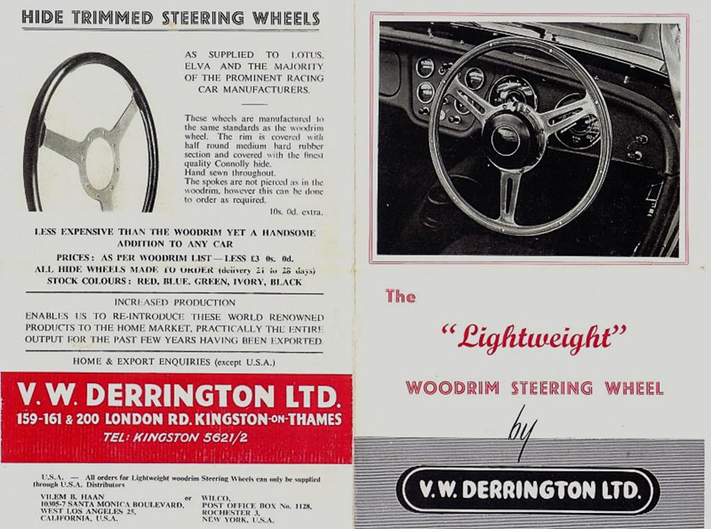
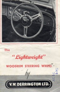 Front of a 1960 brochure

Chapter 2 The “Derrington wheel” and similar wheels
Although Derrington made steering wheels with various spoke configurations, the company became famous for one particular model that we now call the “Derrington wheel”. The specification of (and additional information on) the “Derrington wheel” is provided in Chapter 3.
As production volume increased, Derrington started to outsource some of the steering wheel activities. By the end of the 1950’s another steering wheel manufacturing company Moto-Lita was capable of providing “Derrington” steering wheels, however it is believed that Moto-Lita made wheels in those days were not of the same high quality as Derrington manufactured wheels.
We may assume that Derrington gradually moved away from steering wheel production, fully concentrating on their successful tuning activities. Probably in the late 60’s Derrington completely ceased their steering wheel production activities and Moto-Lita continued the manufacturing of the typical “Derrington wheel” however always characterised by their standard nine hole centre mounting (see Chapter 4).
A similar wheel was offered by the Donald Healey company for their (Austin-Healey) sports cars, which may lead to confusion. This wheel is therefore further described in Chapter 5.
Finally, the name Derrington is often linked to a Jaguar woodrim steering wheel that was available as an option for the Mk 2. However, this was not the “Derrington wheel” but a different model as is described in Chapter 6.
This brings us to the following timeline for the Derrington (style) wheel:
- 1953/54 onwards: the “Derrington wheel” manufactured by Derrington in 15, 16 and 17” diameter
- 1955 onwards: Donald Healey manufactured “Derrington style” steering wheels
- 1959/60 onwards: Moto-Lita manufactured wheels for Derrington (and Donald Healey)
- 1960 onwards: Jaguar Mk 2 Derrington steering wheels (different style with non slotted spokes)
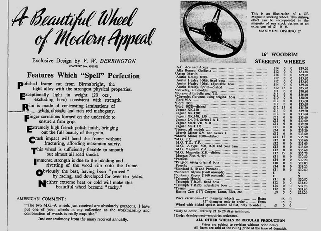
Chapter 3 The “Derrington wheel” specification
Around 1953/1954 Derrington started the manufacture and delivery of the “Derrington wheel”. The design itself shows some resemblance to an earlier Italian manufactured Nardi model with three slotted spokes, however not with the characteristically 3 x 120° even spacing of the Derrington wheel.
Derrington had a patent applied for the making of wooden steering wheels on October 18, 1954 and granted on October 5, 1955.
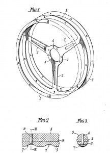 Original patent application of October 18, 1954

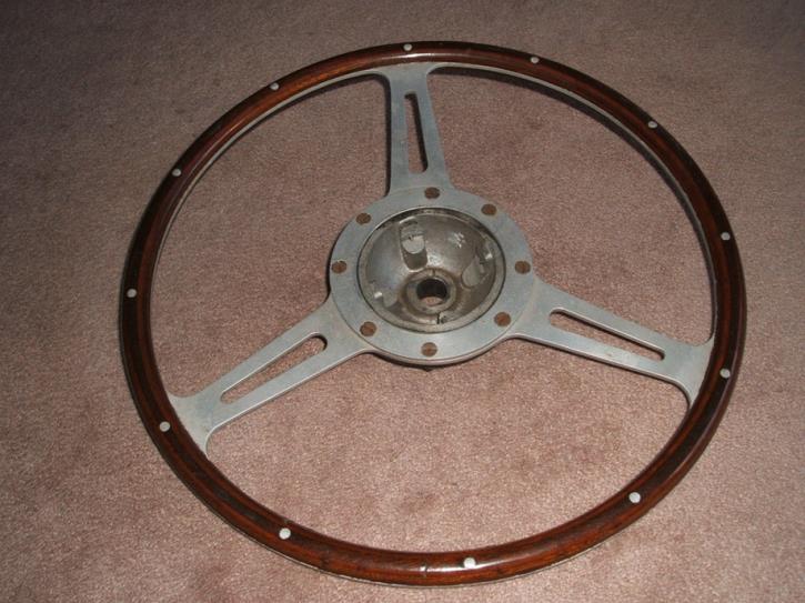
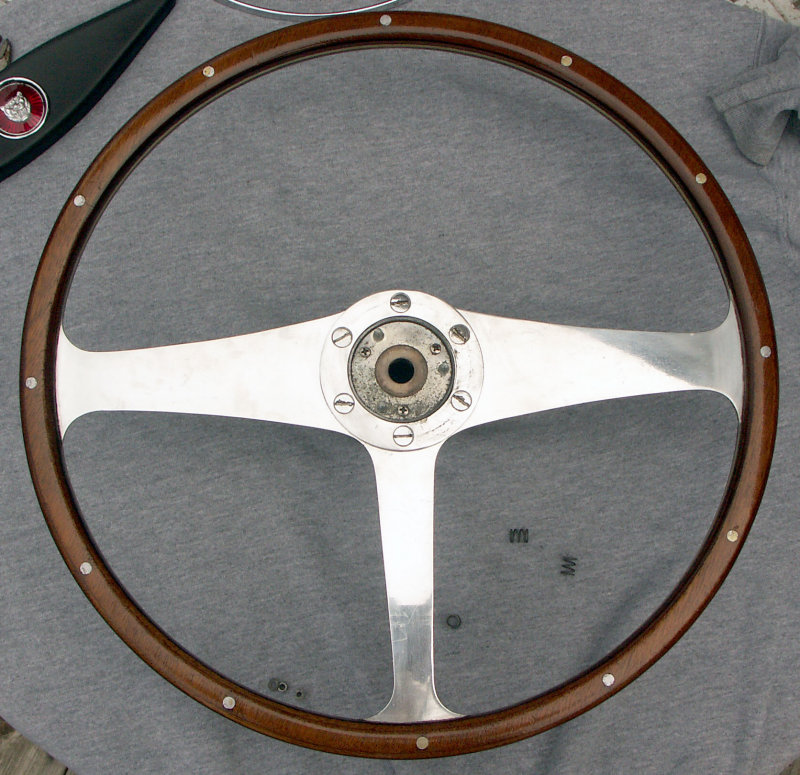
Specification and characteristics of the original “Derrington wheel”:
- three (slotted) “Birmabright” aluminium spokes with even (3 x 120°) spacing
- flat (non-dished) version
- eight-hole centre mounting with 8 flat CSK slotted screws and nuts (BSF 3/16 – 32 ?)
- laminated rim from mahogany and either obeechi or white sycamore
- (nine or) twelve rivets in the laminated rim
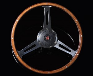
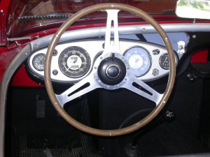
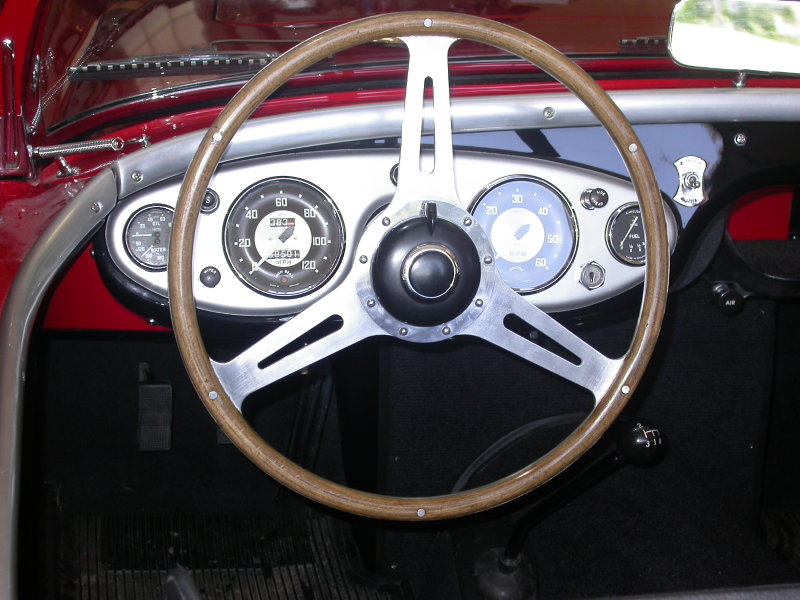
The “Derrington wheel” was standard delivered in 16″ diameter, but 15″ and 17″ versions were available to special order. There are also examples of original Derrington manufactured wheels that had a 9 hole centre mounting.
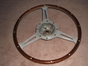
 Original Derrington 16” wheel with 8 screw mounting and 12 rivets.
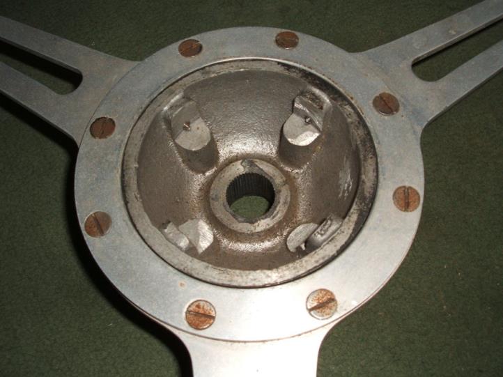
The frames of the wheels were cut from Birmabright (an alloy of aluminium and magnesium with 7% magnesium and 1% manganese; also known as BS NS4, American 5251 and ISO AlMg2), and the laminated wooden rims were riveted to the frame. The laminated woodrim consisted of African Obechi wood and Mahogany. The boss (or hub) is cast from aluminium (mostly LM6) and machined to fit each particular model.
There have been many discussions over the past decades, whether this Derrington wheel was a genuine Jaguar factory option or not. Although apparently more was possible at Jaguars (including a “Bluemels wood rim steering wheel”) than one would understand from the “optional extras” 1958 list, the general opinion is that wooden steering wheels were not available as a factory option, until around 1960 when Jaguar offered a wooden steering wheel for the Mk2 (part number C.25198), but we know that this is actually not the even spaced “Derrington wheel”. Part number C.25198 is mentioned in spare parts bulletins and parts catalogues as well.
We also know that the “Derrington wheel” was rather popular in the 1950’s and was advertised in many car magazines, including those in the USA. Reference is made of the June 1960 issue of Sports Car Illustrated containing ads for the “Well Known Derrington Racing Steering Wheel”. We referred already to the two US Derrington importers, which indicates that Derrington wheels were freely available in the USA. So therefore we may assume that a (large?) number of XK’s may have received an aftermarket Derrington wheel in the 1950’s. Whether or not there was any “active support” from Jaguar USA in supplying these steering wheels remains unclear. Dealers however may have recommended these Derrington wheels themselves in order to increase sales.
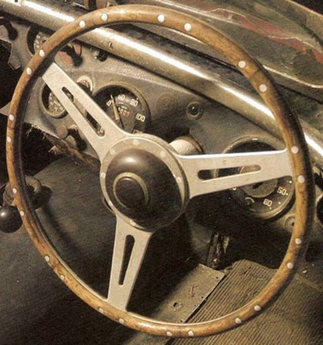
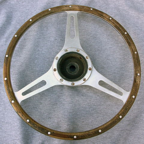
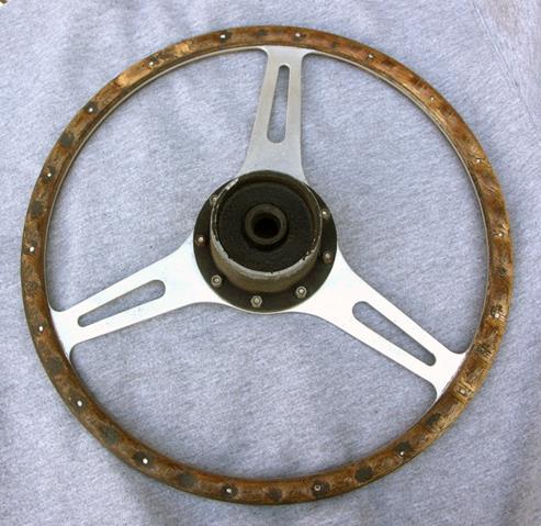
 Early Derrington wheel with 8 screw mounting.
The Derrington brochure (shown below, probably dated 1960) not only lists the prices in Pound Sterling but also in US Dollar, which further supports the active marketing policy of Derrington in the USA. Also note the text in the brochure that “practically the entire output for the past few years having been exported”. This may further clarify the presence of Derrington wheels on US Jaguar XK 120, 140 and 150 in the 1950’s.
The list with (only European) car brands and types in the Derrington brochure is long and all Jaguar versions from the period 1950 to 1960 have been listed.
Chapter 4 Moto-Lita manufactured wheels for Derrington (~ 1960 onwards)
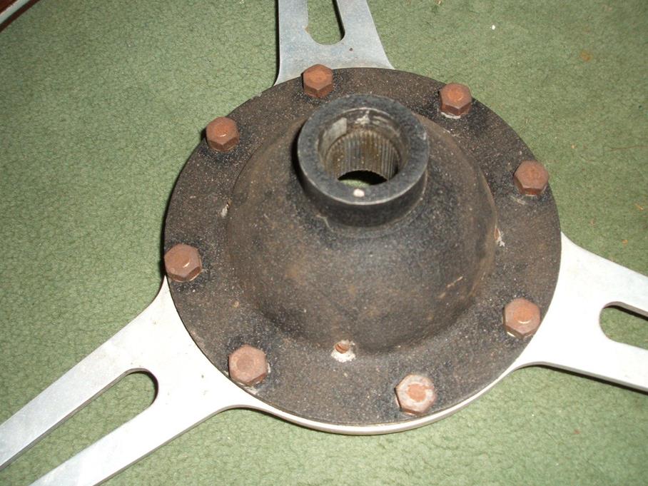
Around 1959 Moto-Lita started making steering wheels for Derrington including the famous “Derrington wheel”. Some say that Moto-Lita made wheels of that era were not of the same high quality as Derrington manufactured wheels. Moto-Lita continued the use of 12 rivets but it is unclear whether Moto-Lita was requested to continue the use of 8 bolt centre mounting or that these wheels immediately switched over to the 9 bolt centre mounting boss/hub as already made by Moto-Lita.

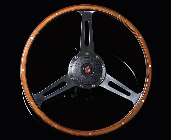
Above is a photo of a 1960’s Derrington wheel made by Moto-Lita. Diameter is 16 inches. It uses the Moto-Lita style hub with 9 screws. Moto-Lita still manufactures the “Derrington wheel” today and adheres to the original design although with 9 bolt centre mounting (see photo below).
 Modern Moto-Lita “Derrington wheel”
Chapter 5 Donald Healey manufactured “Derrington style” steering wheels (~ 1955 onwards)
The story goes that Donald Healey aimed at in-house production of 16” woodrim steering wheels for the Austin Healey 100 series. The designs were made by Gerry Coker and the first models were manufactured in-house. There were in fact two designs: one with drilled and one with slotted spokes. The latter has a very close resemblance to the “Derrington wheel” with even spaced spokes.
These first versions (also used on the AH 100 Le Mans cars) were made of six separate solid wood segments (not laminated) fixed to the aluminium frame by 4 rivets for each of the 6 per segments (so 24 rivets in total). They had a 9 bolt centre mounting (like Moto-Lita).
 Original AH 100 Le Mans “segmented” wheel with 9 screws and 24 rivets in “Derrington” style
The AH 100M could be delivered with the slotted spoke version as a factory option. These wheels were no longer made by Donald Healey but manufactured by the Coventry Timber Bending Co. Ltd . The Coventry Timber Bending Company was a manufacturer of “laminated and solid wood work for cars and boats”. The company had been established in 1938 by their directors: H. E. Newsum and L. G. Hains. They started activities at Swallow Road, Holbrook Lane in Coventry, but later moved to new premises about 5 miles to the east, at Bodmin Road, Walsgrave, also in Coventry. In 1954 they also produced the D-Type Jaguar steering wheel and from 1961 produced the E-Type steering wheel as well. In 1984 the company became Insolvent and was wound up.
The Coventry Timber Bending Co. manufactured “Derrington style” woodrims were made of beech and had only six rivets to fix the wood. The aluminium frame was initially riveted (not bolted) to the boss.
(See for more info: Autocar of December 2, 1962)
 Strong resemblance, but not Derrington!
The steering wheel with drilled spokes became the standard wheel on the 100S production cars.
Around 1960 Moto-Lita began to supply “Derrington” style steering wheels to Healey, which now had 18 rivets instead of 24 for the in-house manufactured versions or instead of 6 as made by Coventry Timber Bending. These Moto-Lita steering wheels were Healey badged (or stickered).
Most likely the above photos show the later Moto-Lita made “Derrington wheels” supplied to Donald Healey with 9 screw mounting and 18 rivets! The 6 segment solid wood method has been replaced by a laminated circular construction.
Chapter 6 Jaguar Mk 2 Derrington steering wheels (different style with non-slotted spokes)
Jaguar, possibly aware of the lively interest in woodrim steering wheels, offered a special 17-inch lightweight, wood-rim steering wheel manufactured by Derrington. It seems that this version was manufactured at the explicit request of Jaguar for use to special order on Mk 2 cars.
![]()
The Birmabright spokes had been polished and the woodrim of contrasting laminations of white obeechi and rich red mahogany were clear lacquered to bring out the grain. The Jaguar wheel was priced at £12 and it takes the standard Jaguar Mk 2 half horn-ring.

Wire wheels: worn hub and wheel splines
Wire wheels on Jaguar XKs
All Jaguar XK’s of the Special Equipment version were supplied with 16” wire wheels starting 1951. Also standard cars could have wire wheels as a factory option from that moment onwards.
 Early Rudge Whitworth wire wheel

Wire wheel fixation
Detachable wire wheels have a different way of fixation compared to normal disc wheels, as they are mechanically “connected” to the axle hubs in two ways:
1. In a rotational direction by means of driving splines (serrations) on the (stub) axle hubs and driven splines on the inner wheel centre.
2. In an axial way by means of a (threaded) locking nut preventing the wheel to become disconnected from the threaded axle hub.
This article will not tackle the subject of which wire wheel types have been applied by Jaguar over the years; see the appropriate literature for that. We do want, however, to emphasise the potential danger of wire wheel fixation systems after many years of use (and abuse) to the point where they may become even highly dangerous! In addition, some guidance is provided in checking whether a wire wheel can still be safely fixed to the car.
![clip_image002[4]](https://www.bobine.nl/jaguar/wp-content/uploads/2014/05/clip_image0024.gif "clip_image002[4]")
A – Locking thread on hub (left or right hand thread).
B – Driving splines on hub.
E – Driven splines of wheel centre.
Rudge-Whitworth fixation
The system of detachable and interchangeable wire wheels has been initially designed by John Pugh around 1910 but is better known under the (company) name of Rudge-Whitworth.
The resulting standardisation of detachable wire wheel fixations in Europe dates back to the 1920’s. The basis for this standard was the load to be carried per wheel and the required bearing diameter for that, resulting in a certain cross section for the hub. Note that the wheel type designation in the standard are basically structured around the (metrical!) dimensions of (then available) wheel bearings.
![clip_image002[6]](https://www.bobine.nl/jaguar/wp-content/uploads/2014/05/clip_image0026_thumb.gif "clip_image002[6]") Very early 1912 advertisement
Very early 1912 advertisement
![clip_image002[6]](https://www.bobine.nl/jaguar/wp-content/uploads/2014/05/clip_image0026.gif "clip_image002[6]")
Wear on splines and thread
Over the years the thread of the locking nut and the hub itself may wear but (even more important) the splines on the hub and in the wire wheel centre may wear to the extent that the construction eventually becomes unsafe. Therefore it is wise to regularly check them and more in particular during any XK restoration as the condition and history of axle hubs and wheels are unknown.
Four dimensions are of importance here and have to be checked:
1. The maximum allowed inner diameter of the thread of the lock nut
2. The minimum allowed outer diameter of the thread on the wheel hub
3. The minimum allowed outer diameter of the splined hub
4. The maximum allowed inner diameter of the inner wheel centre splines
Please note that wear of splines and thread is accelerated if the wheel is not fitted tightly!
Cross-section of Rudge-Whitworth hubs
The principle wheel type designation according the Rudge-Whitworth standard refers to the maximum size of an outer wheel bearing (in millimetre) which can be used with that hub. The actual hub diameter is measured across the outside of the splines on the axle hubs ( not the wheel splines).
|
Wheel Type |
Actual hub diameter |
Number of splines |
Spline length Short Hub |
|
35 |
52 |
62 |
36 |
|
42 |
62.5 |
75 |
37 |
|
52 |
73 |
88 |
37 |
|
62 |
82.5 |
100 |
57 |
|
72 |
92 |
112 |
55 |
|
80 |
102 |
124 |
58 |
|
90 |
111.5 |
136 |
56 |
|
100 |
123 |
150 |
59 |
|
120 |
137 |
168 |
63 |
Two wire wheel types are normally used on British sports cars: type 42 and 52. Jaguar opted for their post-war cars for the Type 52 wire wheels. The (course) thread of Jaguar wire wheels has a top angle of 60° and a pitch of 8 TPI (or 3.2 mm).
 Rear wheel splined hub Jaguar XK 140

Dimensional requirements for Type 52 wire wheels: worn or still OK?
Further to the aforementioned important testing criteria, the survey below gives specific information regarding when a splined hub, wire wheel or locking nut should be replaced.
- The locking nut should be checked for wear on the (internal) thread. If a cylinder with an outside diameter of 2.627” or 66.7 mm should fit in the locking nut, wear has progressed to the extent that the locking nut has to be replaced.
- If a tube with an internal diameter of 2.707” or 68.8 mm fits over the thread of the axle hub, wear has progressed to the extent the complete hub has to be replaced.
- If a tube with an internal diameter of 2.840” or 72.1 mm fits over the splines of the axle hub, the complete hub has to be replaced.
- If a cylinder with an outer diameter of 2.790” or 70.9 mm fits in the internally splined wheel centre, the complete wire wheel has to be replaced.
Note that the above dimensional requirements are no more than minimum requirements! As an example: wire wheel constructions fulfilling the above requirements have a remaining overlapping contact height of the splines of no more than (72.1 – 70.9 =) 1.2 mm. Although the contact surface is of course larger due to the 60° V angle of the spline and the length of the spline (here 37 mm), in comparison a new type 52 spline has a contact height of 72.9 – 70.2 = 2.7 mm, meaning that the (safety?) margin has been more than halved.
So don’t use any hubs or wheels with spline dimensions below the above given minimum requirements!
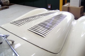
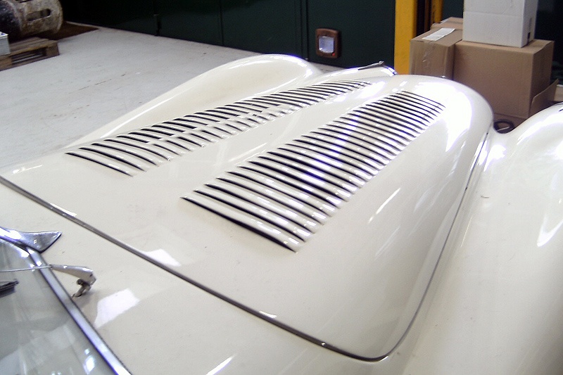
Bonnet louvres for XK 140
Bonnet Louvres for XK 140
Louvres
One of the ways to keep the coolant temperature under control is to increase the amount of air through the radiator. Next to installing an electric cooling fan, bonnet louvres may help (of course under the condition that the car is moving). The latter solution also doesn’t consume any power from the engine. This is the reason why in particular race cars (including Jaguars) had louvres installed in bonnet and/or wings.
Jaguar XK’s
Jaguar used this principle for their XK’s and installed louvres in various versions that took part in active racing. In particular during the early years, C-types and some XK 120’s received this option, but there are also at least two examples of the same operation for the XK 140.
Dimensions
It is rather difficult to obtain exact data on the position, number and size of the louvres in the bonnet of the XK120 and the C-types. Furthermore, we note that the dimension’s differed per type and per year because they were made by hand and the development of the cars continued of course. What becomes clear, however, is that there are always two rows of louvres symmetrically located at both sides of the middle of the bonnet.
(All dimensions given here serve to help getting a better insight, but claim in no way to be exact).
Louvres for XK 120’s
Most prominent example is Clarck Gable’s second XK 120: a 1952 steel-bodied OTS with chassis number 672282. After his complaints regarding the lack of ventilation in the engine compartment Jaguar punched two rows of slots in the bonnet (see below).
 Louvres in Clarck Gable’s 2nd XK 120
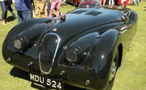
Jaguar XK 120 OTS Works Competition car with registration MDU 524, had a different bonnet louvre pattern. This originally May or June 1952 built RHD OTS with chassis number 660986 is well-known after it had been extensively modified in 1953 to become the streamlined car that set a speed record of 173.159mph on the Jabbeke motorway in Belgium. Before and after that event it participated in a more standard execution in many races in the UK driven by Albert Powell and Brian Redman.
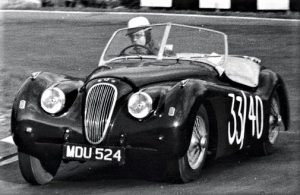
 Albert Powell in MDU 524 in 1957 MDU 524 with its 1953 streamlined body in 2014
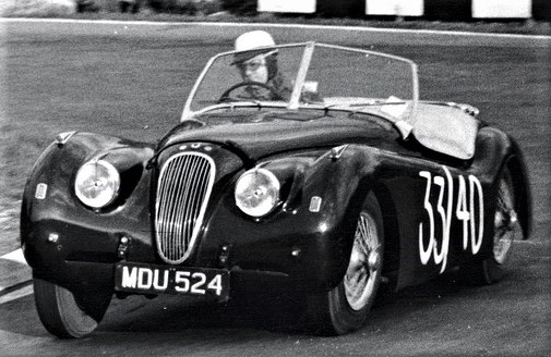
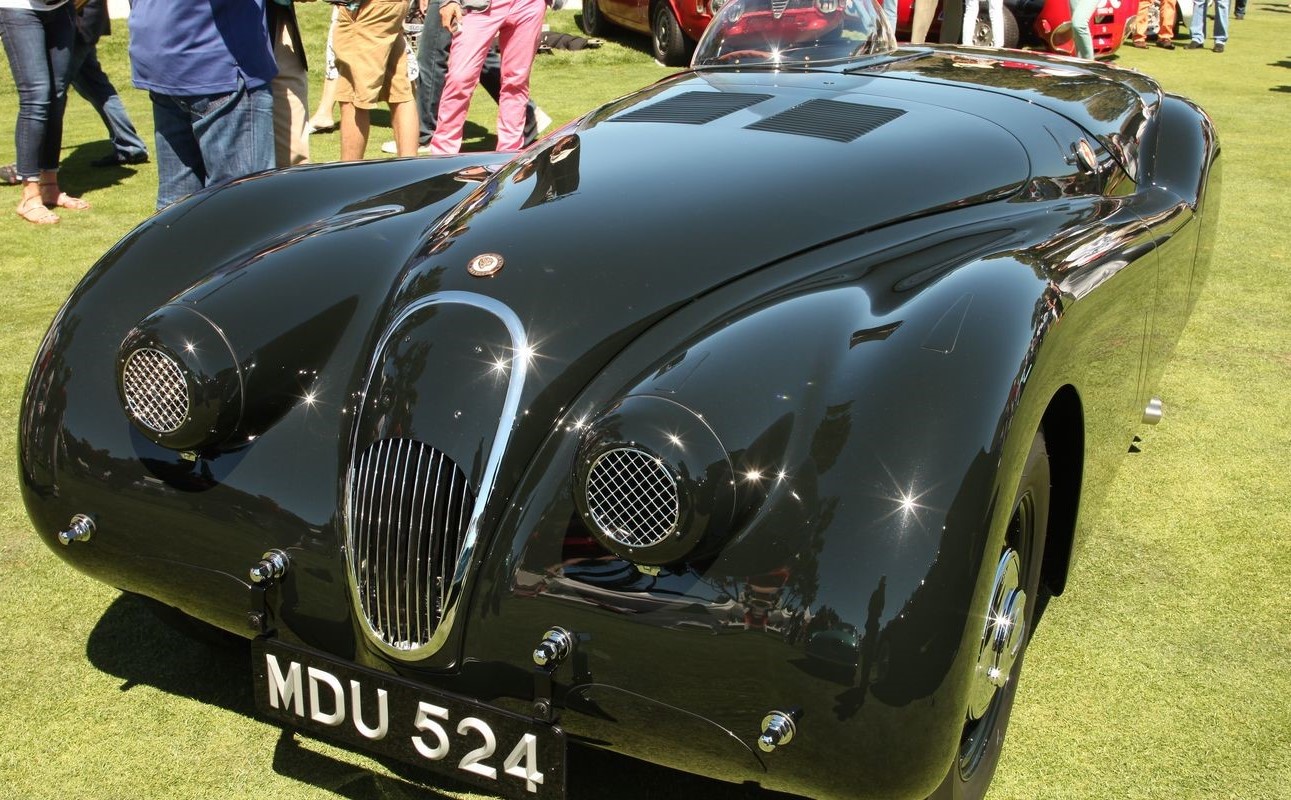
Whereas Clarke Gable’s car had triangular shaped louvres almost over the entire bonnet length, the MDU 524 louvres have an almost square lay-out, much more in line with the later XK 140 patterns (as we will see below).
Louvres for XK140’s
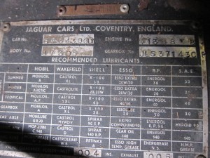
Most prominent example of an XK 140 FHC with bonnet louvres is the 1956 Le Mans car driven by Peter Bolton and Bob Walshaw: registration number PWT 846 and chassis number S 804231 DN. This was a SE version in standard form with apart from the optional 2” H8 carburettors and an additional fuel tank, also got extra air intakes at the front and louvres in the bonnet.

Clausager in his book “XK 140/150 in detail” shows a detailed photo of the louvres which reveals that they have not been made straight in the aluminium bonnet material itself but made in a separate plate and mounted from behind in an opening cut in the bonnet. The louvres are pushed through from the inside and the air opening is in the direction of the windscreen. We count (two times) 16 louvres with an estimated width of 185 to 190 mm (7¼ to 7½”) over a length of about 445 mm (roughly 17½”). This implies that the individual louvres are about 28 mm (1.1”) wide with an opening of about 12 mm (½”). The louvres are placed very close to each other without any space between them (which somewhat reduces the mechanical strength of this section and louvres can be easily bend).

Regarding the exact location of the louvres on the bonnet, the position on the Le Mans car is towards the end of the bonnet close to the windscreen. This was only possible by removing the aluminium reinforcement construction on the inside of the bonnet and welding it back after the louvres have been placed (what may restrict the air flow).
The second example of an XK 140 with bonnet louvres is an early “experimental” OTS (most likely chassis number S 8000033 DN). This car had two additional air intakes at both sides of the grill above the bumper and bonnet louvres, very much in line with the Le Mans car (which was a much later car). It is impossible to reproduce the exact measurements of these louvres, but they seem to be close to the ones of the Le Mans version.

Louvres in C types
Looking at photos of C types we see for the 1953 versions a different pattern for the louvres: two groups of 22 louvres over a total length of about 610 mm (24”) and a width of 210 mm (8¼”), meaning 28 mm per louvre which is identical to the spacing used for the XK 140 (same tooling?).
Making bonnet louvres in an XK 140
When making louvres in an XK 140 bonnet, there are two alternative ways to go:
1. Making two separate plates with louvres and fix those in an opening cut in the bonnet.
2. Making the louvres straight in the bonnet.
When opting for the second method, limitations are created by the reinforcement construction at the inside of the bonnet: the louvres cannot be placed as close to the windscreen as was the case for the Le Mans and Experimental car. And the total available length for the louvres between two reinforcement brackets, allows only for about 10 openings (spaced at a distance, because a certain strength of the bonnet will be appreciated!). The louvres are cut and formed with a special tool and machine (see photos) and the result is very satisfying.
![clip_image002[4]](https://www.bobine.nl/jaguar/wp-content/uploads/2013/06/clip_image0024_thumb.jpg "clip_image002[4]") Making the louvres with a special tooling
Making the louvres with a special tooling
![clip_image002[4]](https://www.bobine.nl/jaguar/wp-content/uploads/2013/06/clip_image0024.jpg "clip_image002[4]")
![clip_image004[4]](https://www.bobine.nl/jaguar/wp-content/uploads/2013/06/clip_image0044_thumb.jpg "clip_image004[4]") Final result (before painting)
Final result (before painting)
![clip_image004[4]](https://www.bobine.nl/jaguar/wp-content/uploads/2013/06/clip_image0044.jpg "clip_image004[4]")
Spare wheel lid mounting screws
Spare wheel lid mounting screws NS 519/3D
The hinges (BD9374) are mounted to the spare wheel lid (BD9372 or BD11262) with (3 x 3=) 9 countersunk set screws and fit in “T” nuts (BD9909/1) placed in the plywood.
 Hinges are fixed to these “T” nuts with ANF 3/16 thread
Official Jaguar code for the mounting screws is NS519/3D meaning ANF 3/16 x 3/8” CSK slotted set screw. However, since about 1950 the 3/16″ UNF thread doesn’t exist any longer. There are 3 possible alternatives:
- The best equivalent is CSK Slotted No.10 x 32 threads per inch. Diameter for UNF 3/16″ is 0.1875″ and for No.10 is 0.190″. They are however interchangeable and have both the same 55° thread angle.
- British Standard Fine (BSF) has a 3/16″ x 32 thread as well. Normally UNF and BSF have different “thread per inch” but in this case they are identical.
- Also 2BA screws might fit if the thread hole is undamaged: it is about 0.1 mm smaller in diameter and (as the thread angle is only 47.5°) it will fit the UNF thread. The pitch is slightly longer (about 0.02 mm!) than the UNF version.
|
Thread |
Diameter (inch) |
Diameter (mm) |
Pitch (TPI ) |
Pitch (mm) |
|
ANF 3/16” |
3/16” |
4,763 |
32 |
0,79 |
|
No 10 |
0,190 |
4,83 |
32 |
0,79 |
|
BSF 3/16” |
0,187 |
4,75 |
32 |
0,79 |
|
2BA |
0,185 |
4,70 |
31,35 |
0,81 |
Additional information on these thread types:
BSF has a Whitworth 55° thread angle, where as BA has a 47.5° thread angle. So these threads are not automatically interchangeable: in general a BA screw might fit a BSF thread hole if the diameter and TPI are close.
BA is taken from the 19th Century Swiss Thury thread. Its formulation was proposed by the British Association in 1884 and adopted in 1903. BA has in principle metric dimensions. No.0 BA is 6.0 mm diameter and subsequent numbers are in 0.9 progression. Multiply a BA diameter by 0.9 and you have the diameter of the next smaller size. BA screws are nowadays seldom seen and virtually exclusive to electrical fittings (e.g. Lucas) and instruments (e.g. Smiths).
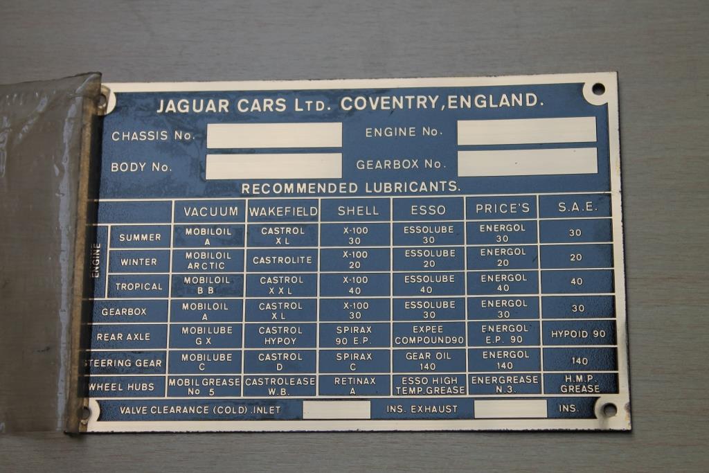
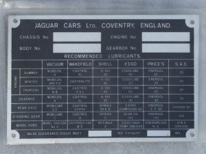
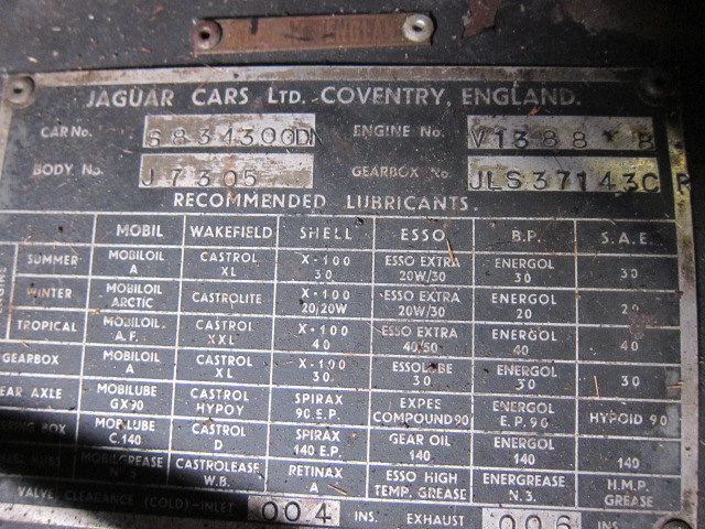
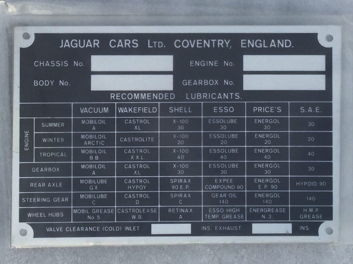
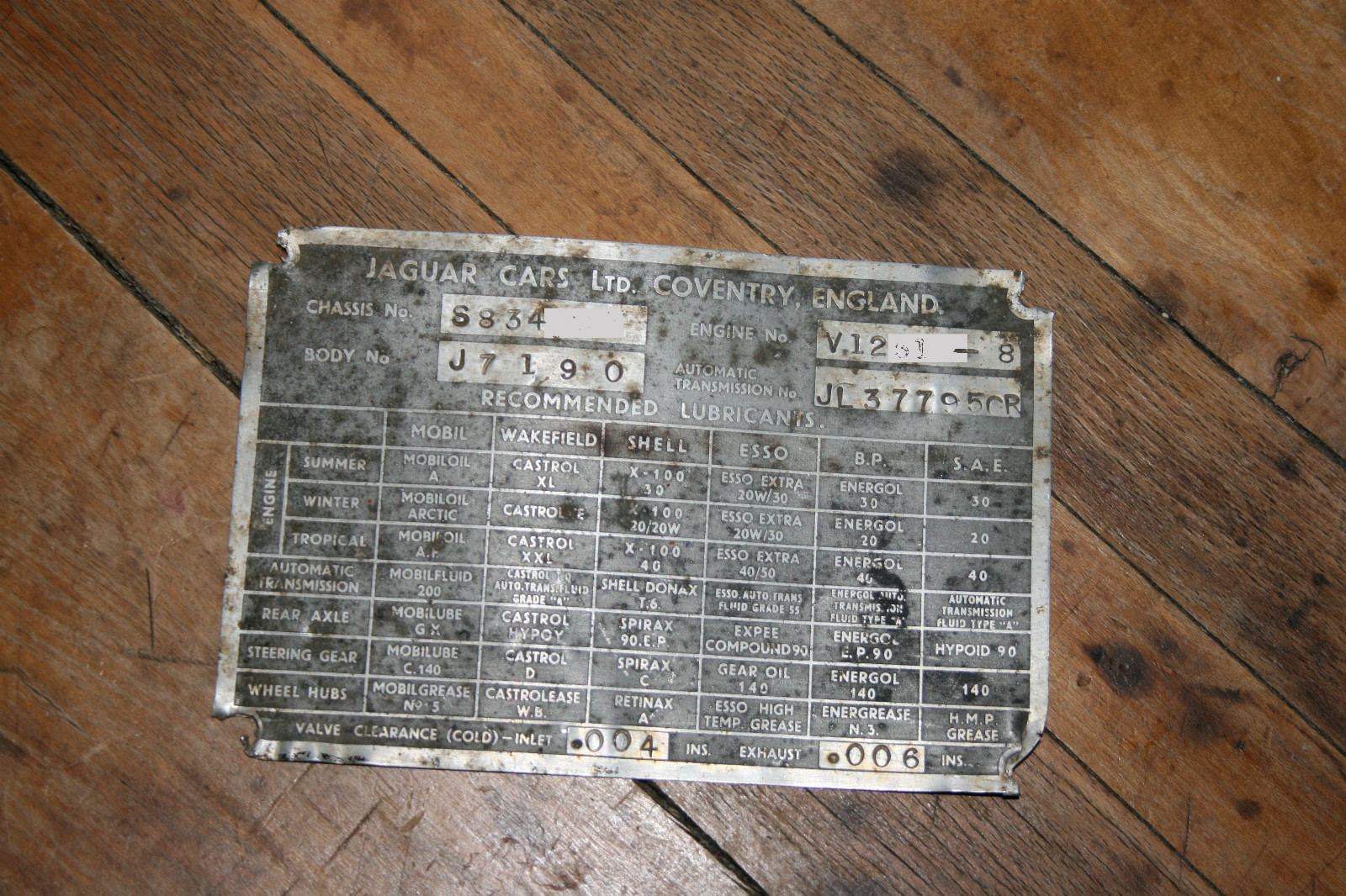
Jaguar Identification or Chassis Plates
Overview of Jaguar Chassis Plates used from 1946 to 1974
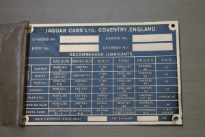
Jaguar used various types of Chassis (or Identification) Plates in the post WW2 period. The changes in dimension and lay-out of the plates were mostly the result of changes in available space when new models were introduced, but also due to changing brand names of lubricant suppliers or their respective products.
When focusing on the changes related to Chassis Plates we may conclude that the most apparent change relates to size and orientation of the plates in 1948. In the years before a smaller brass plate (Type A, 3½ x 4″) was vertically positioned containing relevant car data and accompanied by a similarly sized plate containing lubricant recommendations.
From the launch of the XK 120 in 1948 the plates were larger and had a “horizontal format” with both car data and lubricant recommendations combined on one plate. The initial size of this plate (Type B, 6½ x 4¼”) as used for the Jaguar Mk V, was apparently too large as it was reduced in October 1949 (Type C, 5¾ x 3¾”).
This then became the standard format for over a decade, with only a change-over from brass to aluminium in 1957.
| Type No | Dimension | Material | Used on | Year |
| TYPE A.1 | 3½ x 4″ | brass | Mk IV | 1946 |
| TYPE A.2 | 3½ x 4″ | brass | Mk IV | – |
| TYPE A.3 | 3½ x 4″ | brass | Mk IV | – |
| TYPE A.4 | 3½ x 4″ | brass | Mk IV and very early Mk V | – |
| TYPE B.1 | 6½ x 4¼” | brass | Mk V, very early XK 120 | 1948 |
| TYPE C.1 | 5¾ x 3¾” | brass | XK 120 | From October 1949 |
| TYPE C.2 | 5¾ x 3¾” | brass | XK 120 | From March 1952 |
| TYPE C.3 | 5¾ x 3¾” | brass | XK 120 | From August 1952 |
| TYPE C.4 | 5¾ x 3¾” | brass | XK 120/XK 140 Manual | From October 1953 |
| TYPE C.5 | 5¾ x 3¾” | brass | XK 140 Auto | 1954 – 1957 |
| TYPE D.1 | 5¾ x 3¾” | alu | XK 150 Manual | 1957 – 1960 |
| TYPE D.2 | 5¾ x 3¾” | alu | XK 150 Auto | 1957 – 1960 |
| TYPE D.3 | 5¾ x 3¾” | alu | XK 140 Manual | only 2nd half 1957 |
| TYPE D.4 | 5¾ x 3¾” | alu | 4XK 150 Auto | only 2nd half 1957 |
| TYPE E.1 | 6½ x 3¾“ | alu | 1961? | |
| TYPE E.2 | 6½ x 3¾“ | alu | ||
| TYPE E.3 | 6½ x 3¾“ | alu | ||
| TYPE E.4 | 6 ½ x 3¾“ | alu | ||
| TYPE E.5 | 6 ½ x 3¾“ | alu | ||
| TYPE E.6 | 6½ x 3¾“ | alu | ||
| TYPE E.7 | 6½ x 3¾“ | alu | ||
| TYPE E.8 | 6½ x 3¾“ | alu | ||
| TYPE E.9 | 6½ x 3¾“ | alu |
Type A plates on Jaguar Mk IV

 Type A4. (?)


Type A plate on a 1948 Mk IV. Plate dimension: 3½ x 4″ . May also have been used on very early Mk V cars. Each of the 3 available engines had a specific plate. The lay-out shows only fields for CHASSIS No, ENGINE No and BODY No and is vertically oriented; all later plates have a horizontal orientation. There may have been 4 text variations for this plate (indicated with A1. to A4.) The recommendations for LUBRICANTS are shown on an identically sized plate next to the Chassis plate: VACUUM, WAKEFIELD, SHELL, ESSOLUBE and PRICE’S are mentioned here.

Type B plates on Jaguar Mk V
This new Chassis Plate measures 6½ x 4¼”, made of brass and plated with nickel. The lay-out has now 4 fields for CHASSIS No, BODY No, ENGINE No and GEARBOX No. The recommendations for LUBRICANTS remained unchanged: VACUUM, WAKEFIELD, SHELL, ESSOLUBE and PRICE’S, but an additional column has been added to show the S.A.E. viscosity. The recommendation from PRICE’S for the WHEEL HUBS was blank. To indicate the VALVE CLEARANCE two new fields have been created to be stamped per car type.
The overall lay-out was the basis for the later Type C plates.
Note: The Mk V manual contains one photo of a car with the smaller ID plate from the Mk IV era.
![clip_image002[4]](https://www.bobine.nl/jaguar/wp-content/uploads/2013/05/clip_image0024_thumb.jpg "clip_image002[4]") Type B1
Type B1
![clip_image002[4]](https://www.bobine.nl/jaguar/wp-content/uploads/2013/05/clip_image0024.jpg "clip_image002[4]")
Type B plates on Jaguar XK 120 (very early examples)
See data under Mk V. The same plate (Type B1) was used for a number of early XK 120 OTS versions.
Type C plates on Jaguar XK 120
Type C plates were identical to Type B plates but smaller in dimension. Four different Identification plates have been used over the life of the XK 120: C1 to C 4 (with B1 as the fifth variation for the very first XK 120’s).
The first plate (Type C1) showed a blank box for Price’s recommendation for Wheel Hubs lubrication, as was the case with the Type B plate.
![clip_image002[6]](https://www.bobine.nl/jaguar/wp-content/uploads/2013/05/clip_image0026_thumb.jpg "clip_image002[6]") Type C1.
Type C1.
![clip_image002[6]](https://www.bobine.nl/jaguar/wp-content/uploads/2013/05/clip_image0026.jpg "clip_image002[6]")
This was corrected with a temporary solution by riveting an “add-on” plate over the bottom two rows, now showing BELMOLINE H.M.P. on the empty space. This version (Type C2, see here under) lasted for about 6 months from March to August 1952.
![clip_image004[4]](https://www.bobine.nl/jaguar/wp-content/uploads/2013/05/clip_image0044_thumb.jpg "clip_image004[4]") Type C2.
Type C2.
![clip_image004[4]](https://www.bobine.nl/jaguar/wp-content/uploads/2013/05/clip_image0044.jpg "clip_image004[4]")
In August 1952 the” add-on” plate was replaced by a new plate (Type C3) fully identical to the Type C1 plate but now with BELMOLINE H.M.P. on the former empty space .
![clip_image006[4]](https://www.bobine.nl/jaguar/wp-content/uploads/2013/05/clip_image0064_thumb.jpg "clip_image006[4]") Type C 3.
Type C 3.
![clip_image006[4]](https://www.bobine.nl/jaguar/wp-content/uploads/2013/05/clip_image0064.jpg "clip_image006[4]")
Note: also the Jaguar C-type used Chassis Plate Type 3 (see below).
 C-type chassis plate

Final change in Type C plates on Jaguar XK 120 and 140.
In October 1953 a number of modifications were made to the text of the Chassis Plate (Type C 4.). The most important modification was the change from ESSOLUBE to ESSO and BELMOLINE H.M.P. becoming now ENERGREASE No 3. These plates are otherwise easily recognisable by the text change in the VALVE CLEARANCE row, reading INLET and EXHAUST instead of the former abbreviations INL. and EXH..
 Type C4 (NOS!!)
Addition of “Automatic” Type C plates on Jaguar XK 140.
From January 1956 onwards an Automatic Transmission was offered for the XK 140, necessitating a change in the lay-out of the Plates. STEERING GEAR and WHEEL HUBS had been combined in one field and the lower row remained blank
 Type C5

Type D plates on Jaguar XK 150
This type was introduced in 1957 on the XK 150 and was made of Aluminium instead of Brass as had been the material for all previous types.
The basic lay-out was in line with the Type C5 plates, meaning STEERING GEAR and WHEEL HUBS had been combined in one field and the lower row remained blank.
In addition some Lubricant suppliers had changed name as well as the names for oils and greases themselves. The changes were: MOBIL instead of VACUUM and B.P. instead of PRICE’S.
![clip_image002[8]](https://www.bobine.nl/jaguar/wp-content/uploads/2013/05/clip_image0028_thumb.jpg "clip_image002[8]") Type D1
Type D1
![clip_image002[8]](https://www.bobine.nl/jaguar/wp-content/uploads/2013/05/clip_image0028.jpg "clip_image002[8]")
![clip_image004[6]](https://www.bobine.nl/jaguar/wp-content/uploads/2013/05/clip_image0046_thumb.jpg "clip_image004[6]") Type D2.
Type D2.
![clip_image004[6]](https://www.bobine.nl/jaguar/wp-content/uploads/2013/05/clip_image0046.jpg "clip_image004[6]")
Plate for Automatic Transmission has same lay-out as Type C5 except for MOBIL and B.P.
 Type D3 with NOS version at the right
 Type D4
For a short period a few XK 150’s (without any logical sequence) manufactured from June to November 1957 had a different plate: the row for STEERING GEAR and WHEEL HUBS was no longer combined in one field and the bottom row was now in use. This for both manual (Type D3 plate) and automatic cars (Type D4 plate). It is unclear why this temporary solution had been implemented.
Type E plates on Jaguar E-type
Early E-Types continued the XK150 D style chassis plate. It’s not exactly clear when Jaguar switched over to a new plate but possibly the first 500 cars (with outside bonnet locks) may have carried the D type of chassis plate.
The chassis plate that followed for the E-type was a plate of larger dimension (6½ x 3¾“), which is about ¾ inch wider than the preceding types. The change-over to a larger plate may have been caused by the introduction of 7 rows for lubricant manufacturers instead of 5 plus 1 column for the SAE type of the lubricant. The new row reads: MOBIL. CASTROL, SHELL, ESSO, B.P., DUCKHAM, REGENT CALTEX TEXACO.
Note the little space between TEX and ACO on some plates.
![clip_image006[6]](https://www.bobine.nl/jaguar/wp-content/uploads/2013/05/clip_image0066.jpg "clip_image006[6]")