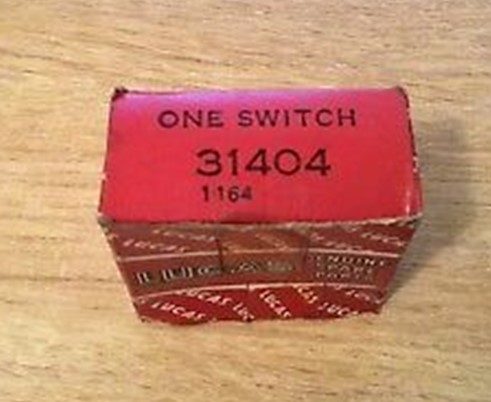
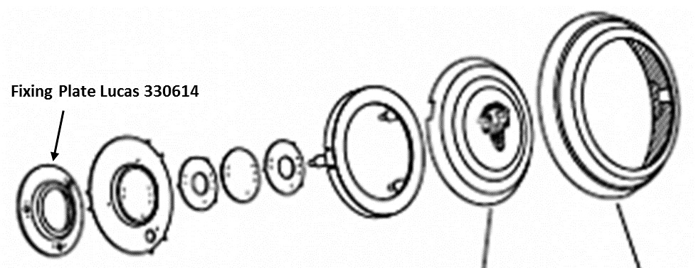
Radiomobile radios for Jaguar’s (1948 – 1961)
(Click pictures to enlarge)
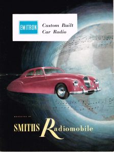
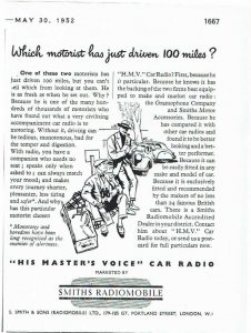 Early advertisements from 1949 to 1952
1. Introduction
After the war, Jaguar offered Radiomobile car radio systems as an “Optional Extra”. This article gives the history of the Radiomobile company and describes the radio systems fitted on Jaguar XK’s. As this survey started in the “pre-semiconductor” era, radio equipment used valves requiring a separate high voltage supply (over 200V!) placed in a box that was normally larger in size than the receiver unit itself. From about 1958 the first “transistorised” car radios appeared and miniaturization of equipment was about to start. We have to understand that these first transistor radios were in fact “hybrids” using a combination of valves and semi-conductors using a “semi-conductor” rectifier system and later some transistors.
We follow the development of the radios as used for the Jaguar XK 120, 140 and 150 over a period from 1949 till about 1961, but it is evident that the content also applies to contemporary Jaguar Saloon models.
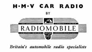
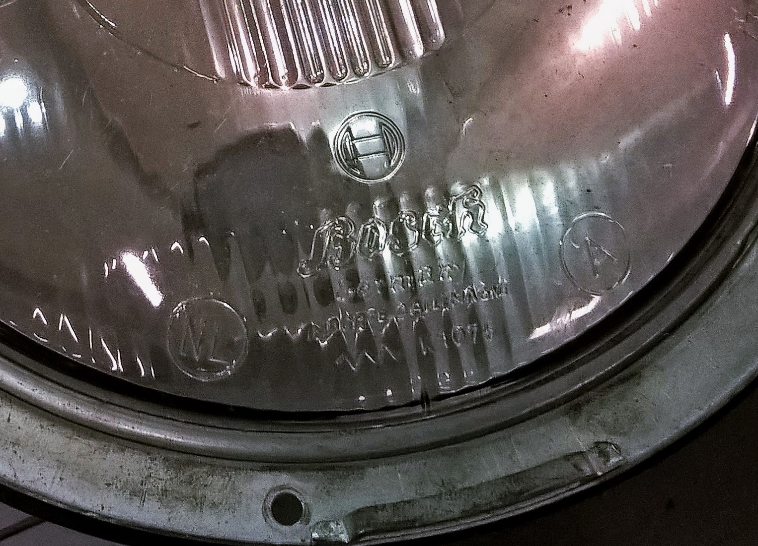
 The new official Radiomobile logo (left) showed the two parent companies HMV and Smiths Motor Accessories. The HMV logo (right) was shown on many Radiomobile models.
1.1 The Radiomobile company
Electric and Musical Industries (EMI) had been established in 1931 in the UK as the result of a merger between The Gramophone Company and The Columbia Graphophone Company. Next to recording and playing equipment, also radar and television were the outcome of extensive research activities within EMI. Radio manufacturing became one of their key businesses.
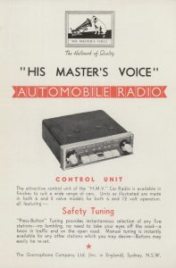
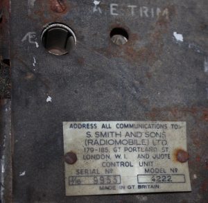
In 1945 EMI and Smiths Motor Accessories Ltd. established a new company named S. Smith and Sons Radiomobile Ltd. (with offices at Great Portland Street, London W1) essentially to sell car radios, initially manufactured and developed by The Gramophone Company, part of the EMI group.
 Compare the 1953 brochures for UK (left) and USA (right): HMV name and logo removed due the rights of RCA in the US. Pictures Roger Payne
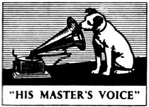
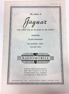
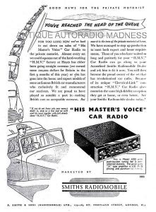
It was the intention of Radiomobile to use the His Master’s Voice brand name and call their radios HMV Car Radios and many radios therefore show the HMV name and/or emblem.
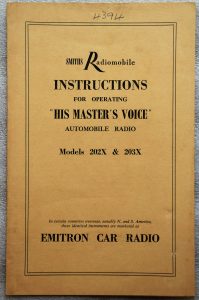
However, RCA in the USA still had the rights on the brand name His Master’s Voice for North and South America after they sold their share in EMI in 1935. It was thus not possible for Radiomobile to use the HMV brand name in the USA. Radiomobile radios fitted by Jaguar during production as an “Optional Extra” on cars destined for the USA were probably still branded as such with sometimes the HMV logo on the push-buttons. If a Radiomobile radio was fitted as an aftermarket product in the USA, these units were sold under the brand EMITRON. This brand name was owned and used by EMI for radio (component) exports to North & South America; EMITRON was also the brand name for radio valves and other electrical components manufactured by EMI and sold in the USA.
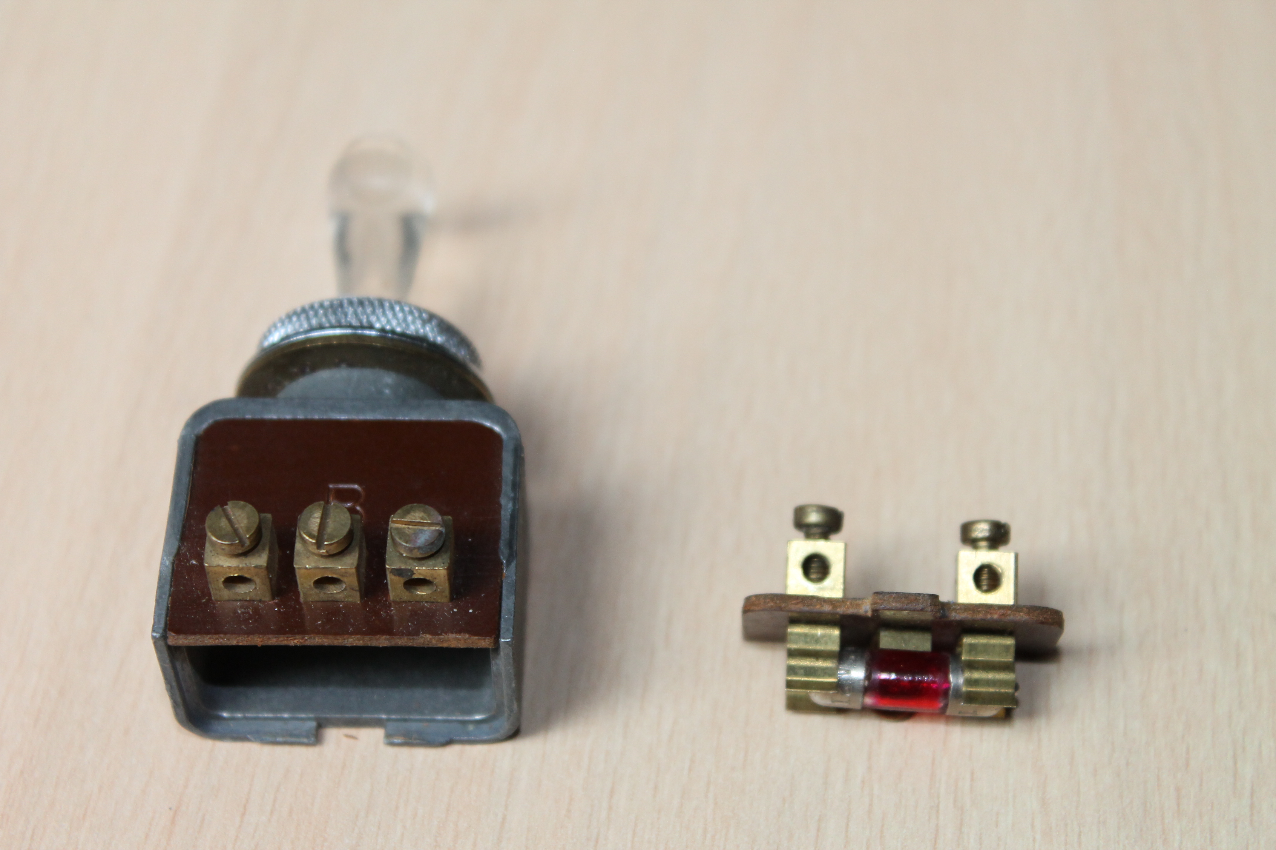
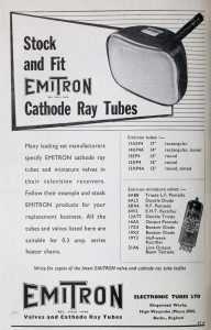 EMITRON as brand name for radio components
The official Smiths statement in their catalogues and brochures regarding this issue was: “In certain countries overseas, notably N. and S. America, these identical instruments are marketed as EMITRON CAR RADIO”. However, it seems that with the 1955 introduced 200 series the Emitron name had been dropped and all US destined versions were from now on Radiomobile branded, whereas in Europe (including UK) the two names (Radiomobile and His Master’s Voice) were used next to each other: the His Master’s Voice versions for the “high end” models only. The HMV brand name was eventually dropped in 1962 with the introduction of the 600 series, which only existed as a Radiomobile version throughout the world.
1.2 A survey of Radiomobile types from 1948 to 1961 as fitted on Jaguars
After the war the newly established Radiomobile company started the development and manufacturing of car radios. The following survey of 12 Volt Radiomobile car radios (using radio valves) should be seen as guidance only, as the precise dates of introduction of the various versions are often unknown, and radios still in stock may have been used in the Jaguar production of successor models. The application of models listed in Bold have been confirmed as “Optional Extras” in one or more Jaguar Spare Parts Catalogues.
- 1946 – 1951 100 Long & Medium Wave for Europe
- 1946 – 1951 101 Long & Medium Wave for Europe (no Tone Control)
- 1948 – 1951 4012 Medium Wave for N. & S. America and S. Europe
- 1948 – 1951 4014 Medium Wave for Australia & New Zealand
- 1949 – 1951 4050 Long & Medium & Short Wave for Rest of World
- 1951 – 1955 4100 Long & Medium Wave for Europe
- 1951 – 1955 4102 Long & Medium Wave for World excl. Europe
- 1951 – 1954 4200 Long & Medium Wave for Europe
- 1951 – 1954 4202 Long & Medium Wave for World excl. Europe
- 1953 – 1955 4260 Long & Medium Wave for Europe
- 1953 – 1955 4262 Long & Medium Wave for World excl. Europe
- 1953 – 1955 4263 As 4262 but 6 Volts
- 1953 – 1955 4300 Long & Medium & Short Wave for World excl. N.A. and Europe
- 1955 – 1958 200 X Long & Medium Wave for Europe
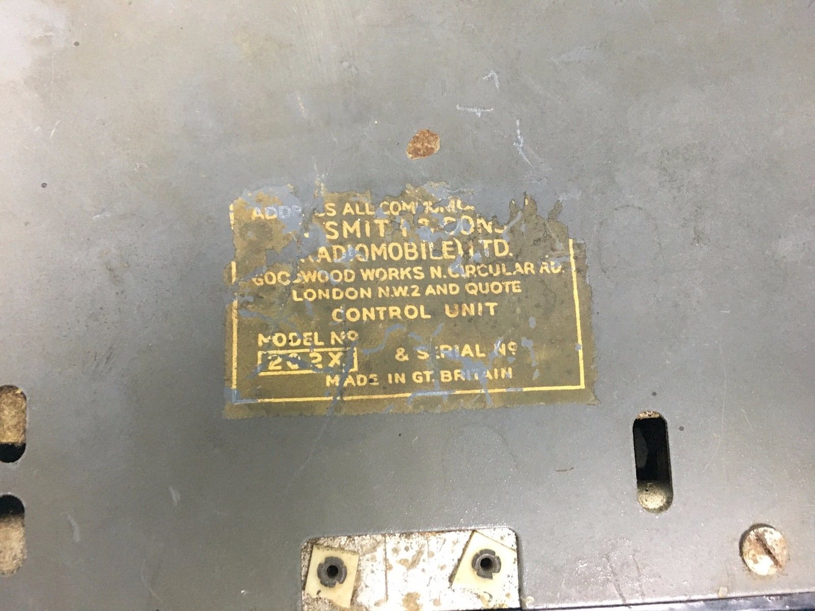
- 1955 – 1958 202 X Medium Wave for World excl. Europe
- 1955 – 1956 220 X Medium Wave for Europe
- 1955 – 1958 230 R Medium & Short Wave for World excl. N.A. and Europe
- 1956 – 1958 20 X Long & Medium Wave for Europe
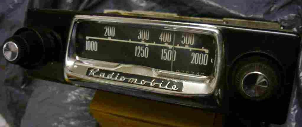
- 1956 – 1958 22 X Medium Wave for Europe
- 1959 – 1961 40T Long & Medium Wave for Europe
- 1959 – 1961 41T Long & Medium Wave for Europe; polarity switch
- 1959 – 1961 42T Medium Wave for World excl. Europe; polarity switch
- 1959 – 1961 42TC Medium Wave for World excl. Europe; polarity switch; tone control
- 1959 – 1961 400T Long & Medium Wave for Europe
- 1959 – 1961 401T Long & Medium Wave for Europe; polarity switch
- 1959 – 1961 402T Medium Wave for World excl. Europe; polarity switch
- 1960 – 1961 50T Long & Medium Wave for Europe
- 1960 – 1961 51T Long & Medium Wave for Europe; polarity switch
- 1960 – 1961 52T Medium Wave for World excl. Europe; polarity switch
- 1960 – 1961 52TC Medium Wave for World excl. Europe; polarity switch; tone control
- 1960 – 1961 500T Long & Medium Wave for Europe
- 1960 – 1961 501T Long & Medium Wave for Europe; polarity switch
- 1960 – 1961 502T Medium Wave for World excl. Europe; polarity switch
We occasionally see an original Jaguar with a Radiomobile radio that is not on the official list of “Optional Extras” as listed in the various SPC’s. Remember that Radiomobile radios were also supplied and installed by Jaguar dealers afterwards. We mention e.g. the Radiomobile Model 4100 on the XK 120 and the Model 20X models used on the XK 150, which both were of a simpler design and may have been installed by dealers to save cost. For the latter, these models have been even included in the “Smiths Radiomobile Installation Instructions” for the Jaguar XK150. We have therefore included the description of several Radiomobile radios not formally recommended by Jaguar in this article.
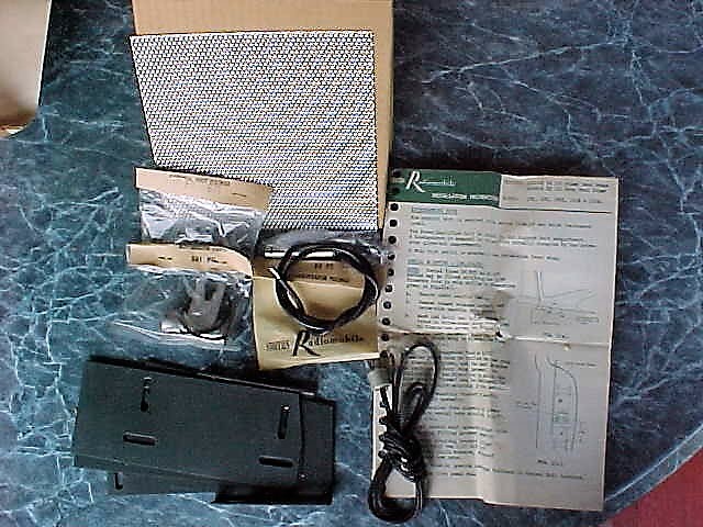
When a radio was fitted by the Jaguar factory, a Radiomobile Operating Instruction folder and the Radiomobile Warranty card were included which had the Jaguars body number written on it in pencil.
1.3 Manufacturing facilities
From the early Thirties onwards HMV radio production was centred at EMI’s Sheraton Works in Hayes, 15 miles to the west of London. Radiomobile production of (HMV) car radios started in the existing Smiths Cricklewood Works, London NW2, a vast industrial site built in the 1920’s and continuously extended in the decades thereafter, housing various Smiths industrial activities including “Motor Accessories”. However, there are indications that the first HMV/Radiomobile car radios (100 series) have still been produced at Hayes.
The Cricklewood Works housed next to the Motor Accessories division three other Smiths activities: Industrial Instruments, Aircraft Instruments and the (well known) English Clocks production.
From about 1952 the production of car radios gradually moved to the new Smiths Goodwood Works, North Circular Road (Staples Corner) in London NW2, not far from the Cricklewood Works. The export division of Radiomobile stayed at Cricklewood, as we may conclude from various brochures.
2. Radio installations offered for the XK 120
2.1 Available “optional extras”
The following radios of the above listing were available for the XK 120 either as an “Optional Extras” over the period 1949–1954 or as a “dealer option”. The “Optional Extras” as listed by Jaguar have been indicated in Bold letters.
- Model 100 with Long and Medium Wave and Tone Control
- Model 101 with Long and Medium Wave, without Tone Control
- Model 4012 with Medium Wave for North and South America
- Model 4014 with Medium Wave for Australia and New Zealand
- Model 4050 with Medium and Short Wave
- Model 4100 with Long and Medium Wave
- Model 4102 with Medium Wave
- Model 4200 with Long and Medium Wave
- Model 4202 with Medium Wave
- Model 4300 with Long, Medium and Short Wave
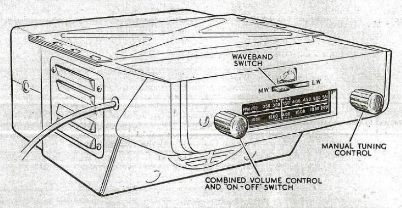
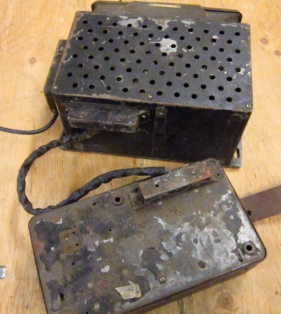
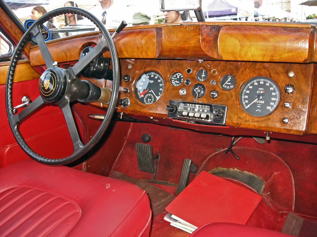
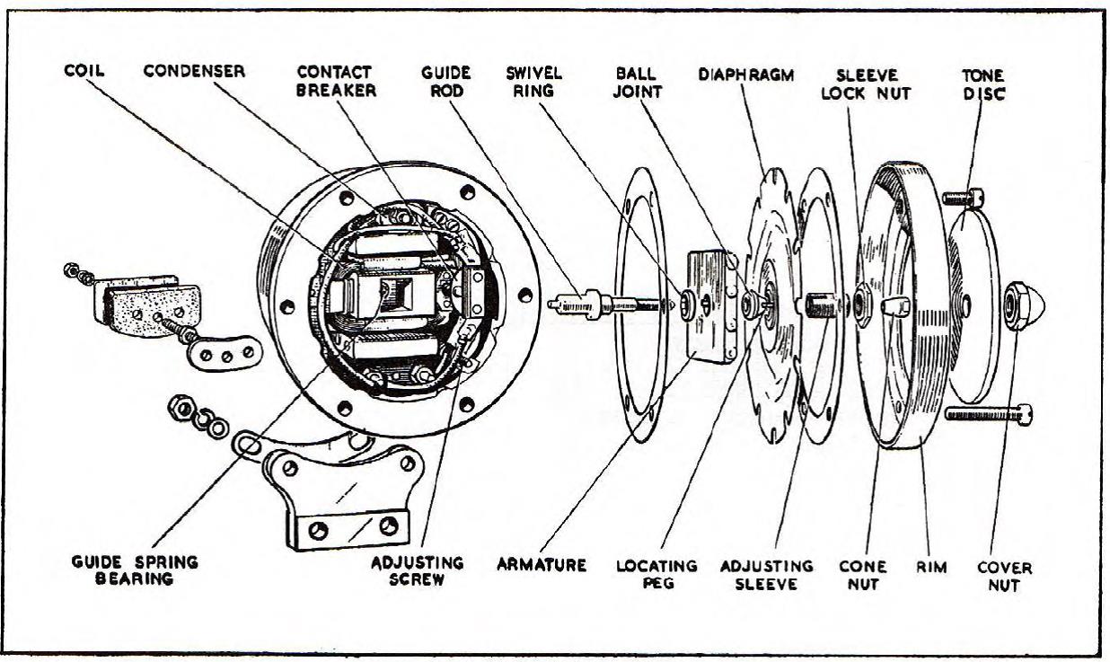
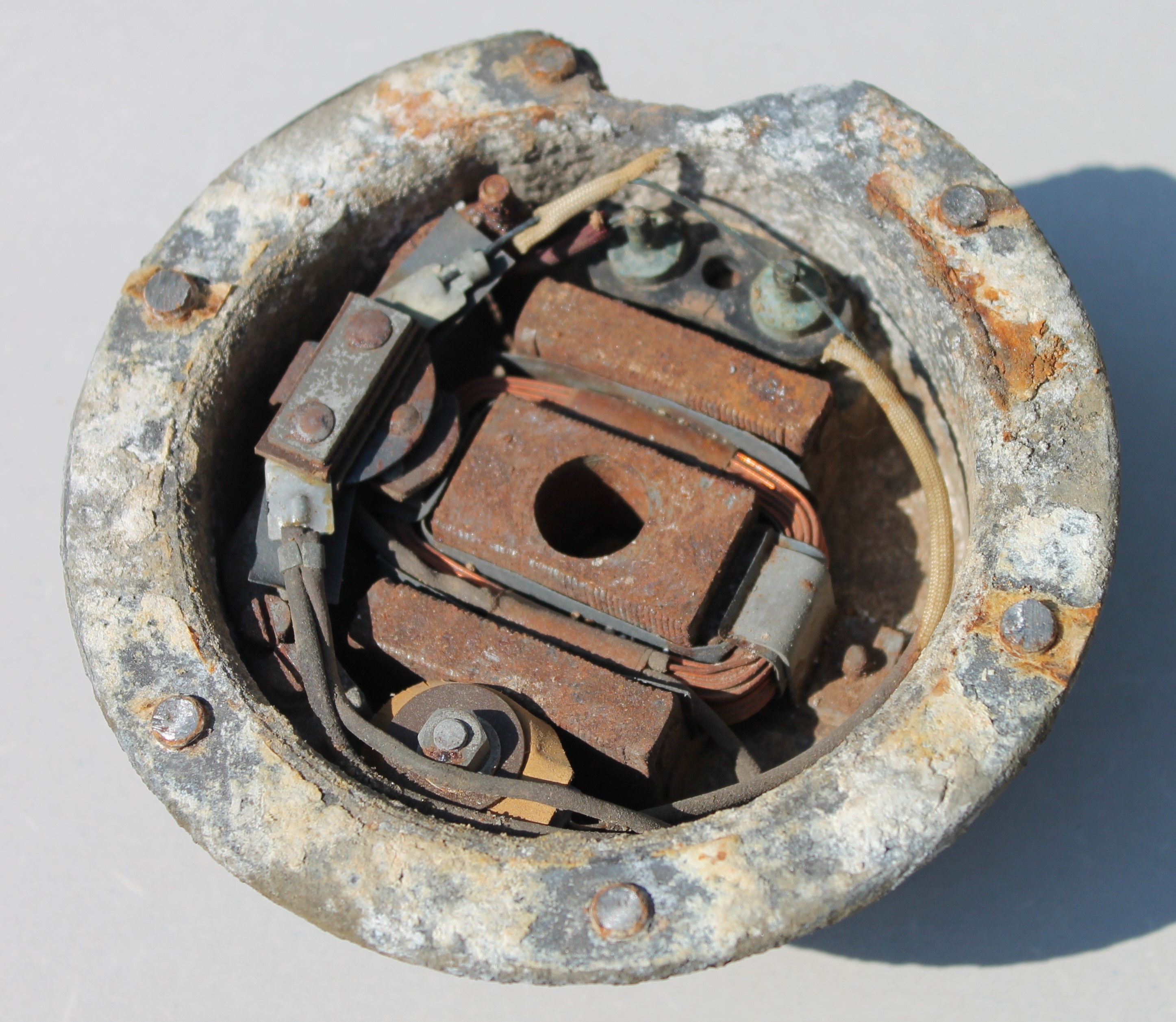
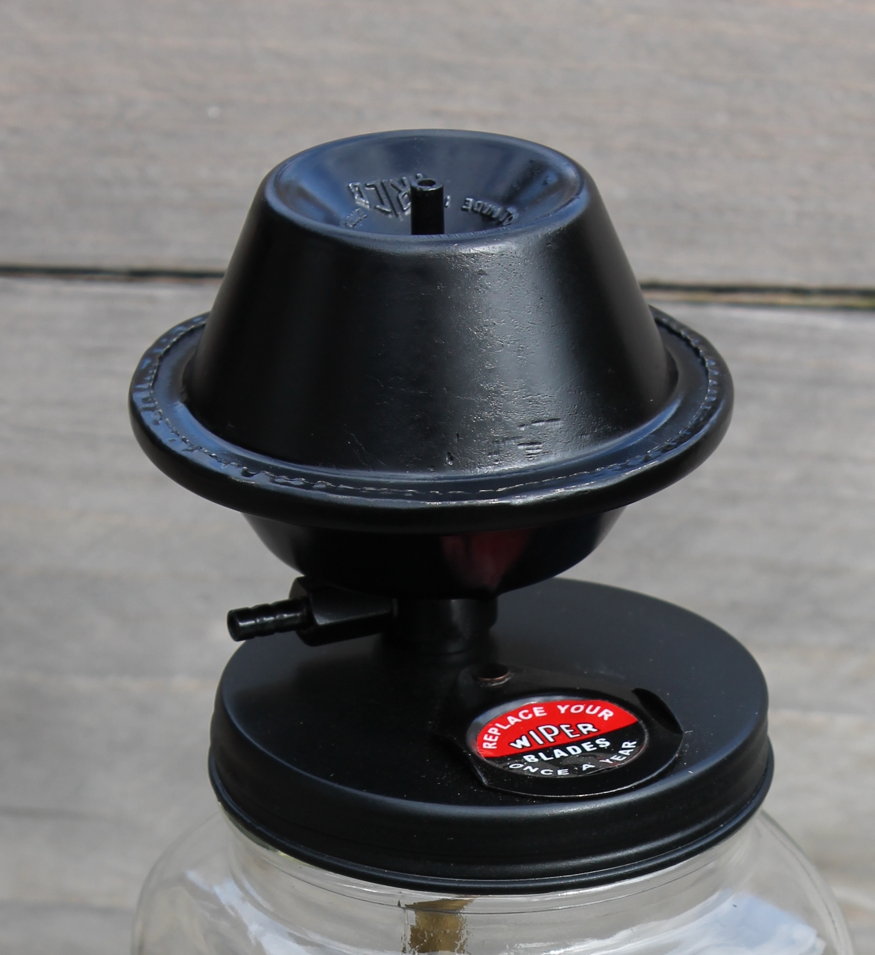
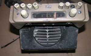
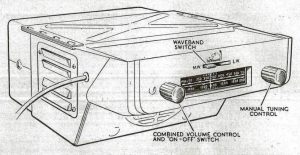
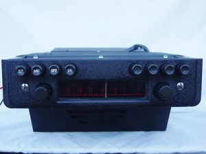
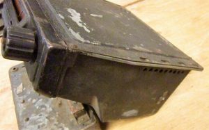
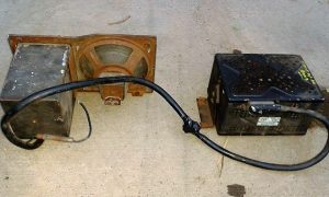
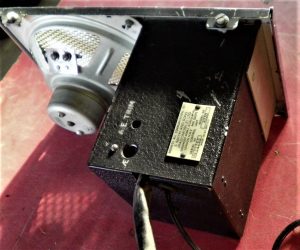
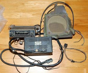
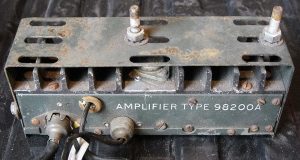
Note that the 100 and 4000 series both had a “single unit” construction consisting of a receiver (also called controller), a loudspeaker and a power supply (or amplifier) although the latter could be detached. Later generations starting with the 4100 / 4200 / 4300 series, were of the “3 unit” construction” (or also called the “Electrical Link” construction by Radiomobile): receiver in/under the dashboard and both speaker and amplifier remotely positioned either in the front or the rear of the car all connected (“linked”) via electrical cables.
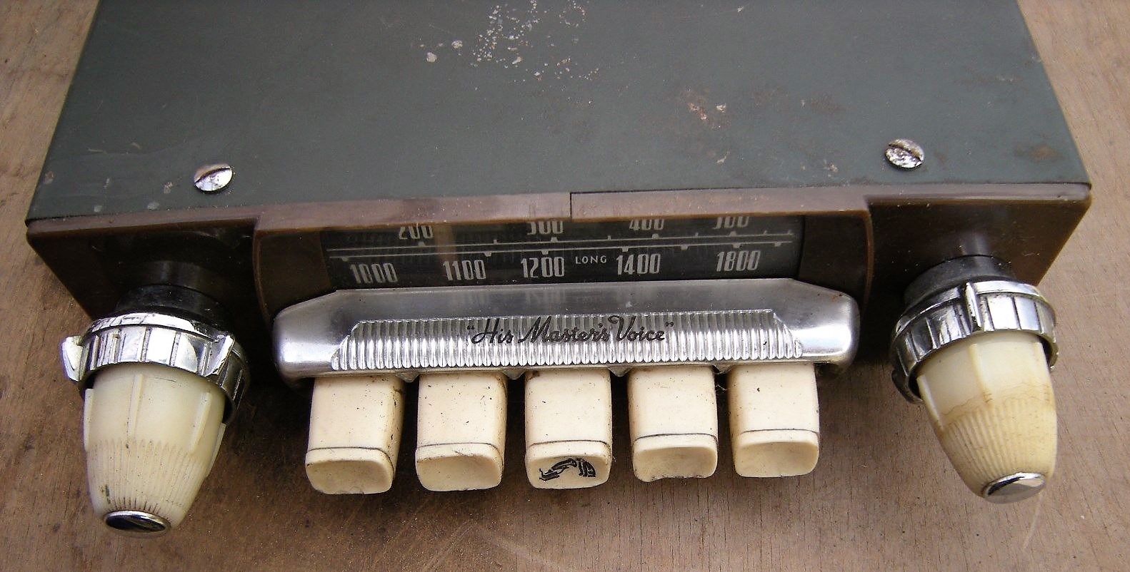
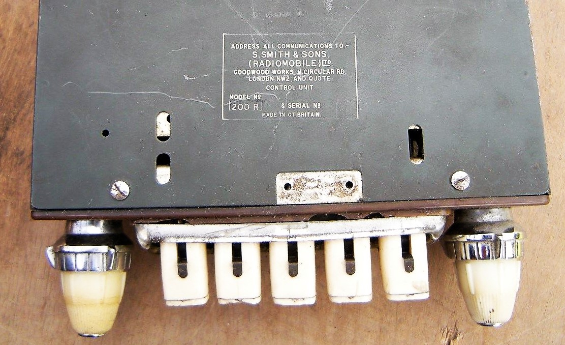
2.2 Model 100 (1948 – 1951)
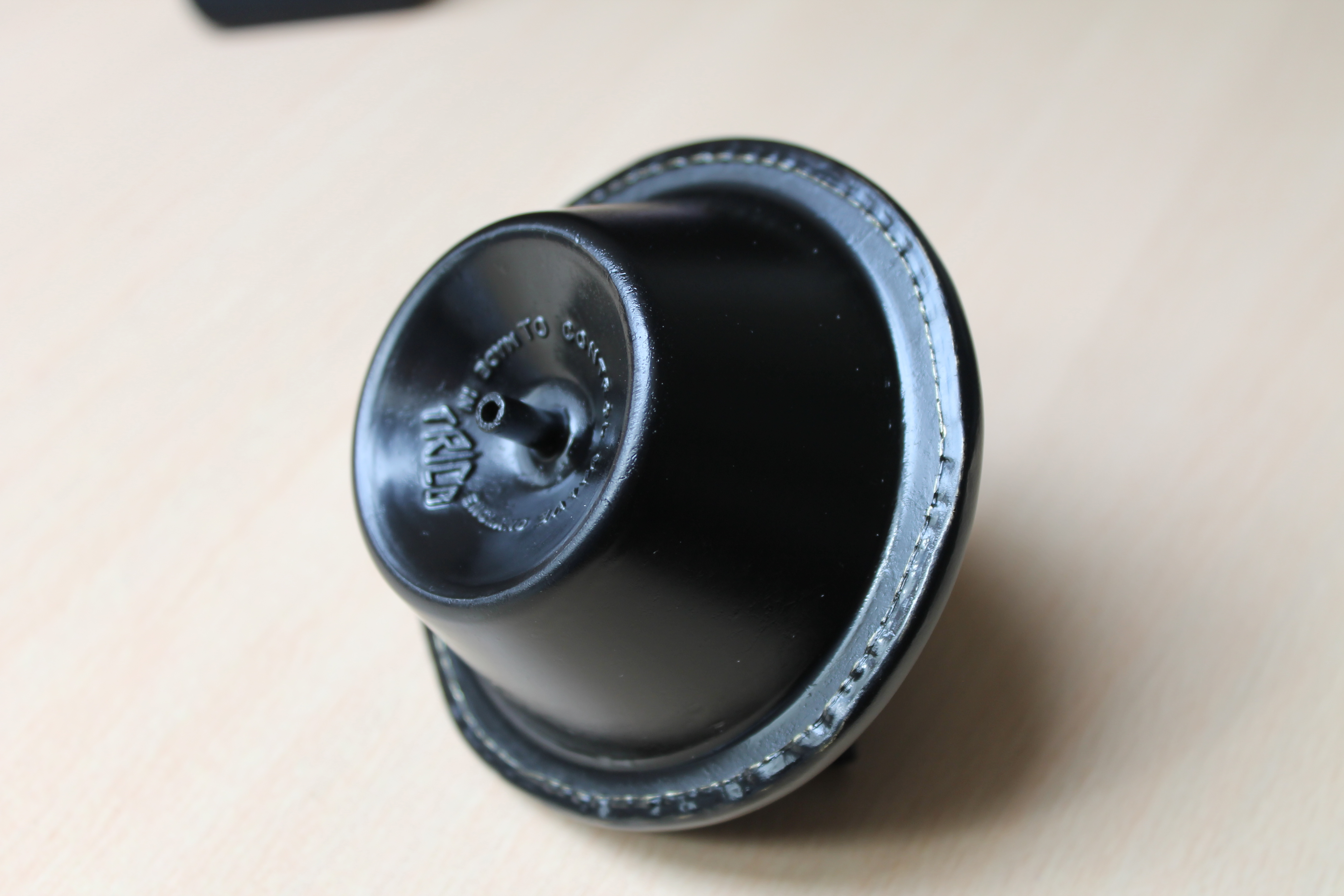
The first Radiomobile car radio was named Model 100 (manufactured from 1946-1951) and Jaguar initially used it from 1946 to 1948 in the 1½, 2½ and 3½ Litre Saloons. The Model 100 was only installed (as an option) on the OTS version of the XK 120. This Medium and Long Wave receiver was of the “single unit” construction. It received Jaguar part number C.4600. At the back of the receiver an amplifier unit was mounted (part number C.4601; Radiomobile code unknown) and connected via an external cable. The power output of this radio was 3.5 Watts and the 5” loudspeaker had an impedance of 5 Ohms. Normally the 100 was delivered in black (example shown below) but other colours for the front (escutcheon) were possible.
 Model 100 with its typical “single unit” construction, but the Amplifier at the back could be detached
Radiomobile supplied various colour combinations to the car industry to match e.g. the dashboard design. Radiomobile provided Bentley even with a wooden facia and a different scale. Note that the Jaguar versions for the 100 series were black (front and knobs) while other car manufacturers may have opted for other colours, knobs and scales.

 Bentley with wooden front Grey front and white knobs Beige front and white knobs
Radiomobile started to export these models throughout Europe in the early 1950’s.
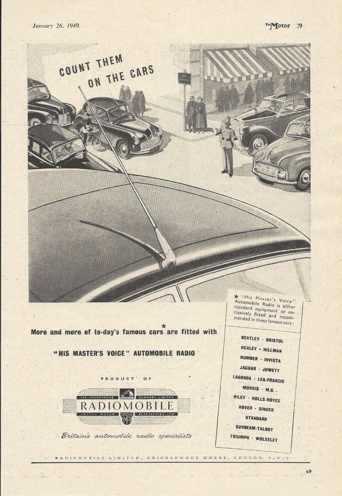
 October 1948 Radiomobile advertisement for Jaguar Export: Belgian advertisement of RM 100
Model 101 was identical to the 100 but was supplied without Tone control and pre-set push buttons. This version was not in the Jaguar “Optional Extras” programme, but may have been installed by Jaguar dealers.
 Model 101 without Tone Control
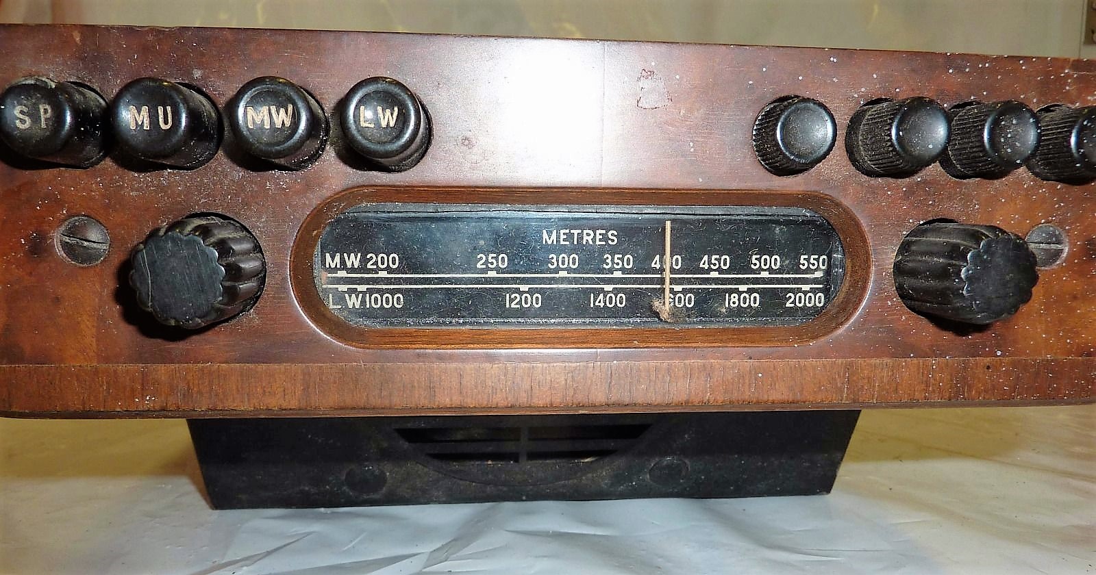
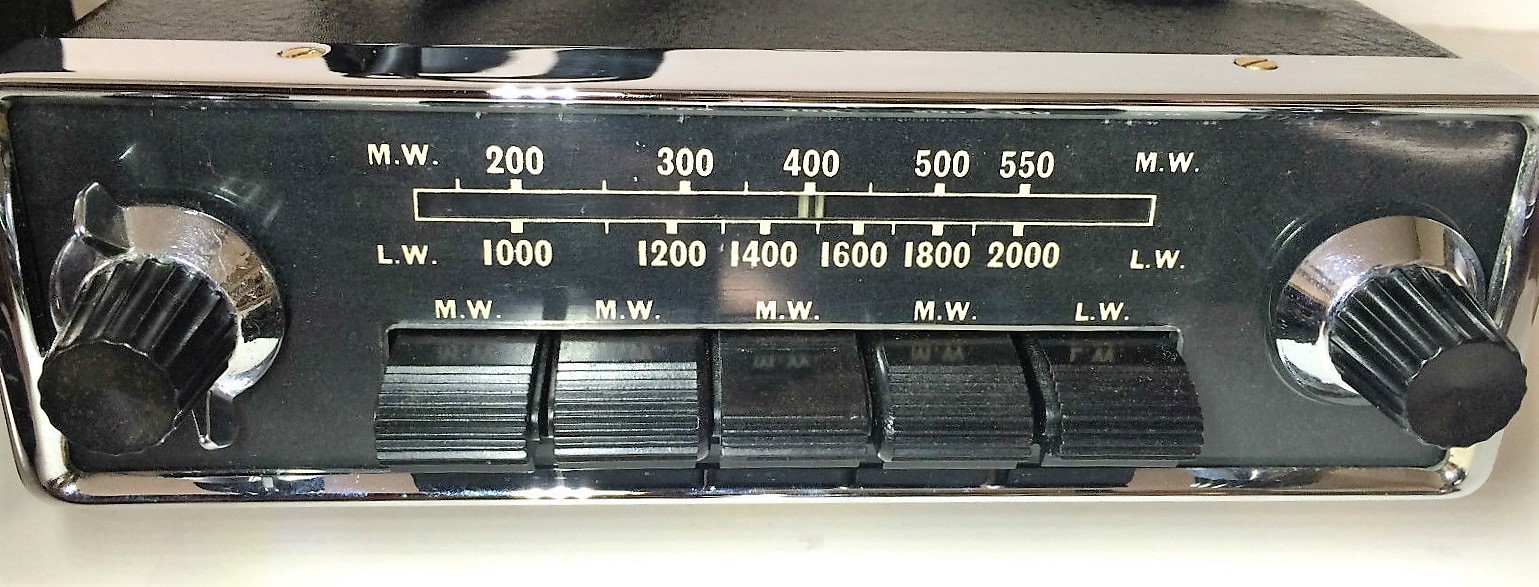
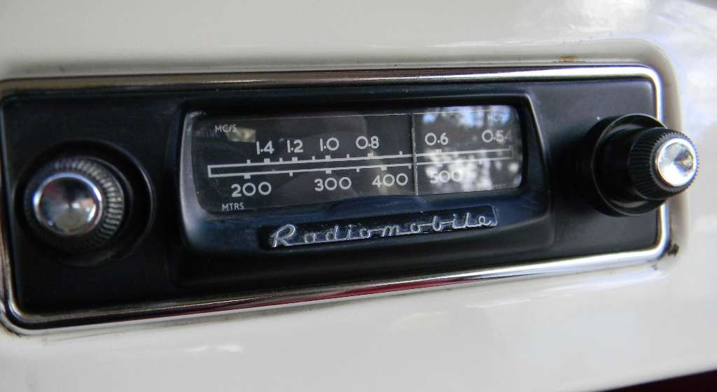
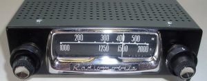
The 100 series were used in most European countries. Medium Wave radios in 1950’s Europe had a scale running from 200 to 550 metres and a Long Wave scale from 1000 to 2000 metres.
2.3 Model 4012 & 4014 (1948 – 1951)
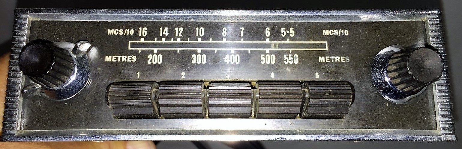
The Model 4012 with Medium Wave was used on the OTS version of the XK 120 in North and South America and some Southern European countries. Whereas in Europe the Medium Wave frequency spectrum had been defined starting from 531 kHz to 1600 kHz, in North America the upper limit run up to 1700 kHz. The radio on the photo below has the MW scale in MHz/10 (instead of metres), running from 16 to 6 so it may still have been a European version. The 4012 used the same power unit as the Model 100 radio and had Jaguar part number C.4608.
 Radiomobile 4012 with MW only
The Model 4014 (Jaguar part number C.4609) with Medium Wave was only used in Australia and New Zealand. In Australia MW radio broadcast allocation was from about 1700 kHz to 535 kHz. Note that radios sold in Australia normally had a special dial face per state with local radio station-codes printed on it.
2.4 Model 4050 (1949 – 1951)
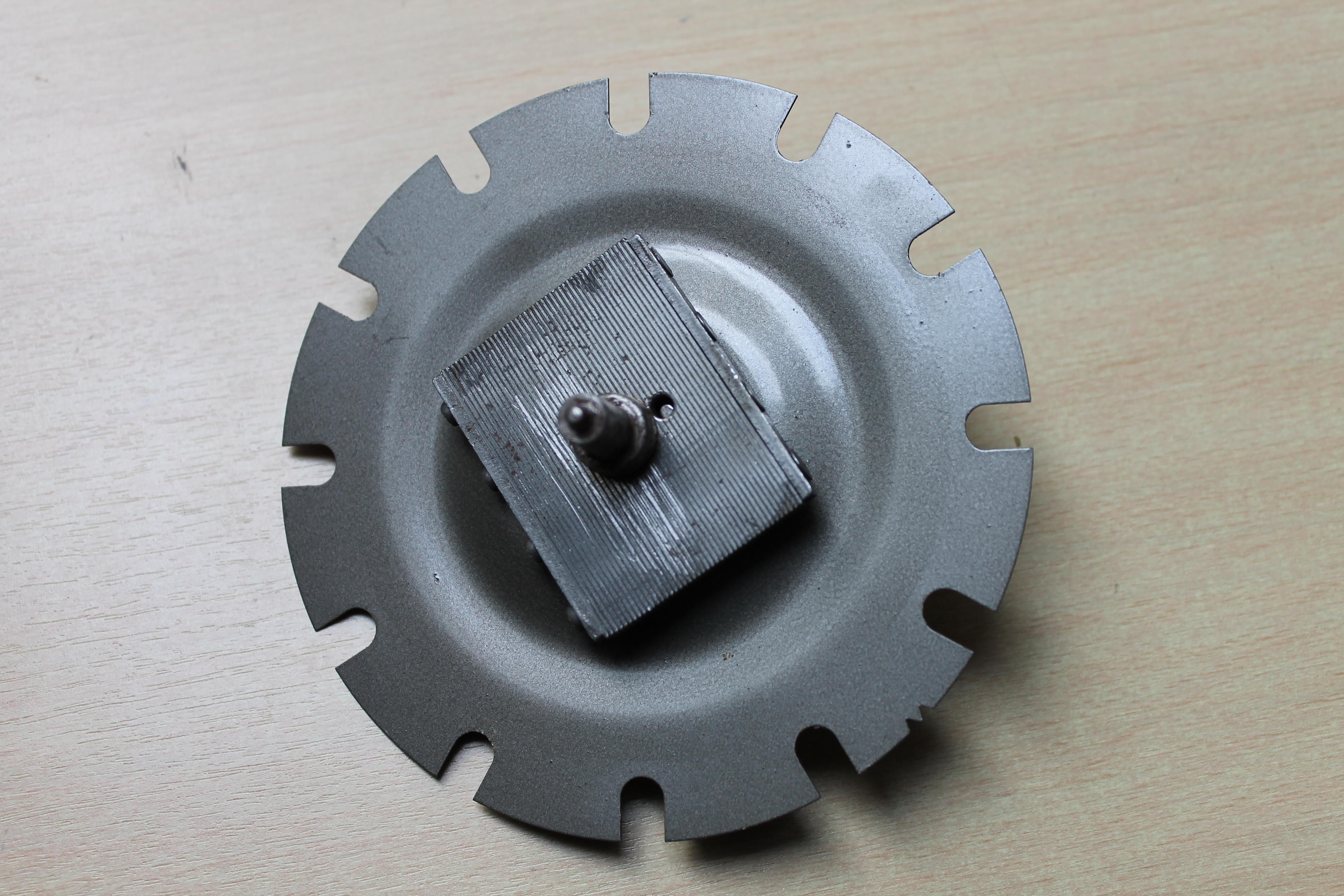
In the autumn of 1949 Radiomobile introduced its first car radio with Short Wave, in addition to Medium Wave. There were 7 Short Wave bands, each with a separate indication on a drum-type tuning scale.
Although part of the “single unit” construction range (like the Model 100) the front of the 4050 was clearly different. It had 4 push buttons (to pre-select Medium Wave stations) positioned below the scale. The “Tone-Control” was done by one turning knob with 4 positions instead of the two tone-control push buttons of the Model 100 version. Apparently the 4050 had the possibility to install a remote speaker.
Model 4050 (Jaguar part number C.4610) was destined for many countries but not for the main markets such as Northern America and Europe and only used on the OTS model of the XK120 (and other contemporary Saloons). Note that the 4012, 4014 and 4050 have sequential Jaguar part numbers.

 The rare Model 4050 model with 4 push buttons Side view of receiver
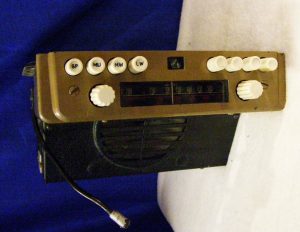
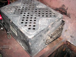
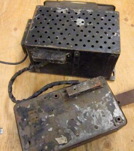 Complete set with receiver (top) and amplifier (bottom)
2.5 Installing the 100 and the 4000 series
If an optional radio had been ordered, Jaguar removed the map drawer of the DHC or FHC version and the radio tuner was installed in its place using special brackets. On the earlier XK 120 DHC/FHC models the wood panel opening had to be widened but cars produced after 31st December 1951 were made with the correct width for the radio receiver: 2 x 7 inch (51 x 178 mm) typically. Remember that the aforementioned versions for the XK 120 OTS were all of the “single unit” construction.
Radiomobile provided instruction booklets for the installation of car radios. For the 1951 successor models (see next chapter) specific instructions are available for the XK 120 models. Instructions do exist for the “Jaguar Mark V 1950-1951 Saloon and Coupe models“, published in May 1951, possibly covering the RM100 and 4000 series. In addition, there is one for “Jaguar Mark VII 1951 models“, published June 1951. (Information: Roger Payne).
Fitting a Model 100 under the dashboard of an early Saloon(left) and an Austin 12/16 (right) where the amplifier unit has been decoupled and is positioned above the receiver. Note: roof aerial for both cars!
2.6 The 4100 series (1951 – 1955)
Although not part of the “Optional Extras” list of Jaguar, the 4100 series can still be found on Jaguars as it was around 25% “less costly” than the 4200 series and (apparently) offered by Jaguar dealers. It was produced in parallel to the 4200 / 4260 models and may therefore have been used on early XK 140’s as well. Radiomobile referred to the series as having “High Sensitivity” whereas the 4200 and 4300 series had “Super Sensitivity”.
The Model 4100 had LW and MW reception, but only 3 push-buttons instead of the 5 buttons of the 4200 series. It used the same Amplifier Unit as used for the 4200 and 4260 series: only the low power 46028A version was recommended for this receiver. For more information, see paragraph 2.9.
Another version in the 4100 series was the Model 4102, similar to above but with MW only. US Jaguars may have had this particular version installed (branded as Emitron 4102) as LW radio wasn’t required in the USA.
 Radiomobile Model 4100 in black. The HMV logo is missing on centre button. Model 4100 in an XK 120.
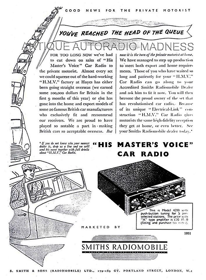
2.7 Model 4200 & 4202 (1951 – 1954)
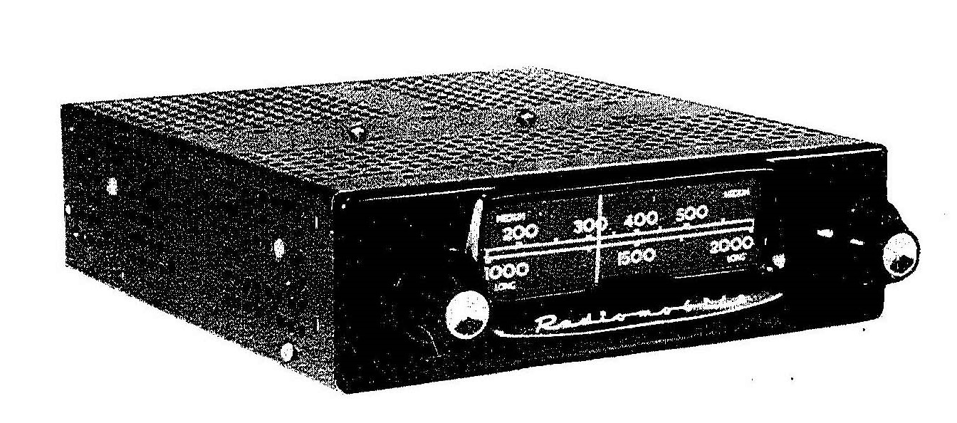
In July 1951, an improved version of the Radiomobile 100 and 4000 series became available: the 4200 series. This range was used from 1951 till about 1954. Models that have been offered on the XK 120 are the Model 4200 and Model 4202, introduced on the FHC models in 1951. At the same time the OTS got this radio option replacing the older types and it was also available on the DHC from 1953 onwards.
Model 4200 (with Jaguar part number C.5363) was a Long and Medium Wave receiver, in fact replacing the Model 100 version. It was the first of the “3-unit construction” replacing the “single unit” of the 100 and 4000 series. It had 5 push buttons: 4 for pre-selected MW stations and 1 for selecting the LW band. The face was black with a chromed rim and knobs available in various choices. This “standard” version is shown here below.
 Two examples of Model HMV 4200
The total power output of the radio system could be increased by opting for a “heavier” Amplifier. Radiomobile offered 2 versions: A-type and B-type of which the latter version was recommended and used by Jaguar. The complete car radio is therefore sometimes referred to as Model 4200B.
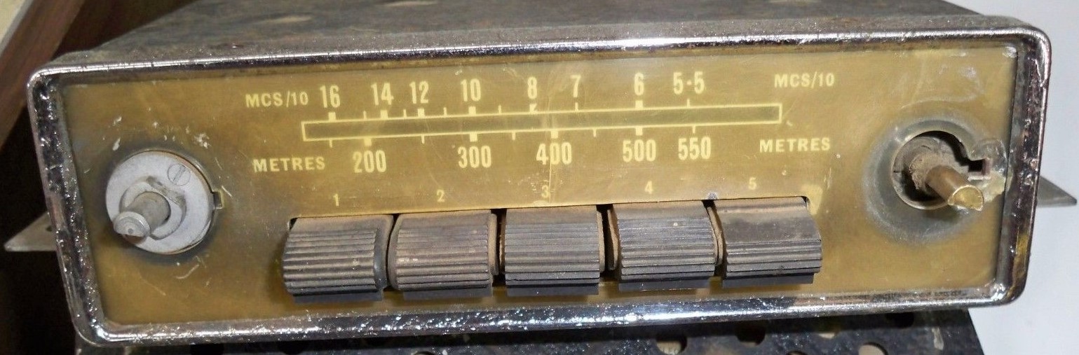
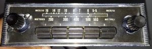
Model 4202 (Jaguar part number C.5370) was a simpler version of Model 4200 with Medium Wave only. Note that the scale is in Metres and MCS/10. Compare the 4202 front below with that of the 4200 shown above. This version was only available in 1952-1953. The Emitron 4202 version for America was manufactured in a dedicated Jaguar version with the text “EMITRON JAGUAR CUSTOM” instead of the scale indication in Metres (which seems logical for the USA). See also “Original Jaguar XK” by Philip Porter, page 65 of the 2003 edition.
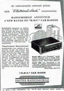
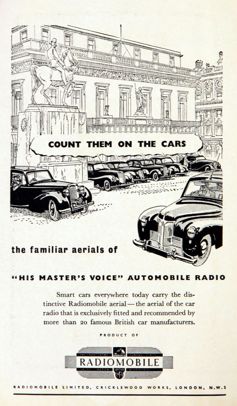
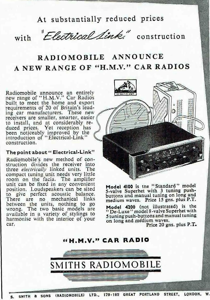
 Smiths Radiomobile 1951 and 1952 advertisements introducing the first radios of a “3-unit” construction

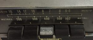 Model HMV 4202 in black Different front Model Emitron 4202
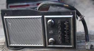
2.8 Radiomobile Model 4220 & 4222
Radiomobile also made ‘brand specific models” on basis of the 4200 series. Model 4220 is such an example, specially made for the Rover P4. The receiver part was positioned vertically and the loudspeaker was placed next to the receiver positioned behind gauze, while the (standard) remote amplifier was connected via a cable with connector plugs. The 4220 series has been derived from the 4200 series,
There were (at least) two versions: Model 4220 with MW and LW and Model 4222 with MW only. Both used the Amplifiers of the 4200 series (see 2.10)
 Typical arrangement of the 4220 series
 Model 4220 with MW & LW
 Model 4222 with MW only
2.9 Radiomobile Model 4300 with Long, Medium and Short Wave reception (1954 – 1955)
Although listed for the XK 120 in the Spare Parts Catalogue this radio was in fact more used on the XK 140 and therefore further detailed in chapter 3.
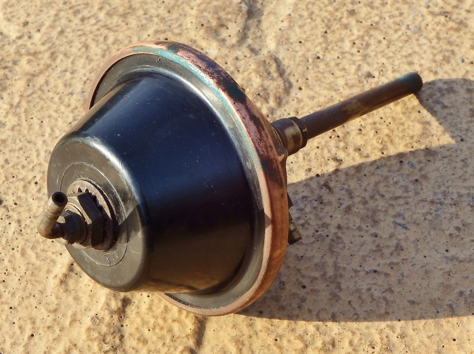
2.10 Amplifier units for the 4200 series
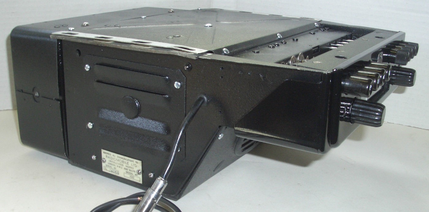
The 4200 series radios had a separate, remote Amplifier unit. There were two different versions of the Amplifier unit:
- Medium output version Type A with nominal 2.5 and maximum 3 Watt output for one loudspeaker
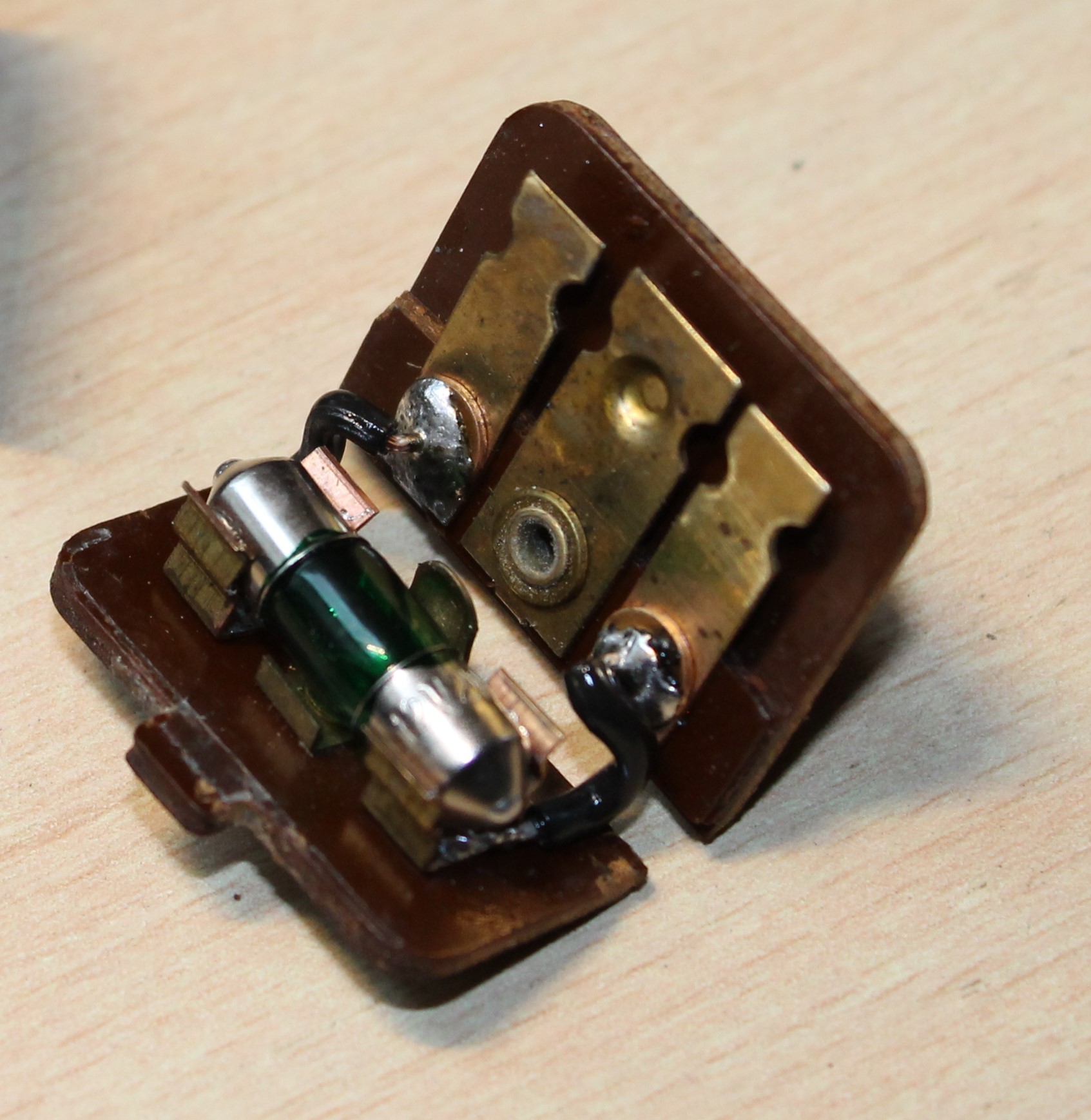
- High output version Type B with nominal 6 and maximum 7 Watt output, suitable for one or two loudspeakers.
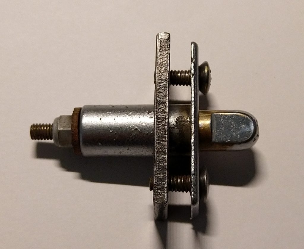
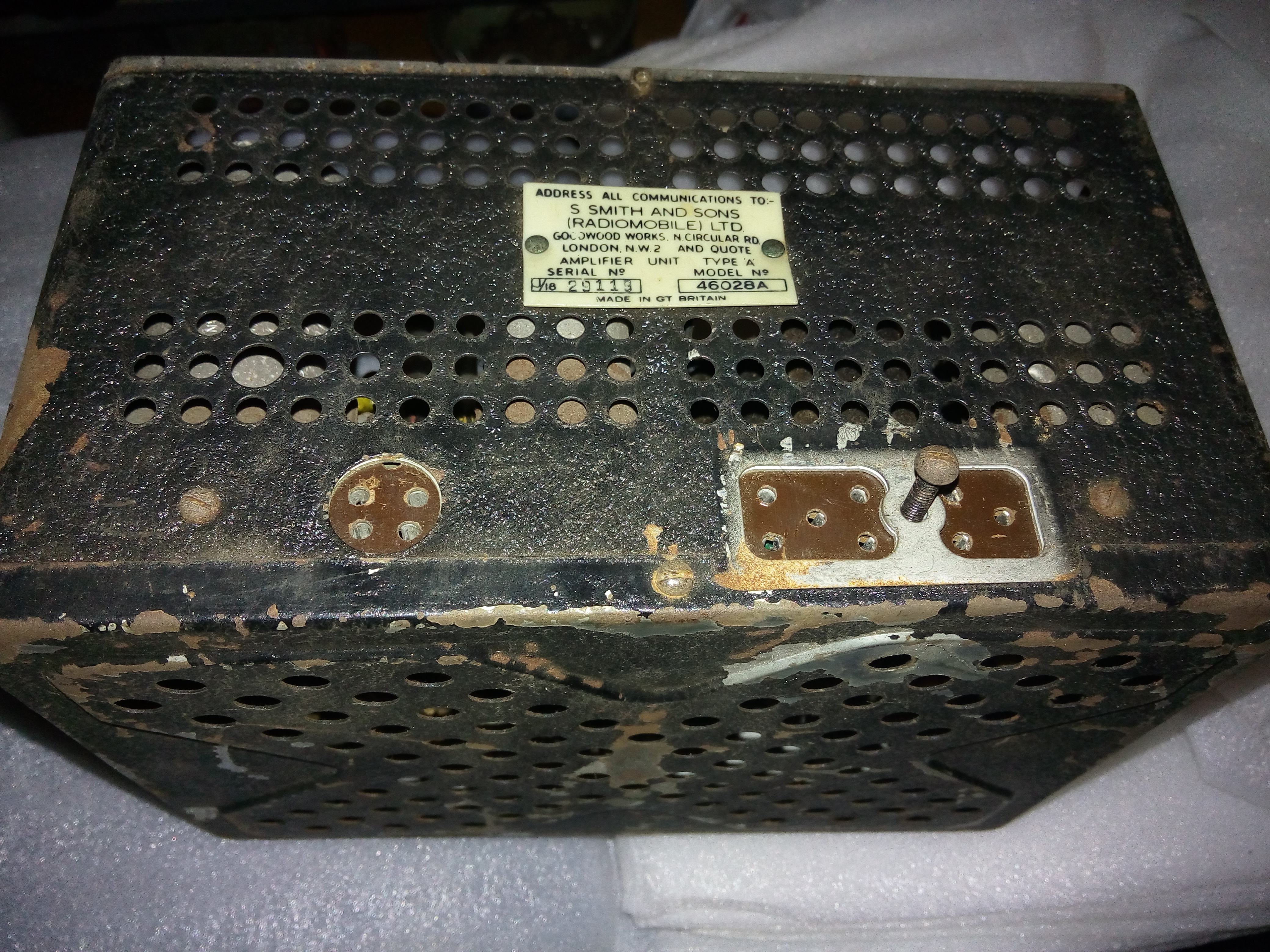
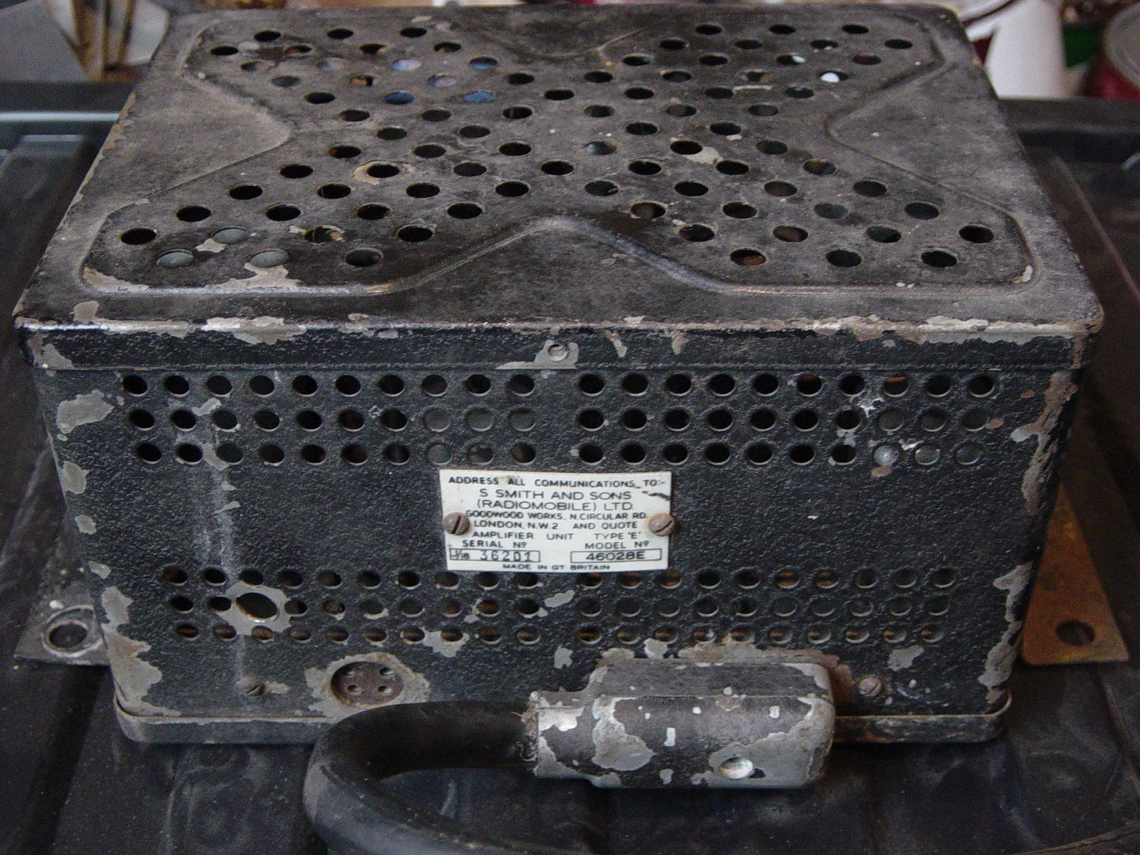
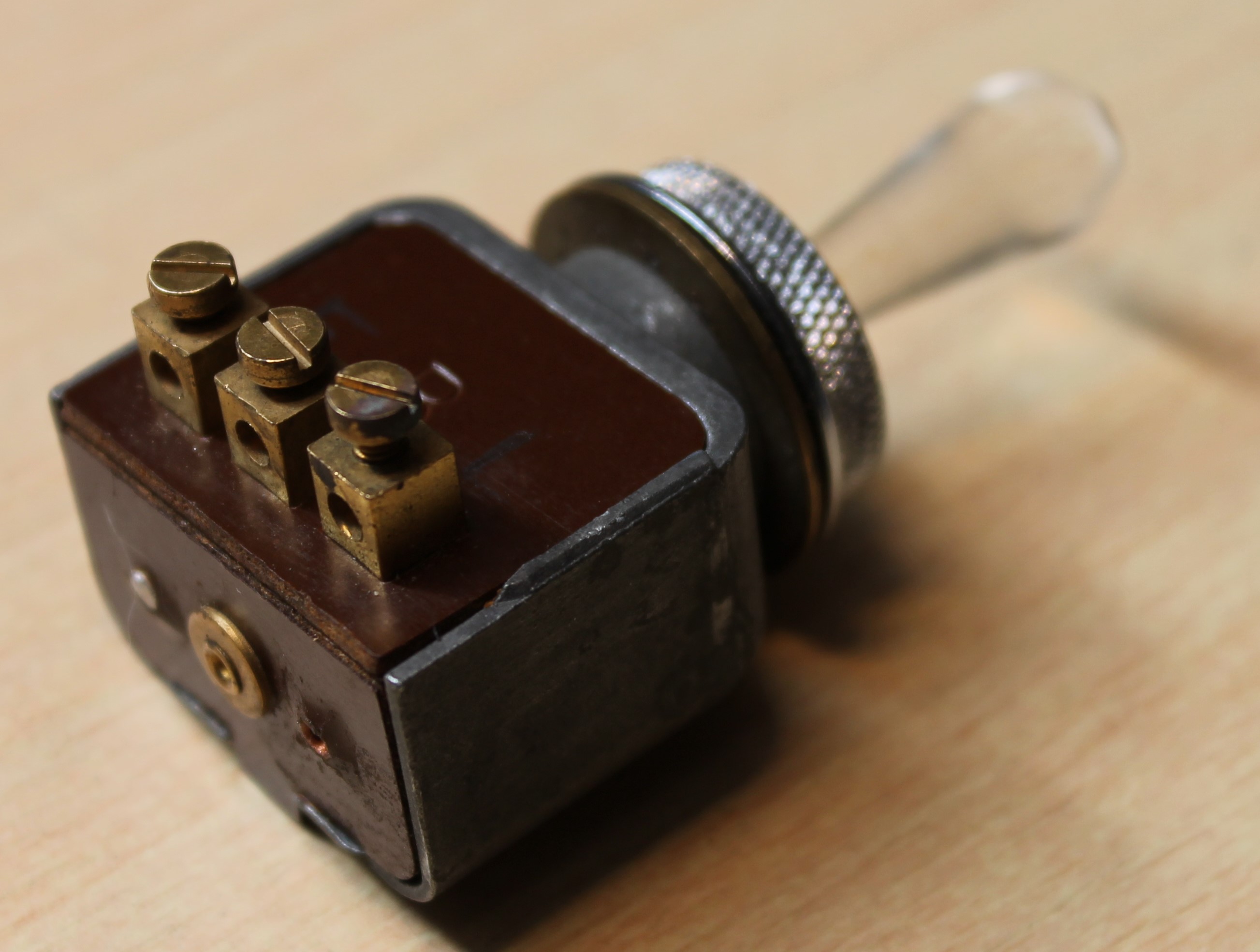
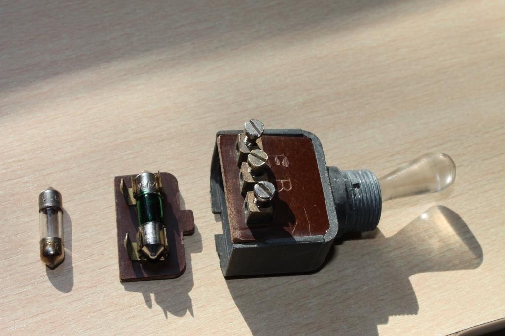
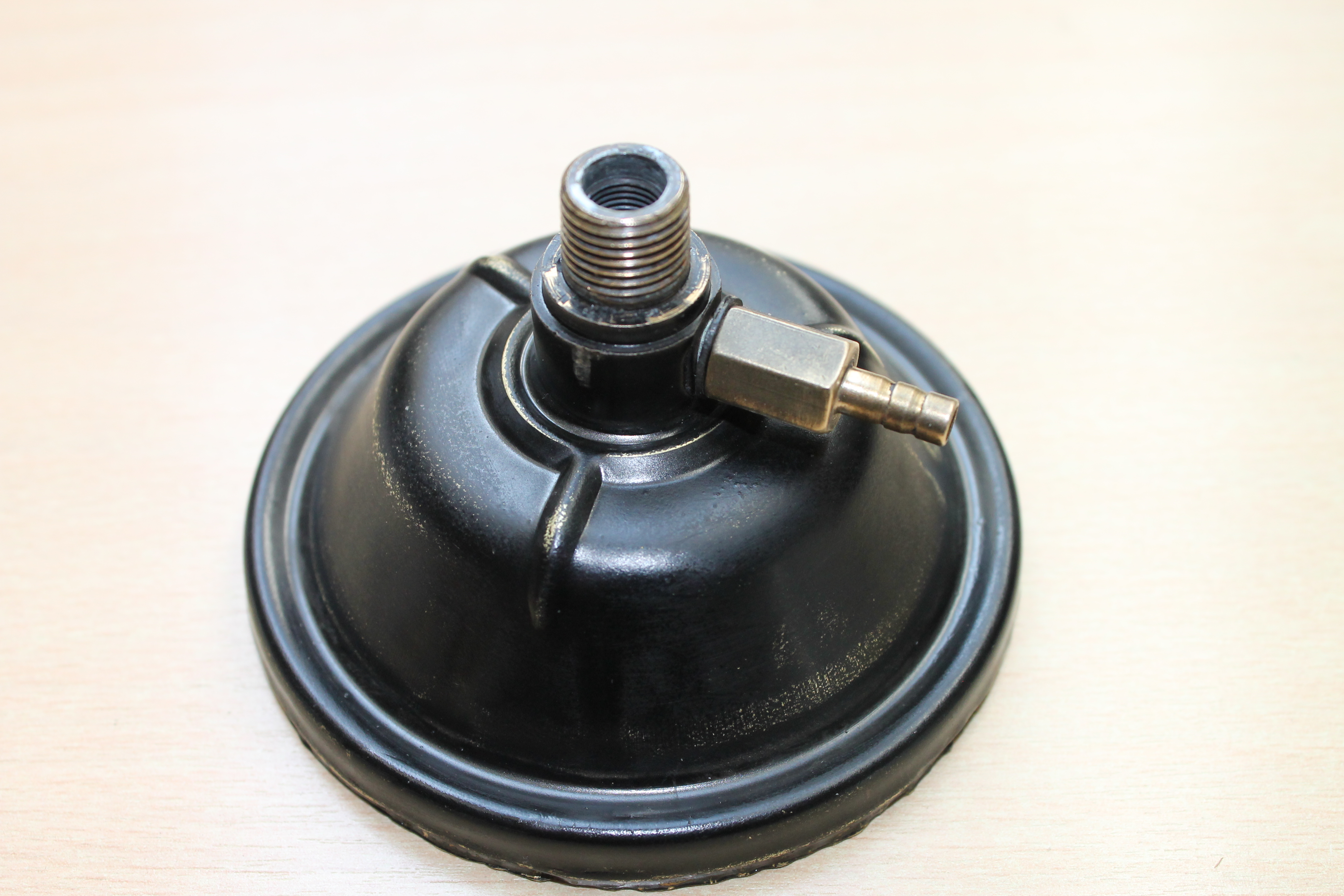
Radiomobile numbers are 46028A and 46028B respectively. There is also a Type E amplifier (coded 46028E) of which the exact application is unclear. Note that Jaguar only used the 46028B version with their part number C.5364.
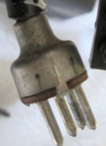
 An 8 pin connector cable was used for 46028 Amplifier units.
The first generation Amplifier Units had an 8-pin connector system for the cable from Receiver to Amplifier. This system was used for all “3 unit constructions” up to 1955. As we will see in Chapter 3, later generations “3 unit constructions” used a 5-pin connector system and the two generations are therefore not interchangeable! The loudspeaker connection of the first generation used a 4-pin connector and cable; the second generation had a 3-pin system.
2.11 Installing the 4200 series
A small 8-page booklet was published by Radiomobile in January 1952 giving detailed “Installation Instructions for His Masters Voice Automobile Radio Models 4200-4202 Series Smiths Radiomobile“. An instruction booklet exists specifically for the “Jaguar XK 120 Sports 1951 and 1952 Models“. Remember that the XK120 FHC had only been introduced around July 1951.
As mentioned before, early XK 120’s required widening of the drawer opening in the wooden dashboard to mount the Receiver unit. Cars produced after 31st December 1951 have the correct opening dimensions.
The 4200 series were the first of the “3-unit construction” generations and rather different from the previous 100 and 4000 series.
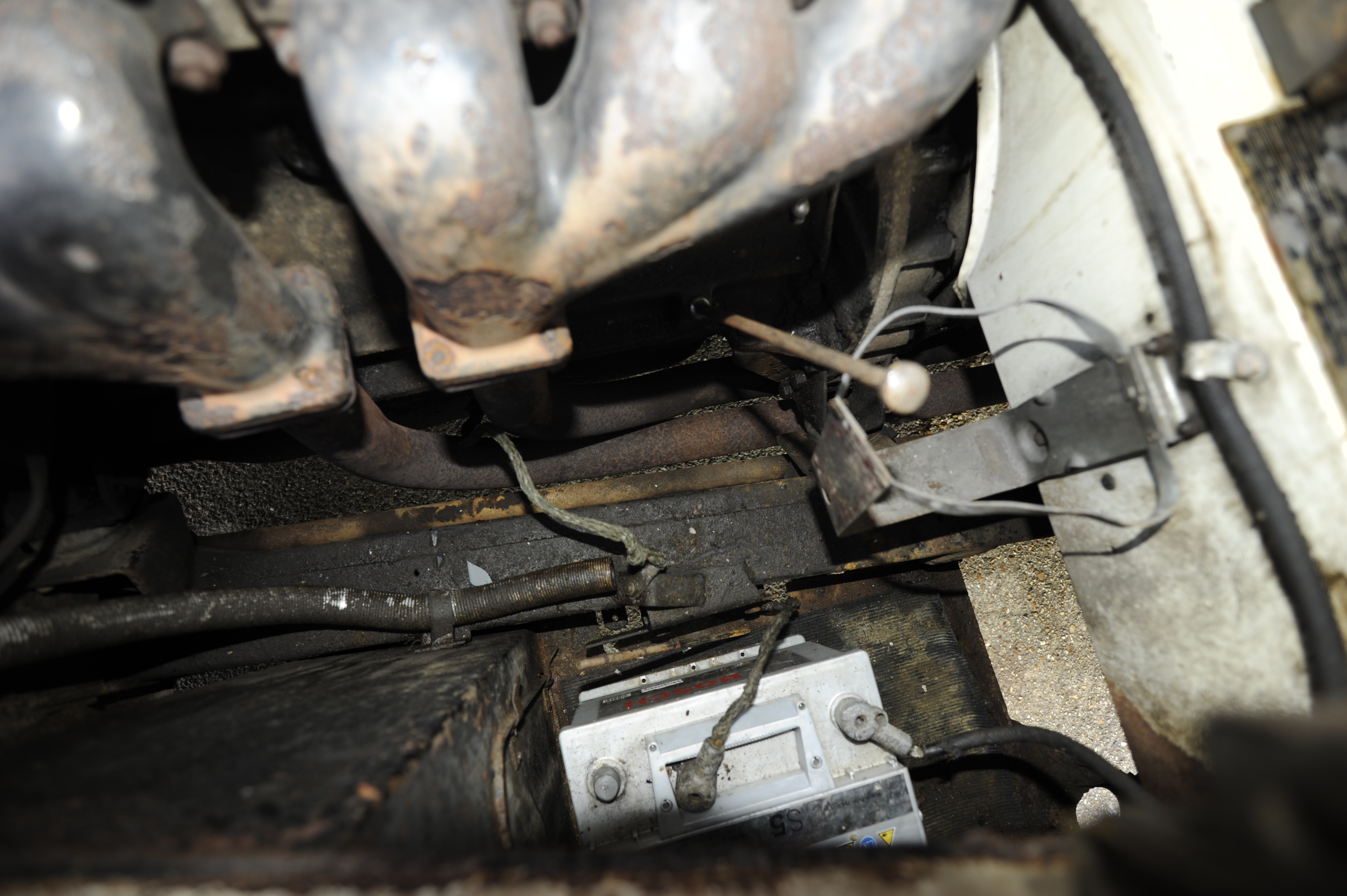
 Original 1954 amplifier installation between the Batteries
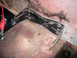
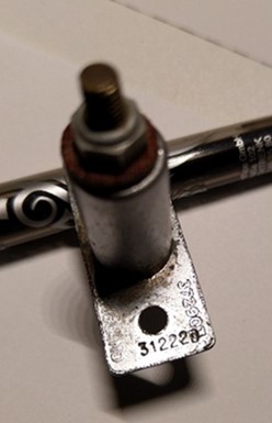
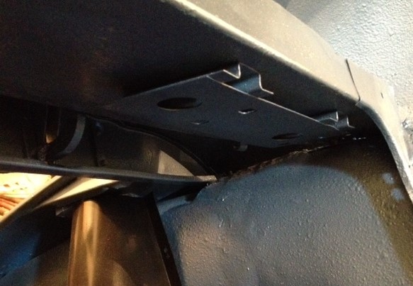
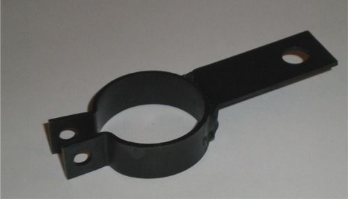
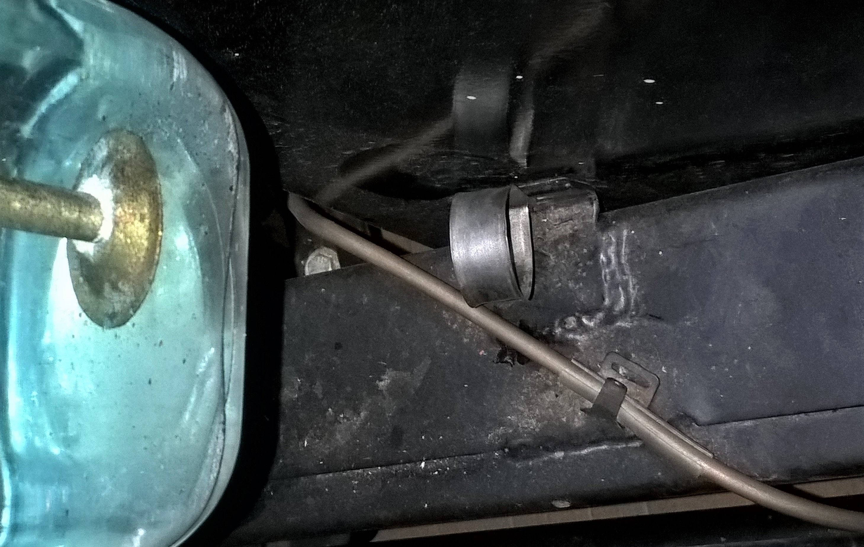
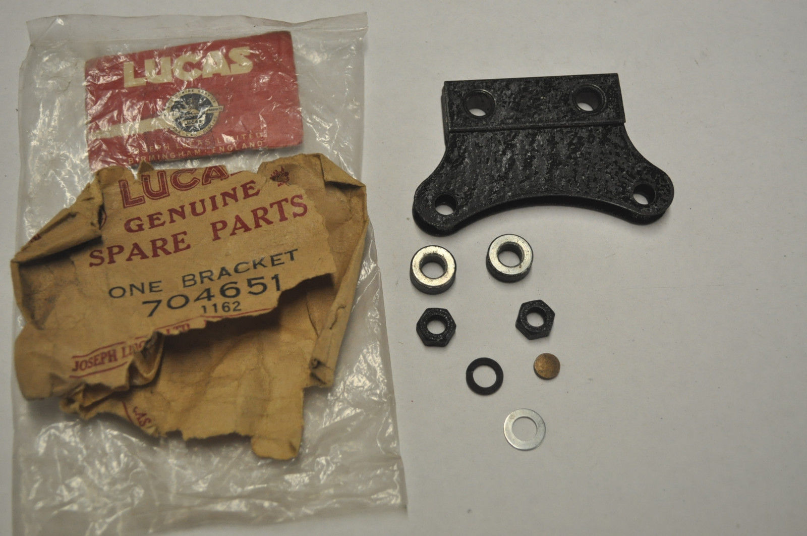
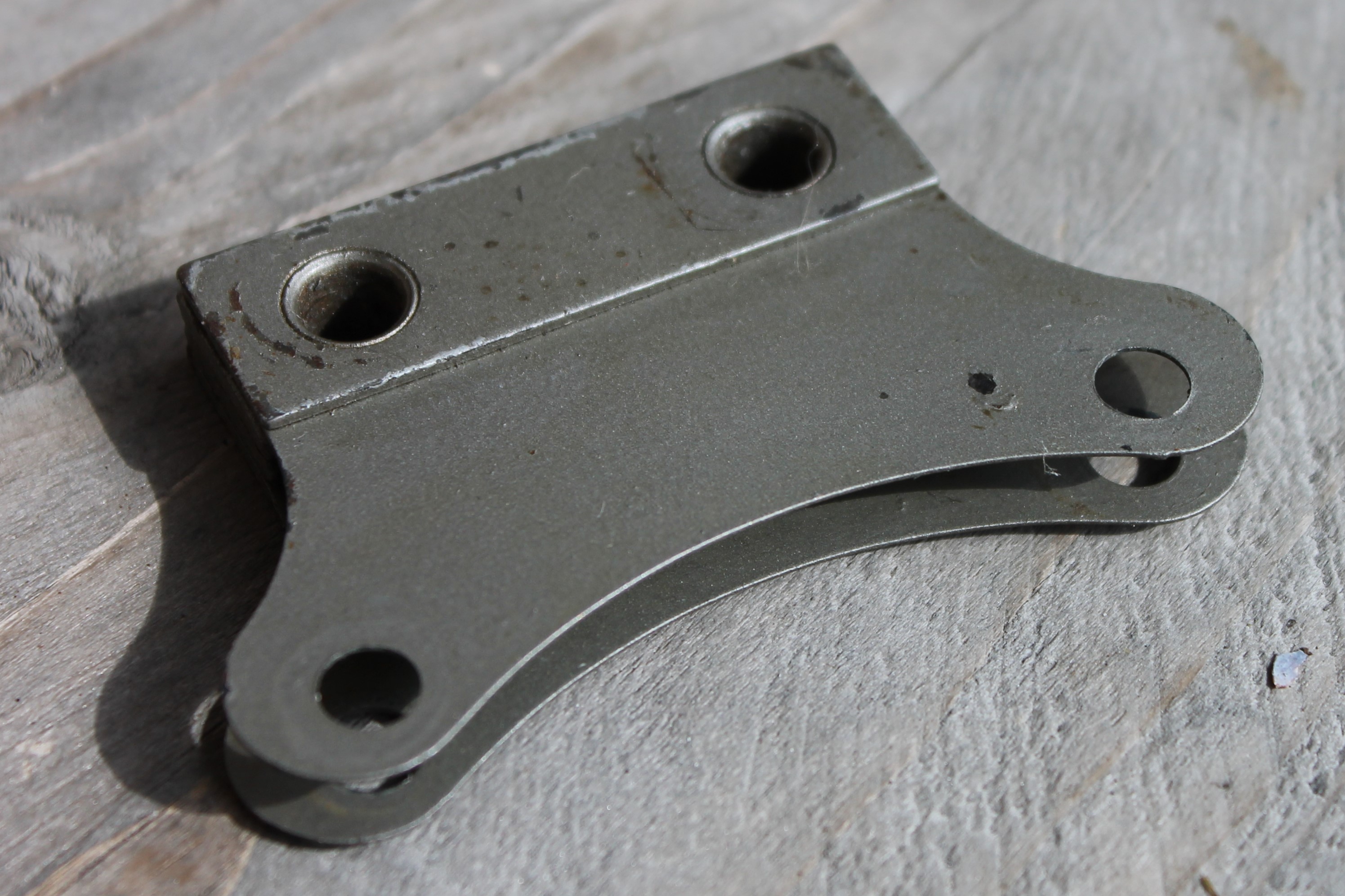
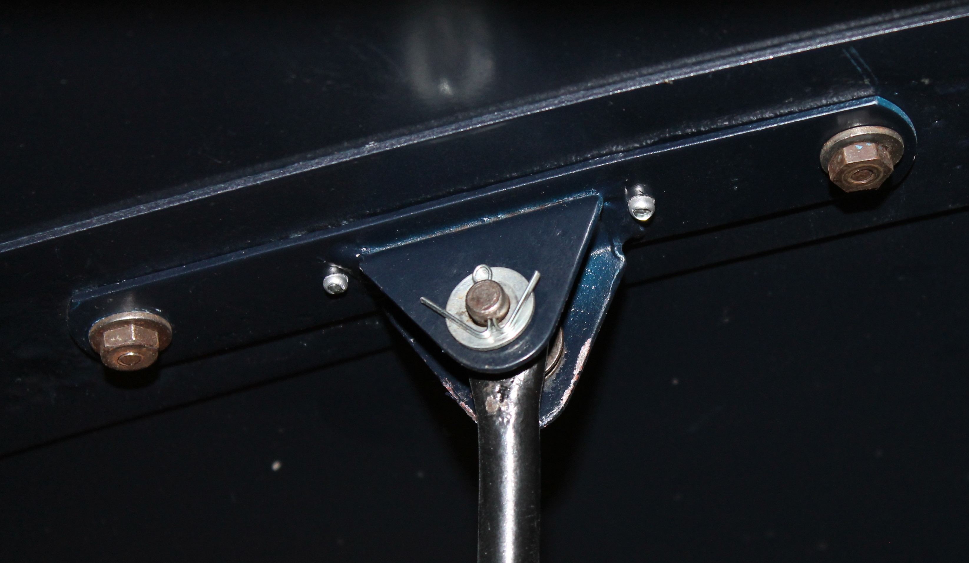
Note the early Radiomobile mounting bracket with single slit. (Photo’s Rob Reilly)
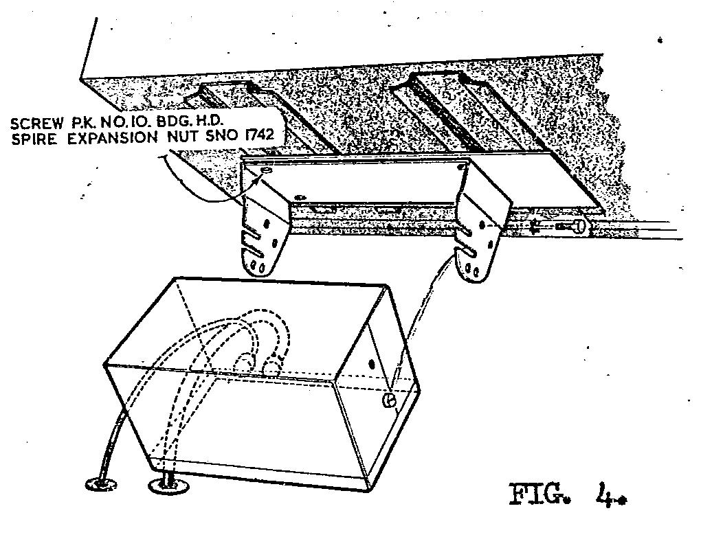
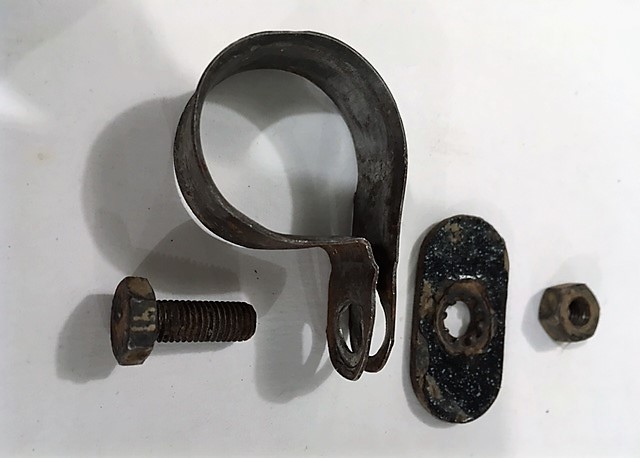
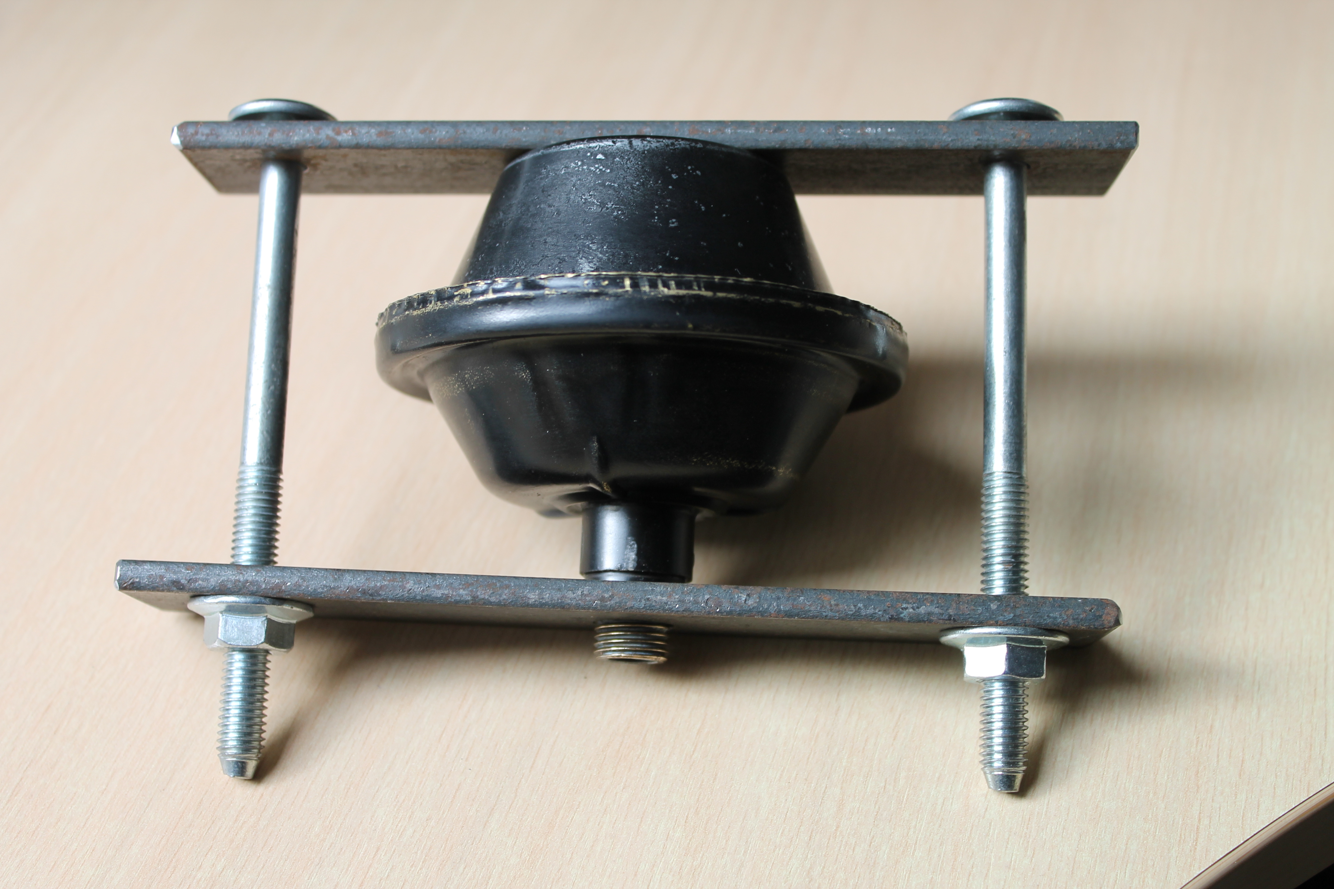
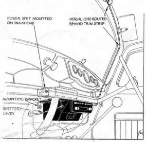
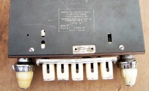
The Receiver (or Controller) was positioned in pace of the drawer for the DHC/FHC models and below the instrument panel on the OTS version using special mounting brackets (see picture below). As we will see there are three different brackets used for Amplifier mounting between 1951 and 1958:
- Bracket with single slot per side. Radiomobile code unknown.
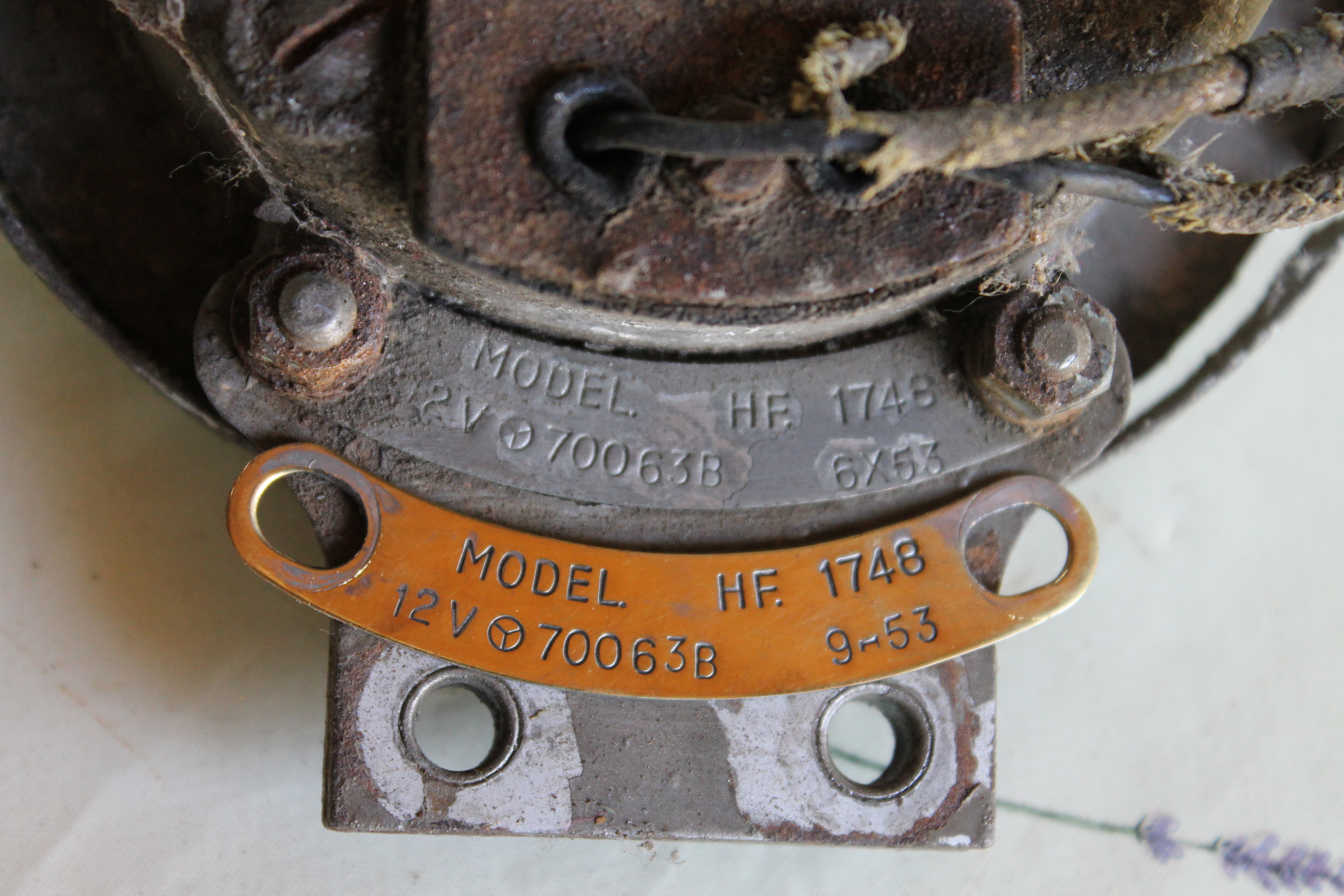
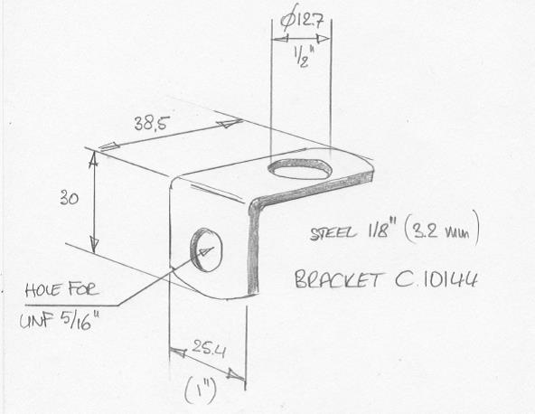
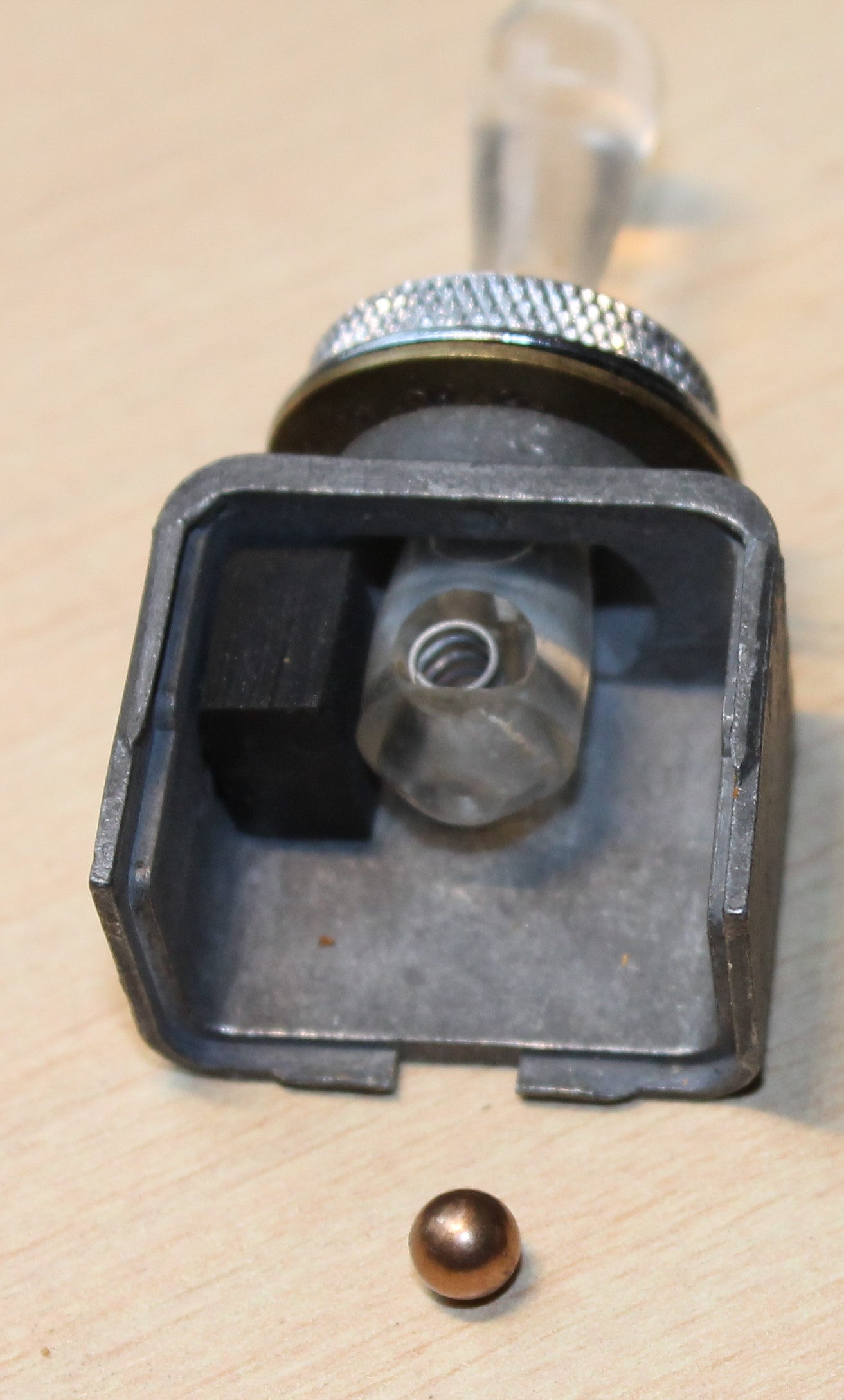
- Bracket with double slots per side. Radiomobile code RMO3451/BA and/or RMH93508. Jaguar C.11797
- Brackets with no slots for Transistor Amplifiers. Radiomobile code RMO3320/K
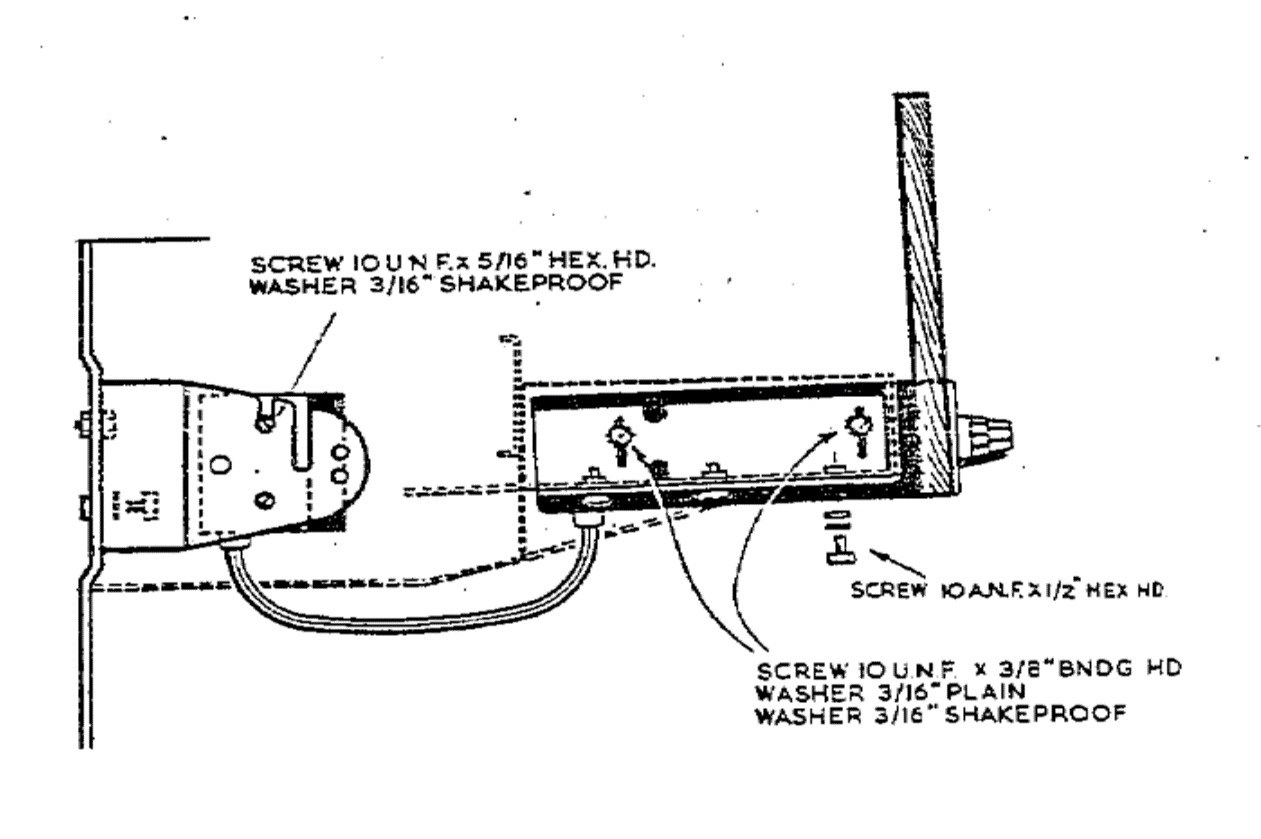
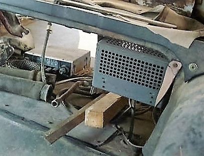
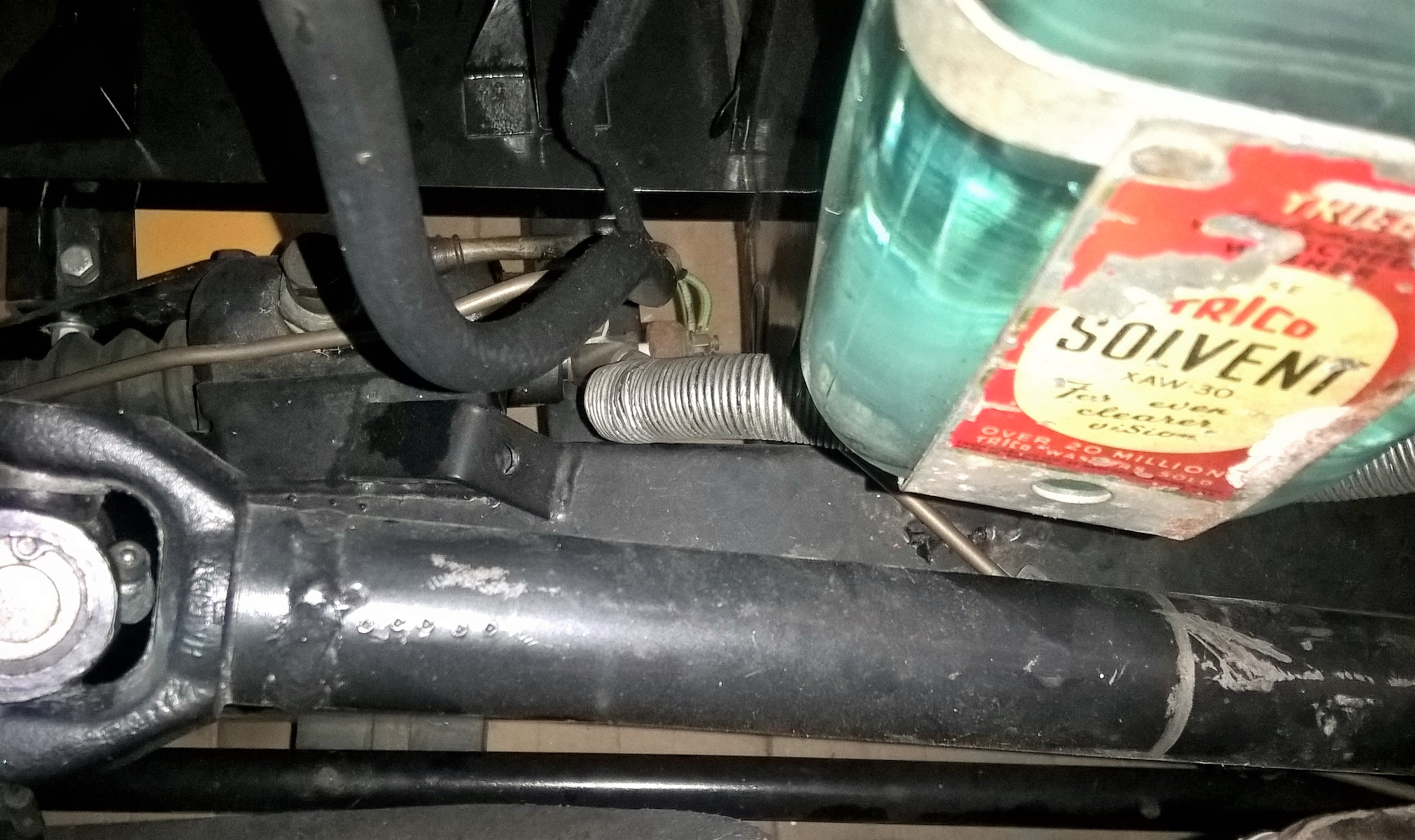
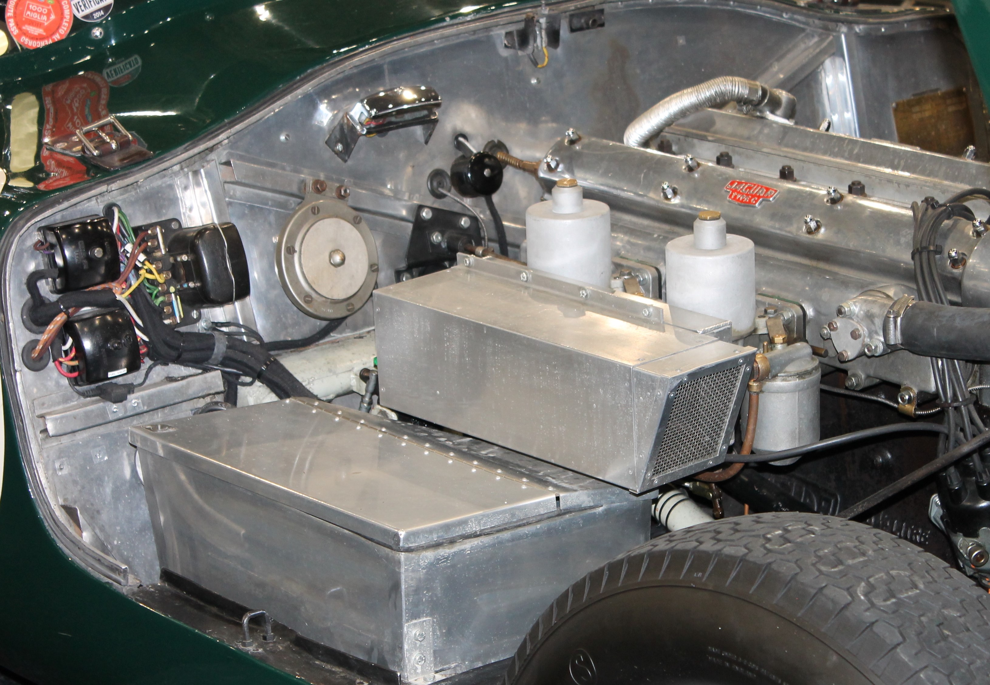
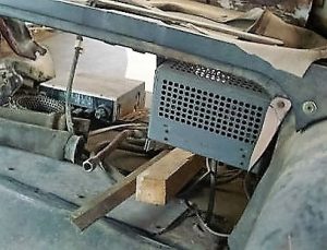
The DHC/FHC versions had the Amplifier (or Power unit) placed between the two 6 Volt batteries (positioned behind the seats) using the standard Radiomobile bracket supplied with the unit. The Amplifier unit has 3 sets of screw holes and can be attached at 3 different positions: wall mounted, shelf mounted or under the instrument panel.
 Early mounting bracket with single slits, positioned between batteries (Picture Roger Payne)
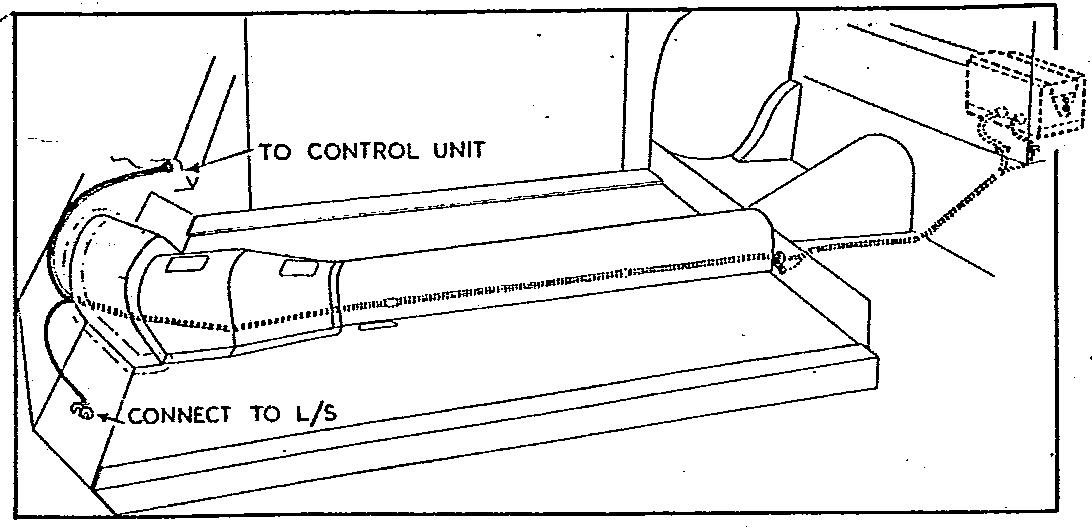
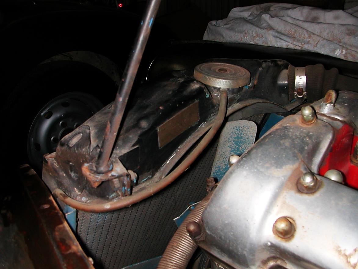
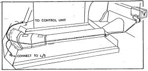
A long cable (with 8 pin connectors at both ends) runs from the amplifier to the receiver. The routing of the Amplifier cable is as follows: from the Amplifier Unit (mounted between the batteries) first horizontally to the front of the car at the left side of the transmission tunnel, secured by a “P” clip halfway the tunnel. The cable continues forward following the firewall upwards to the rear of the Receiver. The complete cable is hidden under carpets. See picture above right.
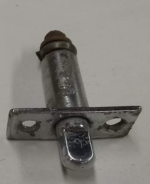
The OTS model often had the Amplifier mounted directly in front of the Radio Control up against the bulkhead, using the standard bracket provided with the unit. The Amplifier cable was much shorter then.
 Special brackets for XK 120 OTS model. Loudspeaker plug with 4 pins on earlier Amplifiers
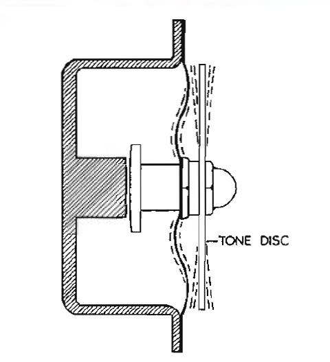
Cars built after 31 December 1951 had mounting holes pre-drilled and fitted with rubber blanking plugs if no radio installed by factory. The loudspeaker was located behind the seats. Another cable (with one 4-pin connector) connected the speaker with the Amplifier.
Although there are 4 pins on the plug, only 2 wires are used for connecting a loudspeaker. For the connection, we have to make a distinction between Amplifiers of Type A and Type B.
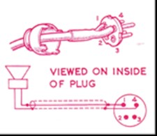
- For Type A amplifiers a speaker with impedance between 3 and 5 Ohms is connected to pins 1 and 2.
- For Type B amplifiers a speaker (or a combination of 2 speakers in parallel) with impedance of 2 to 3 Ohms should be connected to pins 1 and 3. For a (combined) speaker impedance of 4 to 5 Ohms pins 1 and 2 are used.
2.12 Price levels of 4100 and 4200 radio series
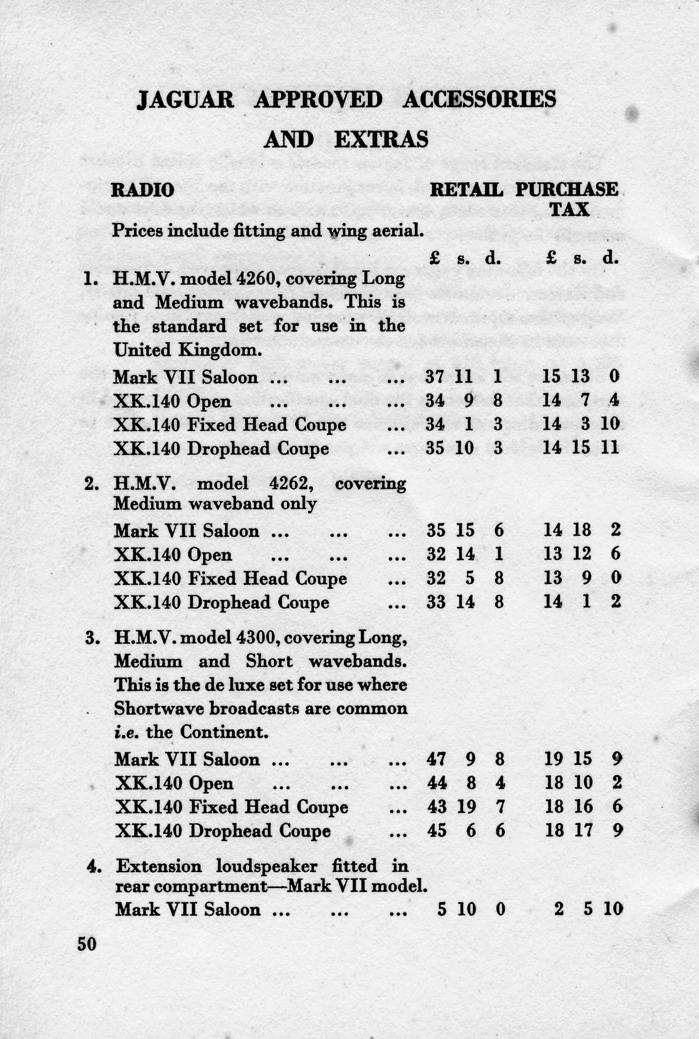
The Radiomobile brochure of August 1953 provides insight on the UK price levels of “aftermarket” radio sets per car model excluding installation cost. For the XK 120 Jaguar recommended Model 4200B with a total “kit” price of almost £41 (inclusive of purchase tax). As a reference: a complete XK 120 could be obtained for an amount around £1600 meaning the radio was at least 2.5% of the total cost. The simpler Model 4100 version had a kit price about £10 (about 25%) less than the 4200 series, which may also be the reason this model was rather popular with Jaguar customers.
The 1953 US price list shows two different radios: one for $115 (probably the Emitron 4102 with A type amplifier) and the other for $164 (probably Emitron 4202 model with B type amplifier). A complete XK 120 was between $4000 and $4600 depending on model and executions. The cost for the optional radio was thus between 2.5 and 3.5 % in the USA.
3. Radio installations offered for the XK140
3.1 Available “optional extras”
Whereas the “Salesman’s Data Book” for the XK 120 didn’t mention any radio as Optional Extras, the version for the XK 140 listed three different radio options:
1. Model 4260 with Long and Medium wave
2. Model 4262 with Medium wave only
3. Model 4300 with Long, Medium and Short wave reception.
 Page from Salesman’s data book: HMV 4260/4262/4300 (own photo)
The XK 140 Salesman’s data book had been edited late 1954 on the occasion of the XK 140 introduction as announced on 13th October 1954. Some of these radio models had been replaced late 1954 or early 1955 by versions listed below and we know that many XK 140’s had these later models, but a few 1954 and early 1955 XK 140 models may have these older types. It may also have happened that later XK 120’s had one of the above-mentioned radios installed. Apparently, the 4200 series never received Jaguar part numbers: none of the relevant SPC’s lists these radios. This is rather remarkable, as Jaguar even published UK retail prices for 1954.
In fact, none of the XK140 SPC’s listed any radio available as Optional Extras. There is sufficient hard evidence, however, that the 200 series have been applied on the XK 140 and Jaguar part numbers have been listed in other SPC’s.
- Model 200X with Long and Medium wave
- Model 202X with Medium wave only
- Model 230R with Medium and Short wave reception
Like the 4200 series of the later XK 120, the new HMV Radiomobile radios used on the XK 140 had a receiver, an amplifier unit and a loudspeaker as well as a (long) cable between receiver and amplifier and smaller leads to the loudspeaker.
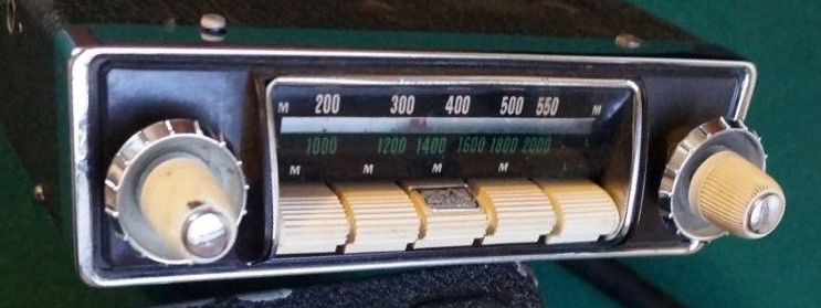
3.2 Model 4260 with Long and Medium wave (1954 – 1955)
The Model 4260 was a LW & MW receiver basically identical to its prececessor model Model 4200 but the design had been upgraded: the flat front and dial of the 4200 series had been replaced by a chromed rim around the scale and push-buttons. Jaguar still used the black knob and button versions for the XK 140 models, although there are indications that the Mk VII (M) versions may have had cream knobs and buttons.

 Two examples of HMV Model 4260 with cream or black knobs and push-buttons
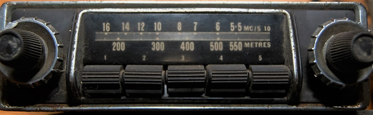
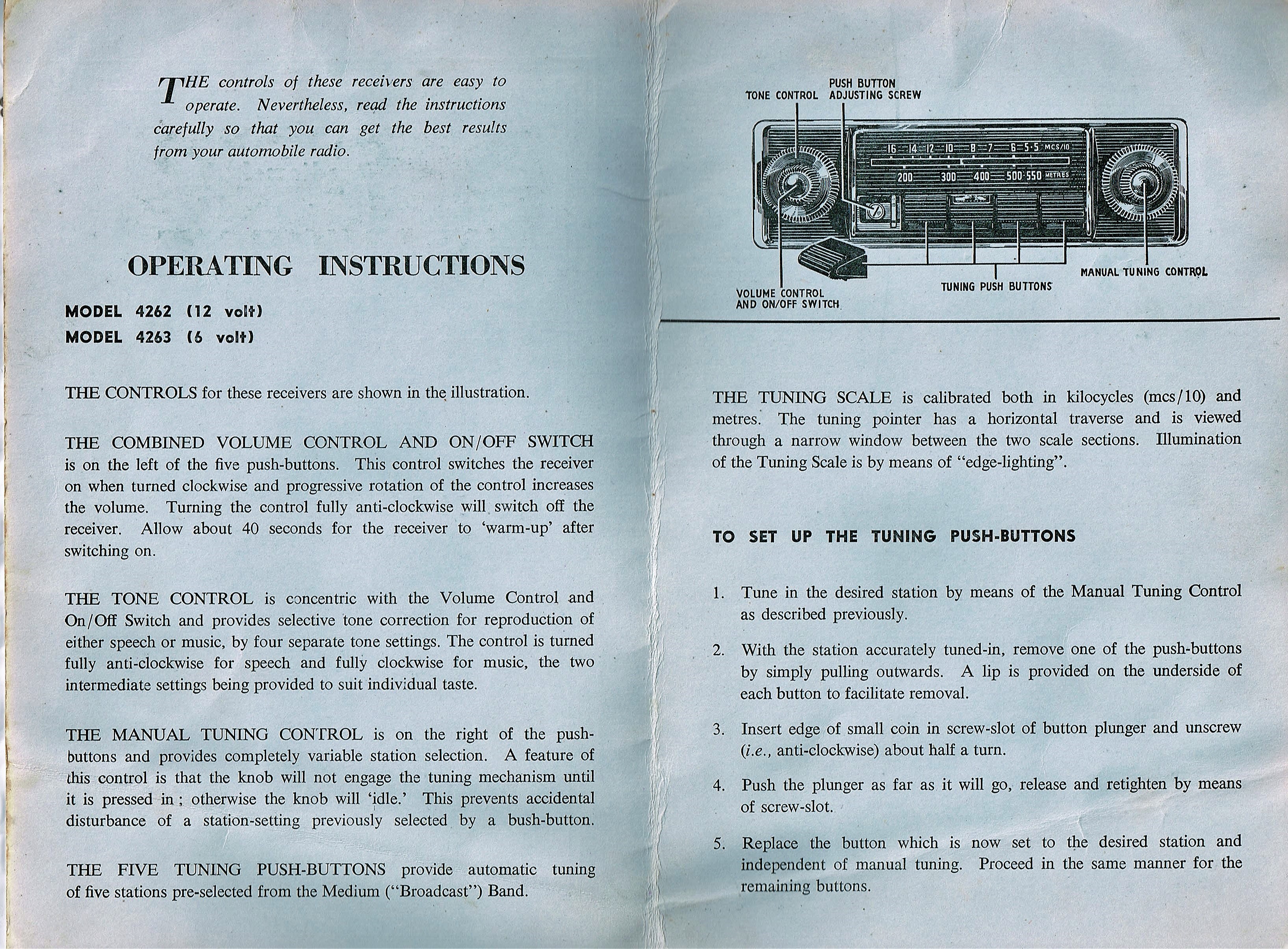
3.3 Model 4262 model with MW only (1954 – 1955)
This is a medium wave only radio, with 5 pre-set buttons. All knobs and buttons in black as (most likely) applied for the XK 140 models. The Medium Wave dial showed Metres and MC/S/10 (or better MHz/10) to get the same impression as the two lines of the Model 4260 receiver with one scale for MW and another for LW. Most “MW only” Radiomobile receivers use the same method for their dials.
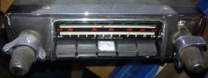
 Model 4262 with black knobs and push-buttons
As stated above, the Model 4262 of the Mark VIIM probabaly had cream push buttons and knobs, as can be seen in the photo below.
 Model 4262 in a Jaguar Mk VII Complete system Model 4262
Note that Model 4262 had a specific way of choosing the “pre-sets”, using a screw located behind the front of a push button that had to be removed. See Instructions below.
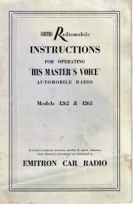
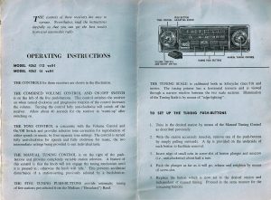 Instructions for Model 4262 dated February 1954 (Courtesy Roger Payne)
3.4 Model 4300 with Long, Medium and Short Wave reception (1954 – 1955)
The Model 4300 was the “high end” model of the 4260 series with Long, Medium and Short Wave reception and it superseded the Model 4050. Although technically related to the Model 4260 and 4262, this version was continued after the 1955 introduction of the Model 200X and 202X (replacing the Model 4260 and 4262).
 Model 4300 in black
3.5 Amplifier units
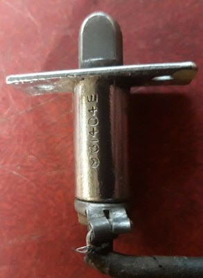
Two types have been used for the 4260 and 4300 series in the XK 140: Medium Output Type A with a 2.5 Watt output and the High Output Type B model with 6 Watt maximum output. This is a continuation of the Amplifier Units as used for the 4200 series with the 8 pin connector system. Further information: see paragraph 2.9.
3.6 Installation of the 4260 and 4300 series in the XK 140
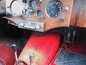
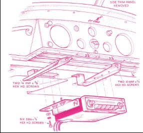
All radio’s mentioned above were of the “3 unit construction” consisting of a receiver (or controller), an amplifier (or power unit), connected via a thick cable with special 8-pin plugs at both ends, and a loudspeaker. The radio receiver part of the XK 140 was always mounted under the dashboard: for the DHC and FHC instead of the drawer, probably using special brackets replacing the original drawer brackets and slides.
The OTS version had the large separate amplifier (or power unit) mounted high under the dashboard on passenger side as was the speaker (facing down).
 Later brackets have two slits for horizontal mounting of the Amplifier (Picture provided by Roger Payne)
For the DHC and FHC the amplifier unit was mounted on a steel bracket RMO 3451/BA fixed under the parcel shelf at the LH side of the car.
In case of the DHC the speaker is mounted under the glove box, just as it was for the OTS versions. For the FHC the speaker was mounted in vertical elongated holes forward of the wing vent openings in the side panels. These black bitumen card trim panels actually had a perforated section that could be removed for the loudspeaker. Once the piece was pushed out, perforated aluminium was riveted over the hole on the rear of the panel. The possibility to have speakers on either side probably relates to the different driver positions in case of RHD or LHD cars, although the 7 Watt “High Output” amplifiers could also have two speakers installed.
In case the amplifier unit of the original Smiths Radiomobile is mounted under the parcel shelf in the boot, the (heavy) connecting cable runs under the floor to the radio receiver.
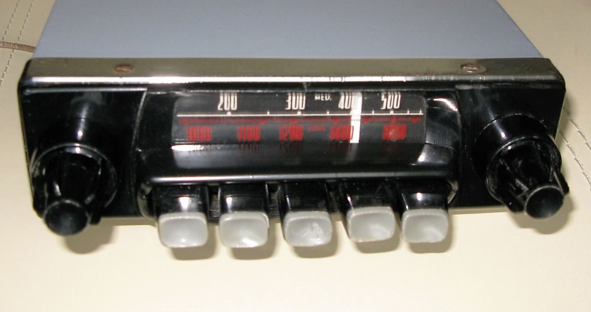
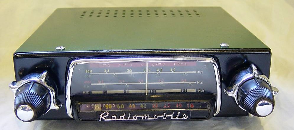
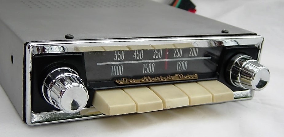
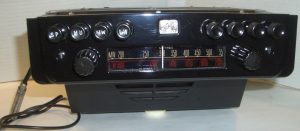
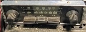
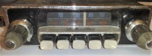
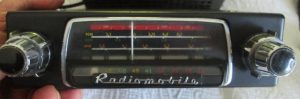
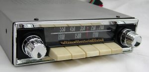
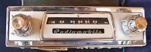
3.7 Model 200X with Long and Medium wave (1955-1957)
The new 200 series, introduced in January 1955, were the successor of the 4260 series and had a more “modern” design with a new HMV logo, but still with 5 push-buttons.
 Introduction of the new Model 200X
The 200 series consisted of two different basic versions indicated by the letter corresponding with the Amplifier used: XB or RB. The Model 200X (as shown below) was combined with the XB power unit.
 Model 200X in an XK 140
The receiver units have the same “looks” and only the type plate will tell whether it’s a X or R version. For the 200 series receivers, the 4 buttons acted as MW pre-sets and the 5th for choosing LW stations (no pre-sets).
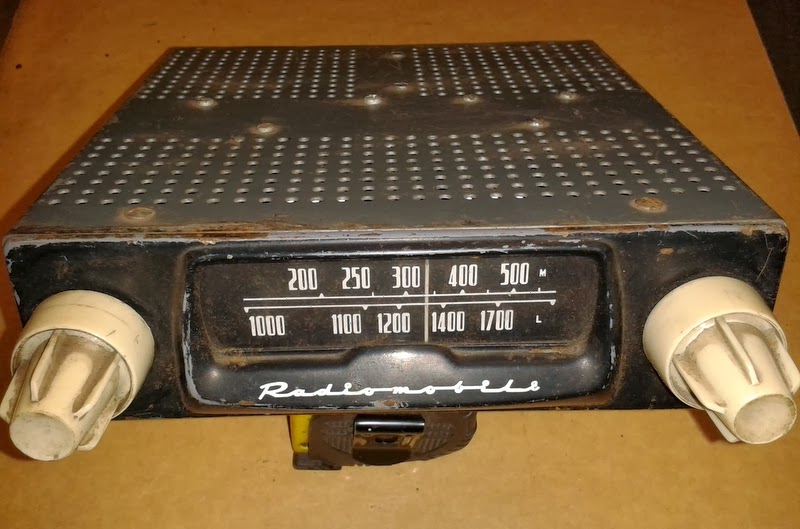
Jaguar used a specific receiver version with Radiomobile code RMH200X/VP and Jaguar part number C.11791. Radiomobile offered various choices for push buttons and turning knobs: full black and full white( cream), but also black push buttons with white fronts were an option. And Radiomobile also provided a choice of scales in white/white figures or white/red figures.Some radios had a chrome rim around the front.
Jaguar listed the RMH200X/VP version whereby the letters VP indicate the factory code for dial and knobs/buttons execution. There is ample proof that Jaguar factory-installed radios for the XK’s had fully black knobs and black push buttons with white fronts, but also a few complete black push-buttons have been observed.
 Model 200X radio with white MW and LW scale Model 200X with white scale for MW and red for LW
 Non-Jaguar 200X radio version with correct push buttons and “His Master’s Voice” on button cover but different knobs and chrome rim.
Note the (plastic) cover over the push buttons; this part is “snapped” to the dial plate with only two little plastic hooks and is therefore often missing after 60 years! Some (European?) versions have “His Master’s Voice” printed on the top of this cover.
In parallel to the Model 200X there was also a Model 200R to be combined with the more powerful RB amplifier unit. See photos below.

 Front of Model 200R is identical to 200X, To be combined with more powerful RB amplifier unit
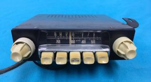
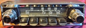
3.8 Model 202X with Medium wave only (1955-1957)
The Model 202X was a popular, simpler version of the 200X with Medium Wave reception only, which was especially sold in the USA. The photos below show versions with cream fronts on the (black) push-buttons which was (as stated before) the case for the majority of factory-installed Jaguar XK 140 radios. All 5 buttons now acted as pre-sets for MW stations.
In line with the above, there also was a Model 202R version to be combined with the more powerfull RB amplifier unit. The Jaguar part number for this receiver was C.11792.
 Note that versions for the USA were still Emitron branded/printed for the earlier described reasons. See photos above: note label showing model 202X made by Radiomobile.


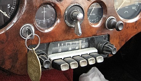
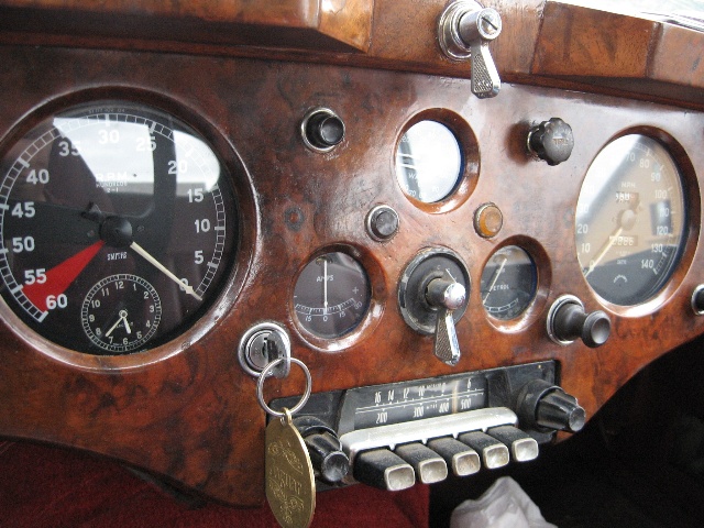
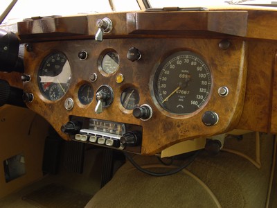
 Five examples of XK 140’s with Model 202X
 Model 202X in Mk VII
 Special version for Australia with specific stations per state on the scale. Black fronts of push buttons but missing cover (Photo: Roger Payne)
The photo above shows an original HMV (Radiomobile) radio fitted in a late 1954 DHC sold new in Australia. Note the HMV logo on the centre push button. Radiomobile provided special scales per state (or combinations thereof) in Australia to indicate local stations.
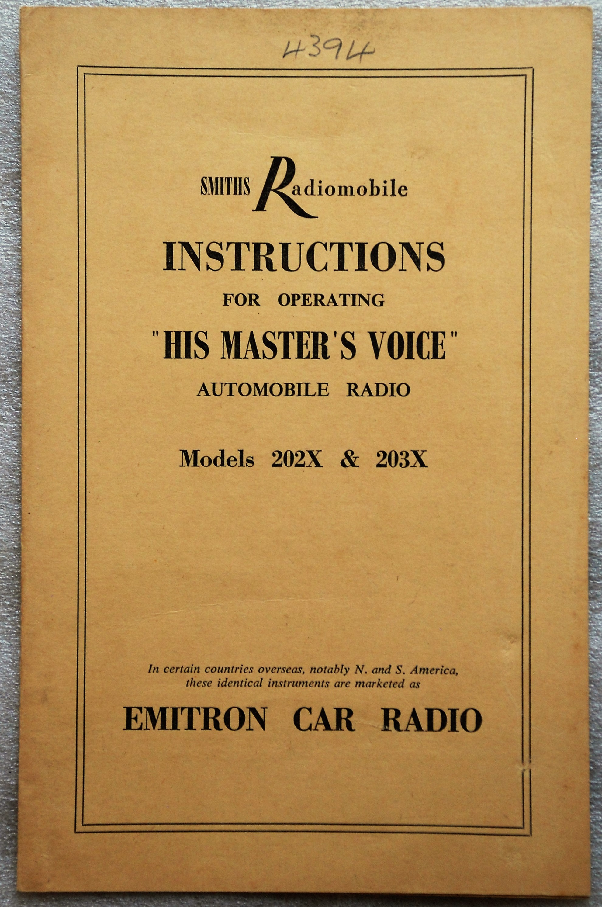
 Operating Instructions 200 series radios incl. Emitron in USA.
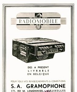
 Also sold on the Continent: 1955 Belgian ad
3.9 Other 200 series radios
The 200 series was an extensive range with many different models. Again, although not “Optional Extras”, some of these versions may have ended up in a Jaguar XK via dealers especially in the former “Commonwealth” countries. A short survey:
- Model 201X 6 or 12 Volts switchable version of Model 200X.
- Model 203X 6 or 12 Volts switchable version of Model 202X.
- Model 212X 6 or 12 Volts switchable version of Model 200X with adjustable polarity.
- Model 213X 6 or 12 Volts switchable version of Model 202X with adjustable polarity.
- Model 220X 12 Volts only, identical to Model 200X but economy model without push-buttons
- Model 221X 6 or 12 Volts, identical to Model 200X but economy model without push-buttons
Note that each of the above models required a particular Amplifier corresponding with the features of the radio: voltage, polarity and output power. E.g. the Model 220X (a type mentioned by Radiomobile as being correct for the XK 140; see also 3.13) was supplied with amplifier XE and Model 221X with amplifier XF. See paragraph 3.10.
3.10 Amplifier Units for the 200 series
A new amplifier type had been introduced for the 200 series. In order to avoid that later amplifiers could be connected to earlier radios (and vice versa) the new generation had a 5-pin plug instead of the old 8-pin plug system. In addition the loudspeaker cable now had a 3-pin plug instead of the 4-pin system of the previous generation. The “X” range had two versions with a different power output. The new “R” range had an adjustable polarity switch and consisted of 4 types (only 12 Volts versions listed here).
The Radiomobile code for all amplifier units was Model 92450, but followed by the amplifier type e.g. /XB or /RB. Note that Jaguar recommended the more powerfull “B” units only: either 92450/XB or 92450/RB.
For the 200 series Jaguar used only the 92450/XB version with part number C.11796.
- XA 12 V; two valve standard amplifier for 1 speaker; positive to earth; maximum output 2W
- XB 12 V; three valve “De Luxe” amplifier for 2 speakers ; positive to earth; maximum output 5W
- XC 6 or 12 V switch; maximum output 2W
- XD 6 or 12 V switch; maximum output 5W
- XE 12 V; adjustable polarity; maximum output 2W
- XF 6 or 12 V switch; adjustable polarity; maximum output 5W
- RA 12 V; adjustable polarity; 2 valve; maximum output 2W
- RB 12 V; adjustable polarity; 3 valve; maximum output 5W
- RC 6 or 12 V switch; adjustable polarity; 2 valve; maximum output 2W
- RD 6 or 12 V switch; adjustable polarity; 3 valve; maximum output 5W
 New (round) 5-pin connector type plugs on XB and RB power units. Speaker plug has 3 pins.
 Detail of 5-pin connector plug.
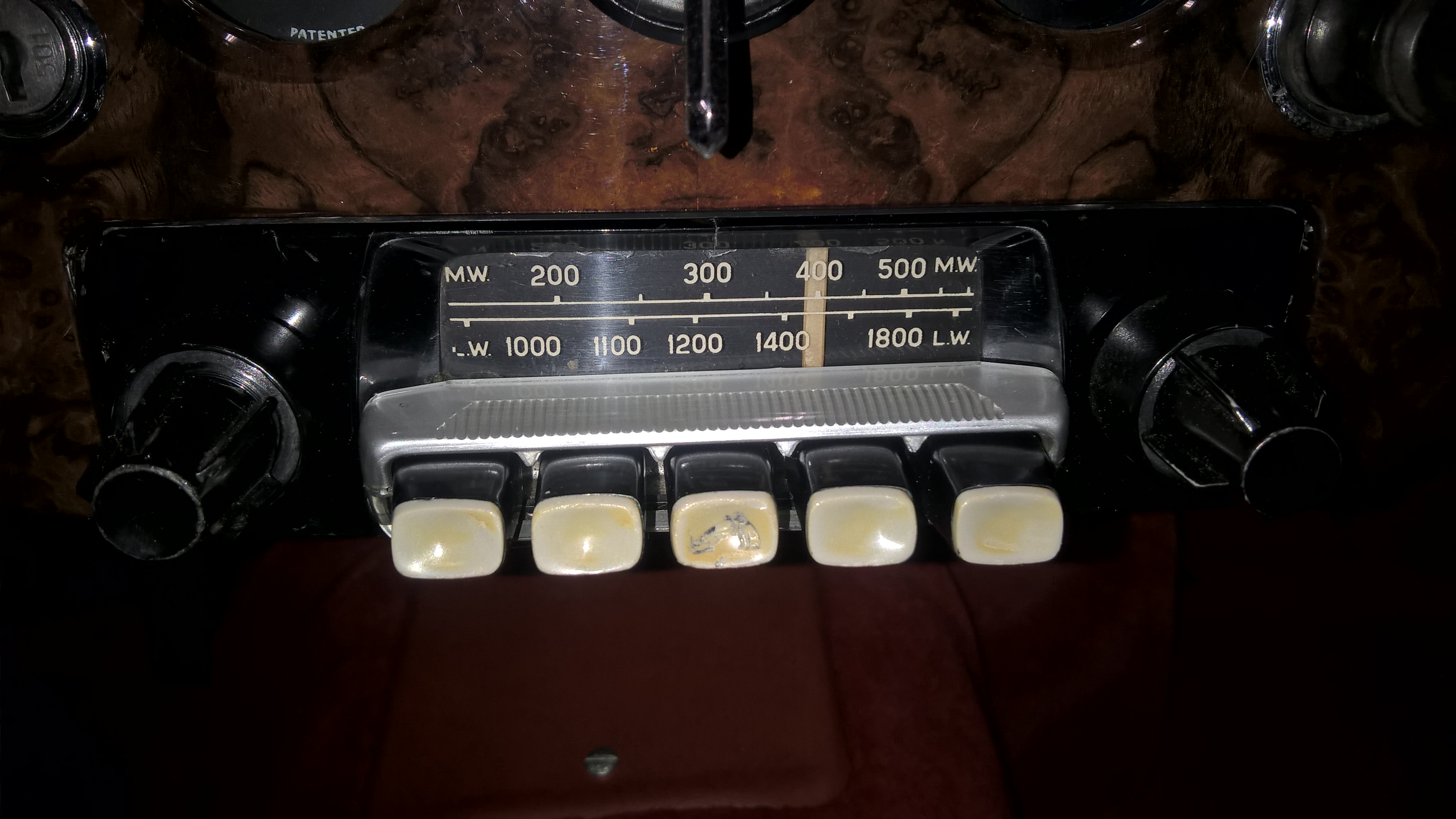
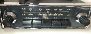
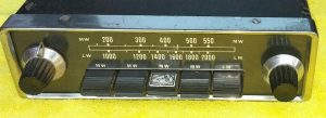
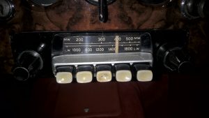
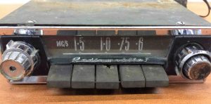
3.11 Model 230R with Medium and Short wave (1955 – 1960)
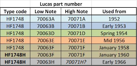
The Model 230R was a version that “survived” a number of Radiomobile radio generations as it was used for more than 5 years, offered both in the Jaguar XK 140 and XK 150. The model was still of the “3-unit construction” with a separate Amplifier of the RB type. It had a receiver for MW plus 8 SW bands: 90m, 60m, 49m, 41m, 31m, 25m, 19m, and 16m therefore suitable for a number of non-European and non-NA countries. Jaguar describes this version as the RMH 230R/VB, the suffixes indicating the execution of dial and knobs. Note that the 200X and 202X version had suffixes /VP or even /VP.26. Other Jaguar models apparently had different knobs and/or dials: as an example, the Mk2 version had RMH 230R/BCU. The exact meaning of these suffix codes are not known (yet).
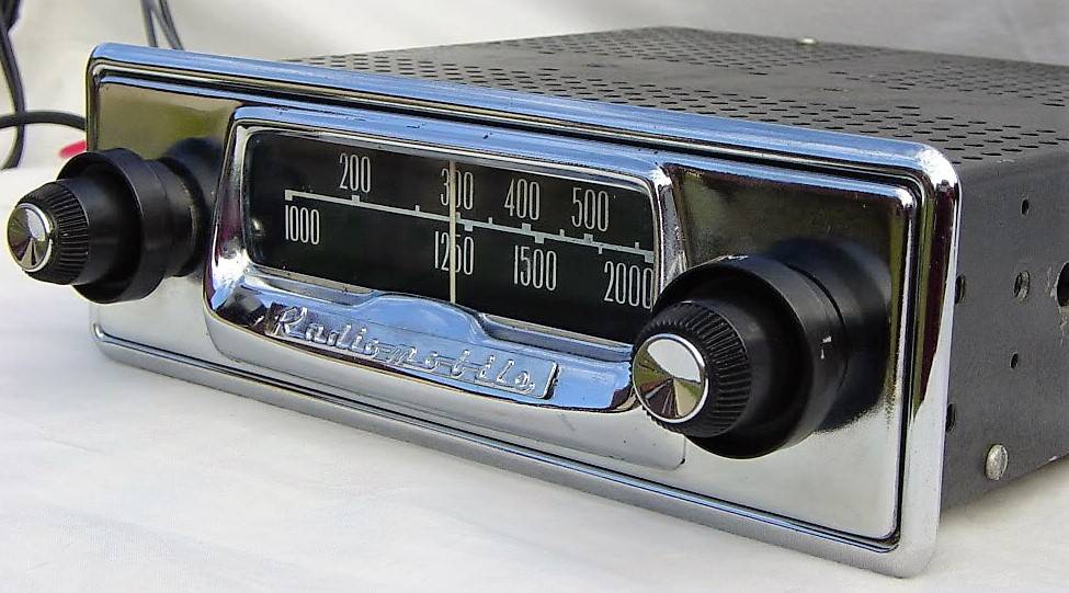
 Model 230R was Radiomobile branded, not HMV
3.12 Amplifier Units for the 230 series
The RM 230R was supplied required the more powerful RB amplifier with code 92450/RB. This range of amplifiers consisted of an RA type with single output and the aforementioned RB version suitable for two speakers. See information in 3.10. Jaguar only used the 92450/RB version with part number C.11687.
3.13 Installation of the 200 and 230 series in XK 140’s
The original “Smith Radiomobile installation instruction for 200X, 202X, and 220X for the Jaguar XK 140” describes the radio installation which is in principal the same for OTS, DHC and FHC.
In case of XK 140 DHC and FHC models, the receiver is installed in place of the “drawer” in the instrument panel using special brackets replacing those to which the drawer slides have been mounted. For the OTS model the receiver is mounted with special brackets beneath the dashboard.
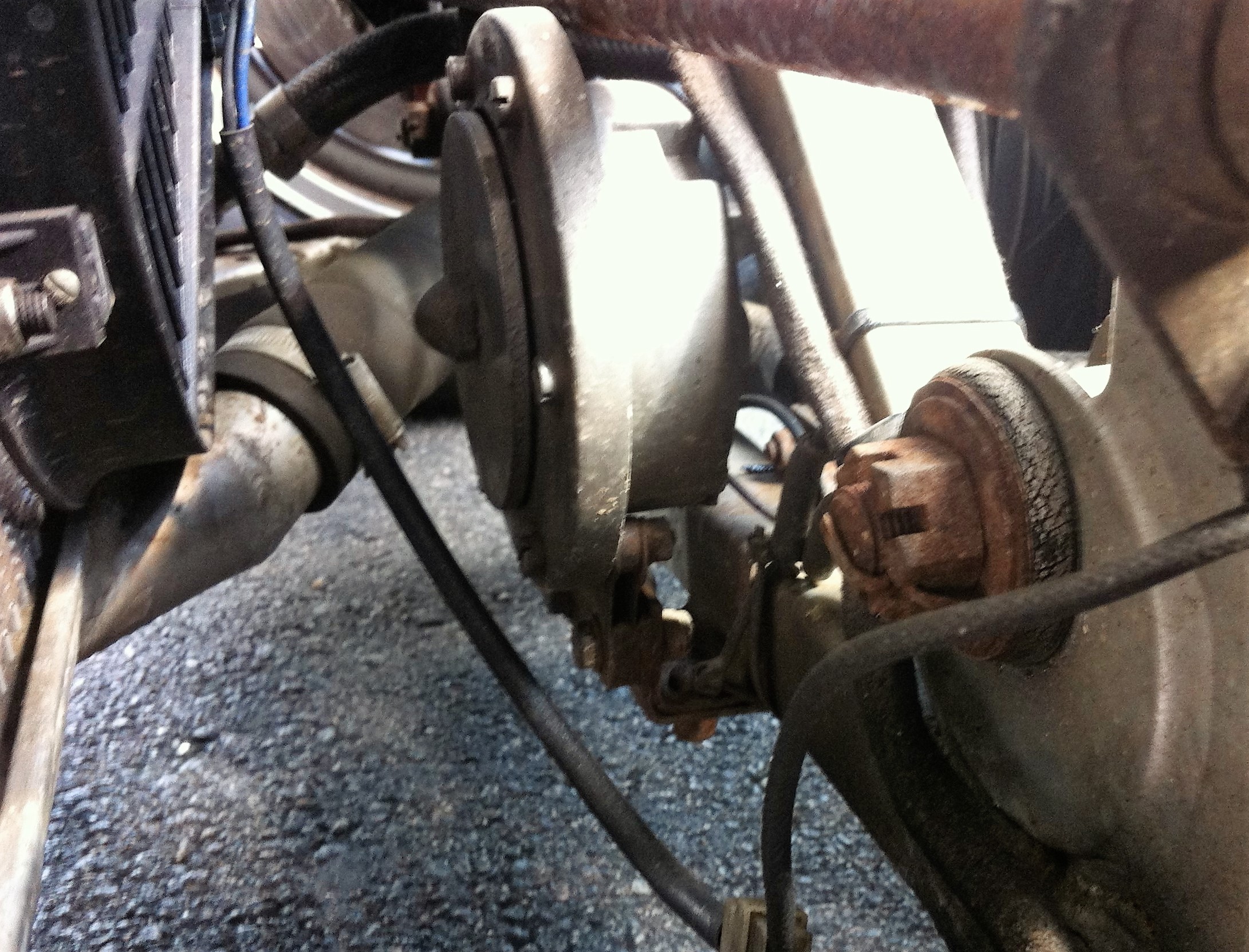
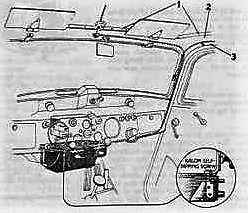
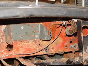
Jaguar had mounted a special steel bracket under the parcel shelf for the Amplifier (or Power Unit) during production, whereby the OTS and the FHC models shared the same bracket with Jaguar part number BD.9541: “Plate and Bracket assembly for mounting of Radio Power Pack“. The DHC had a different Jaguar part number for the bracket: BD.8926 “Plate inside Luggage Compartment for mounting of Radio Power Pack when required”.

 Jaguar part number BD.9541 : “Plate and Bracket assembly for mounting of Radio Power Pack” in a XK 140 FHC.
The bracket provided by Radiomobile for the amplifier unit was fixed under the Parcel Shelf on the left side in front of the Petrol Filler. All XK 140’s had such a factory built mounting plate, no matter whether a radio had been ordered or not. The XK150 had a similar mounting plate at the left side of the boot (instead of the top).
Radiomobile used two different codes for the Amplifier Bracket: RMH 93508 and RMO 3451. The latter has Jaguar part number C.11797.
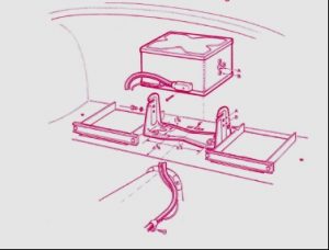
 Amplifier installation method for DHC & FHC models
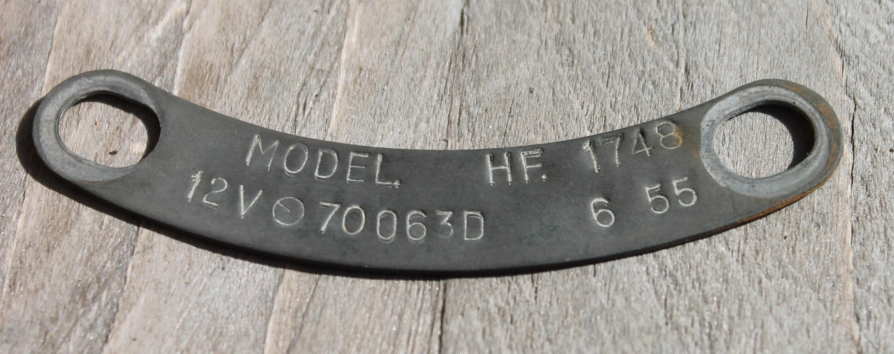
 Later Bracket RMH 93508 has two slots.
The loudspeaker is mounted in a pre-cut hole in the millboard that covers the footwell vent on the right side. This hole has an oval shape roughly 3” by 8” for the standard Radiomobile speaker. The left side had no pre-cut hole.
 Cable routing XK 140 (and 150)
The cable with the two 5-pin connectors runs from the receiver to the amplifier (length 120”or 305 cm) and a second cable with one 3-pin connector (length 168” or 427 cm) runs from the amplifier unit to the loudspeaker in the front.
3.14 Typical price levels of 4260 and 4300 series radio systems
The Jaguar 1955 UK price list for the XK 140 shows retail prices around £33 for Model 4262 in the FHC up to over £45 for Model 4300 in the DHC (these prices include fitting, aerial and tax). The total UK price (October 1955) for an XK 140 varied between £1600 and £1860, the latter for the XK 140 FHC in Special Equipment (MC) form, which means the cost of a radio was between 2 and 2.5% of the car.
In the USA prices for the (standard) XK 140 versions had meanwhile been lowered and was now at a level of $3460 (OTS) to $3800 (DHC/FHC) with an additional $450 to pay for the MC version. No 1955 prices are known for the optional radios but we may assume that prices remained at the 1953 level of $115 to $164 or around 3.5% of the total car price.
4. Radio installations offered for the XK150
4.1 Available “optional extras”
It is well known that most Jaguar Spare Parts Catalogue (SPC’s) are not up to date as to the applied parts in production. The XK 150 Spare Parts Catalogue (J.29/1 1960/1966) is no exception and lists the following (1955 introduced) radios available as “Optional Extras”.
- Model 200 X with Long and Medium wave
- Model 202 X with Medium wave only
- Model 230 with Medium and Short wave reception
These radios have already been listed for the XK 140 in the previous chapter and described there in detail.
We first must take a closer look at the way Radiomobile structured their product portfolio. Before 1955 the programme was in composed of high end and low end versions within each new series of radios. From 1955/1956 onwards the portfolio was much more structured having two distinct levels:
- a “low end” Radiomobile branded “single unit” radio combining receiver and amplifier.
- a “high end” His Master’s Voice branded “3-unit” radio (receiver, amplifier and speaker).
Over the period 1955 till 1961 the Radiomobile “low end” single units have been coded 20, 40 and 50 series, whereas the “high end” His Master’s Voice radios were coded 200, 400 and 500 series. It looks like the US delivered “high end” radios gradually were all Radiomobile branded while in Europe the His Master’s Voice brand was continued. After 1961 the “high end/low end” policy continued for some years but the branding became Radiomobile only (starting with the 600-series launched in 1962). The “low end” series remained initially based on the design of the 200 series, without the push-buttons however. The design of the “high end” series moved towards a “De Luxe” version with the His Master’s Voice name prominently shown above the push-buttons.
The Radiomobile Installation Instructions for the XK 150 DHC & FHC of June 1957 mention Model 20X and Model 22X radios in addition to the 200 series. Other available Radiomobile versions have hardly been mentioned in Jaguar literature. However, all below mentioned radios may have been used in the XK 150 and therefore each version will be described hereafter.
For completeness, the Radiomobile Installation Instructions for the Mk VII, Mk VIII and Mk IX of January 1959 mention Model 40T, 41T, 42T, 400T, 401T and 402T as the available options. We may assume that the Mk VII has been mentioned in these instructions for retrofitting these radio types in existing cars, as production of the Mk VII had been stopped in 1956.
- 20 series
- Model 20X with Long and Medium wave
- Model 22X with Medium wave only
- 400 series
- Model 400T Long & Medium Wave
- Model 401T Long & Medium Wave; polarity switch
- Model 402T Medium Wave only; polarity switch
- 40 series
- Model 40T Long & Medium Wave
- Model 41T Long & Medium Wave; polarity switch
- Model 42T Medium Wave only; polarity switch
- Model 42TC Medium Wave; polarity switch; tone control
- 500 series
- Model 500T Long & Medium Wave
- Model 501T Long & Medium Wave; polarity switch
- Model 502T Medium Wave only; polarity switch
- Model 530T Medium & Short Wave; polarity switch
- 50 series
- Model 50T Long & Medium Wave
- Model 51T Long & Medium Wave; polarity switch
- Model 52T Medium Wave only; polarity switch
- Model 52TC Medium Wave only; polarity switch; tone control
4.2 Radiomobile 20 series (1956 – 1958)
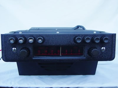
The “20 series”, introduced June 1956, marks the beginning of the era of miniaturization, having a compact “single unit” construction. Although it still contains (3) valves it lacks a separate amplifier unit of the previous generations. For the first time this Radiomobile model had a Selenium Rectifier replacing the vacuum tubes that had been used sofar.
 Model 20X in black (left) and with cream knobs (right)
Model 20X is a MW and LW receiver suitable for both “plus” and “minus” to ground. This was the period in which all car manufacturers gradually changed over from positive ground to negative ground and this new model was suitable for both.
As the photo above clearly shows, the 20 series is closely related to the 200 series: the same front lay-out and knobs have been used, however without the push-buttons, necessitating the introduction of a new injection moulded front. The Radiomobile brand name is prominently shown below the scale, which had been started with Model 230. The HMV name or logo is no longer used on these “low end” models. Again variations in colour and shape of knobs were available from the factory.
Model 22X is identical to the 20X version, apart from the fact that this is a MW only radio. Note that there was also a Model 30X which was however a “short-wave converter” to be used in combination with any radio to facilitate SW reception using 8 bands.
Radiomobile also offered Model 30X series, but this was merely a SW converter to be connected to a non-SW radio.
 Model 30X was a SW converter
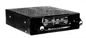
4.3 His Master’s Voice 400 series (1958 – 1960)
The new 400 series replaced the 200 series by the end of 1958 and still had the “3 unit construction”. Whereas the receiver unit had 5 valves, the amplifier was now fully “transistorised”, replacing the radio valves of the past. As stated before, the His Master’s Voice name is prominently shown on these “high end” versions. The new 400 series consisted of three models: Models 400T, 401T and 402T.
- Model 400T had LW and MW reception with 5 preset push-buttons and had positive earth.
- Model 401T was in fact identical to the 400T version, but had a polarity switch.
 Model 400T
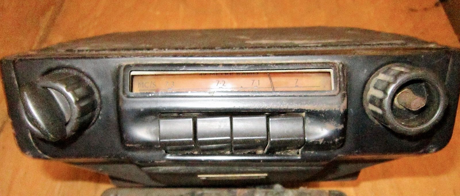
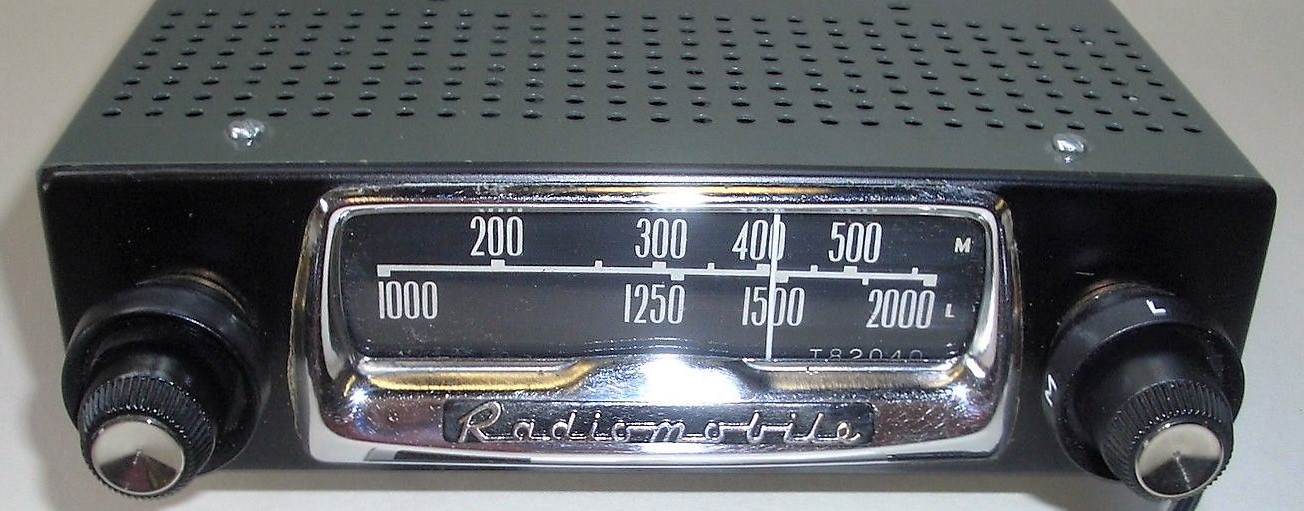
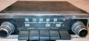
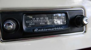
Model 402T also had the polarity switch of the 401T model but was Medium Wave only. Note that on the photo below of a Model 402T, the scale is only showing MC/S (or MHz) values for US customers. Metres are normally used in Europe as we can see on the Model 400T photo above. Note that the 402T shows the Radiomobile brand instead of His Master’s Voice. It looks like the US delivered radios now were all branded Radiomobile while the European (including UK) delivered versions were still His Master’s Voice. The question remains what had happended to the Emitron brand in the late Fifties?
 Radiomobile Model 402T. Here shown in a 1961 XK 150. No His Masters Voice for US customers! Photo: rmsothebys.com
Note that some XK 140’s have been observed fitted with the Model 402X; this must be a later installation.
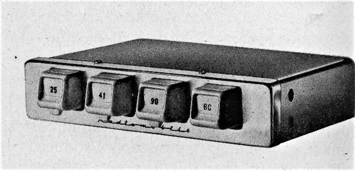
4.4 Radiomobile 40 series (1958 – 1960)
The 40 series (introduced late 1958 or early 1959) was the successor of the 20 series. Whereas the 20 series had a “X” suffix the 40 series had a “T” suffix for “Transistor”. The 40 series was almost identical to the 20 series but had 4 valves (instead of 3) and an amplifier with a single “power transistor” having a maximum output of 1.75 W, all packed within a single unit. The speakers should have an impedance of 3 Ohms or 1.75 Ohms, depending on the contacts chosen in the (3 pin) speaker connector.
 Model 40T with MW and LW
 Model 42T with MW only
Model 40T had LW and MW reception; no push-buttons. It was delivered suitable for positive earth. Model 41T was identical but had reversable polarity. Model 42T (photo above) also had the reversable polarity but this was a MW only radio. Finally there was the identical Model 42TC which had “Tone Control” in addition.
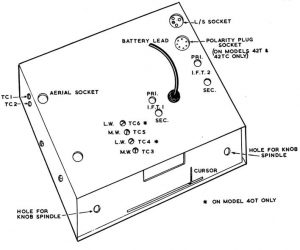
Underside of 40 series; note Polarity Plug Socket (RH top corner)
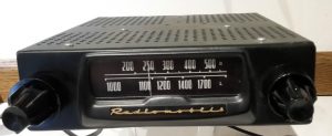
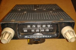
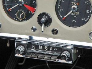
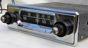
4.5 His Master’s Voice 500 series (mid 1959 – mid 1961)
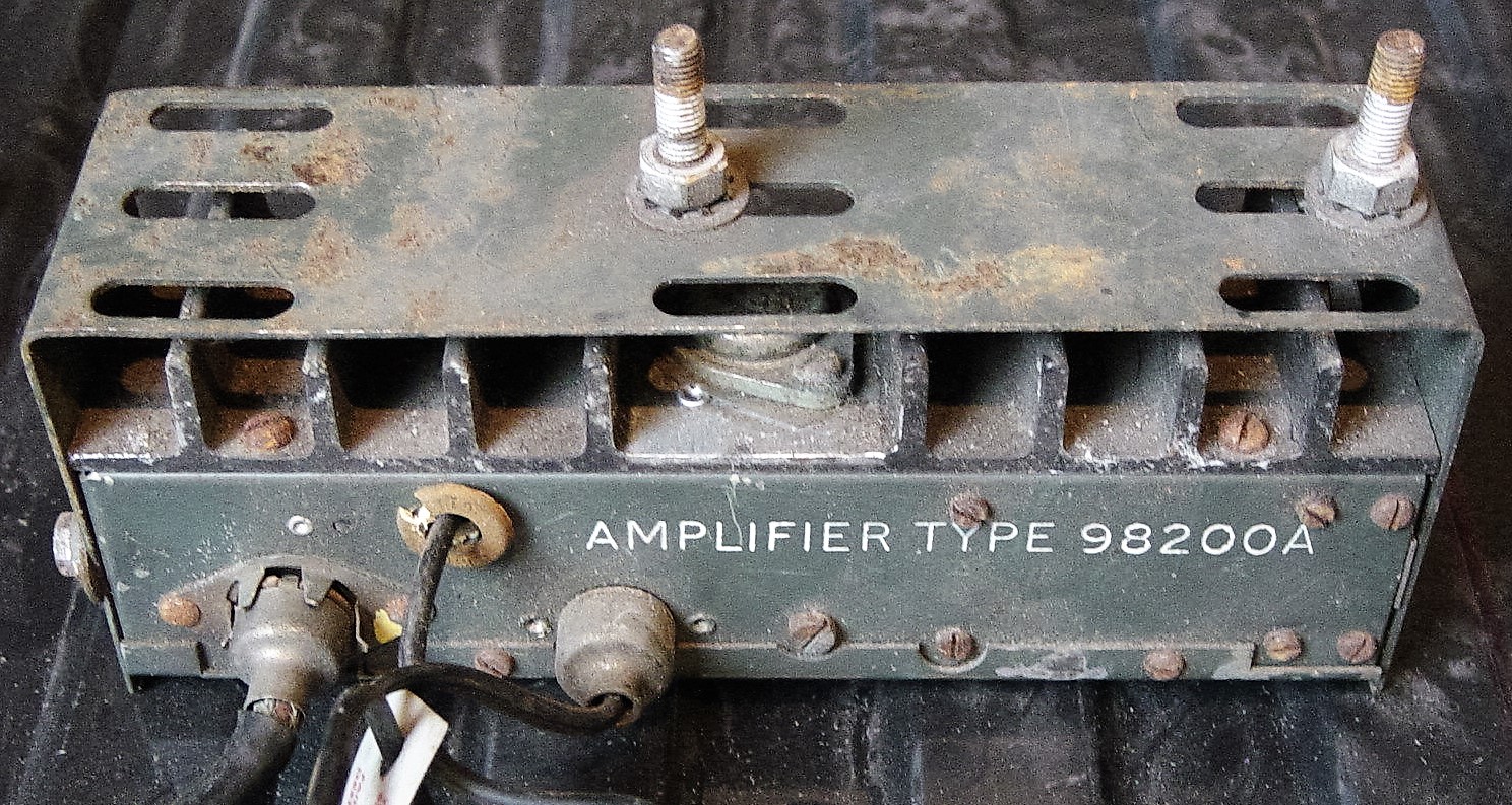
Introduced around 1960, the 500T series was the successor of the 400T series. The amplifier units remained identical for the two series. The 500 series also offered four models: Model 500T, 501T, 502T and 530T. The 500 series had “oval” instead of “square” push buttons. It was replaced by the 600T series in September 1961.
This model is listed in the Mk IX Spare Parts Catalogue, but we know it was also available for the XK150 in the 1960’s. Only the RMH.500TB and the RMH.502TB have been listed by Jaguar with Jaguar part numbers 8265 and 8264 resp. Note that the B behind the T suffix of the receiver refers to the amplifier type that is used in combination with this receiver: here the RMH.98200B with Jaguar part number 8267. See more info in 4.7. Note that the 500 series was also used in very early E-types, succeeded by the 600 series from mid 1961.
 Model 500T with black knobs and “oval shaped” push-buttons
 Model 501T is identical to 500T but has polarity switch (not yet required for Jaguars of this period)
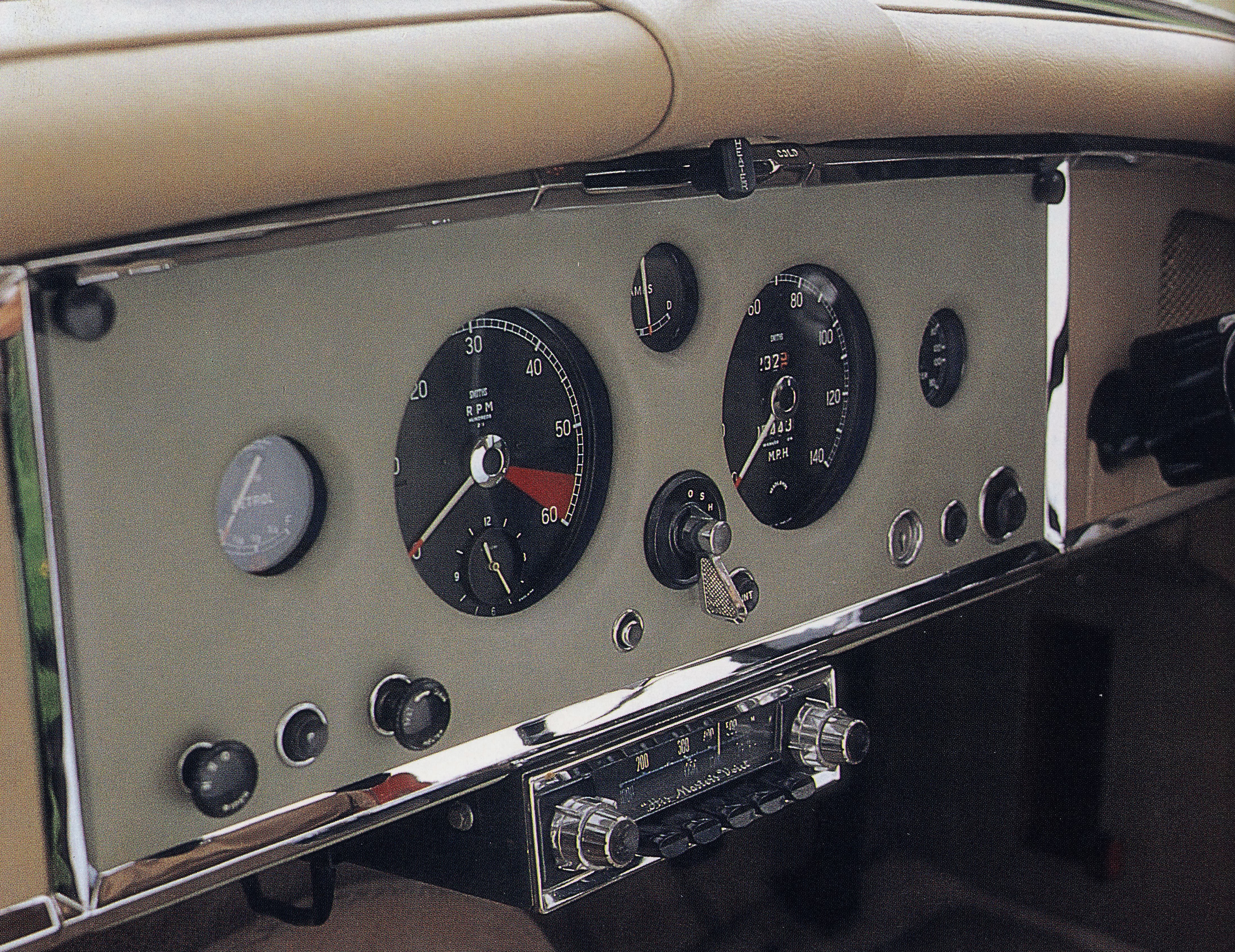
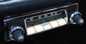
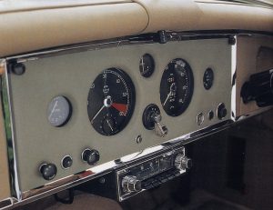 Model 500T in XK 150. Note the speaker grille mounted in the dashboard above the steering wheel Photo: Duncan Wherret, Jaguar XK 120/140/150
Model 500T (positive earth polarity only), was nearly identical to its predecessor Model 400T. In line with the 400 series portfolio, Model 501T was identical to Model 500T but had a polarity switch, whereas Model 502T had MW only (and a polarity switch).
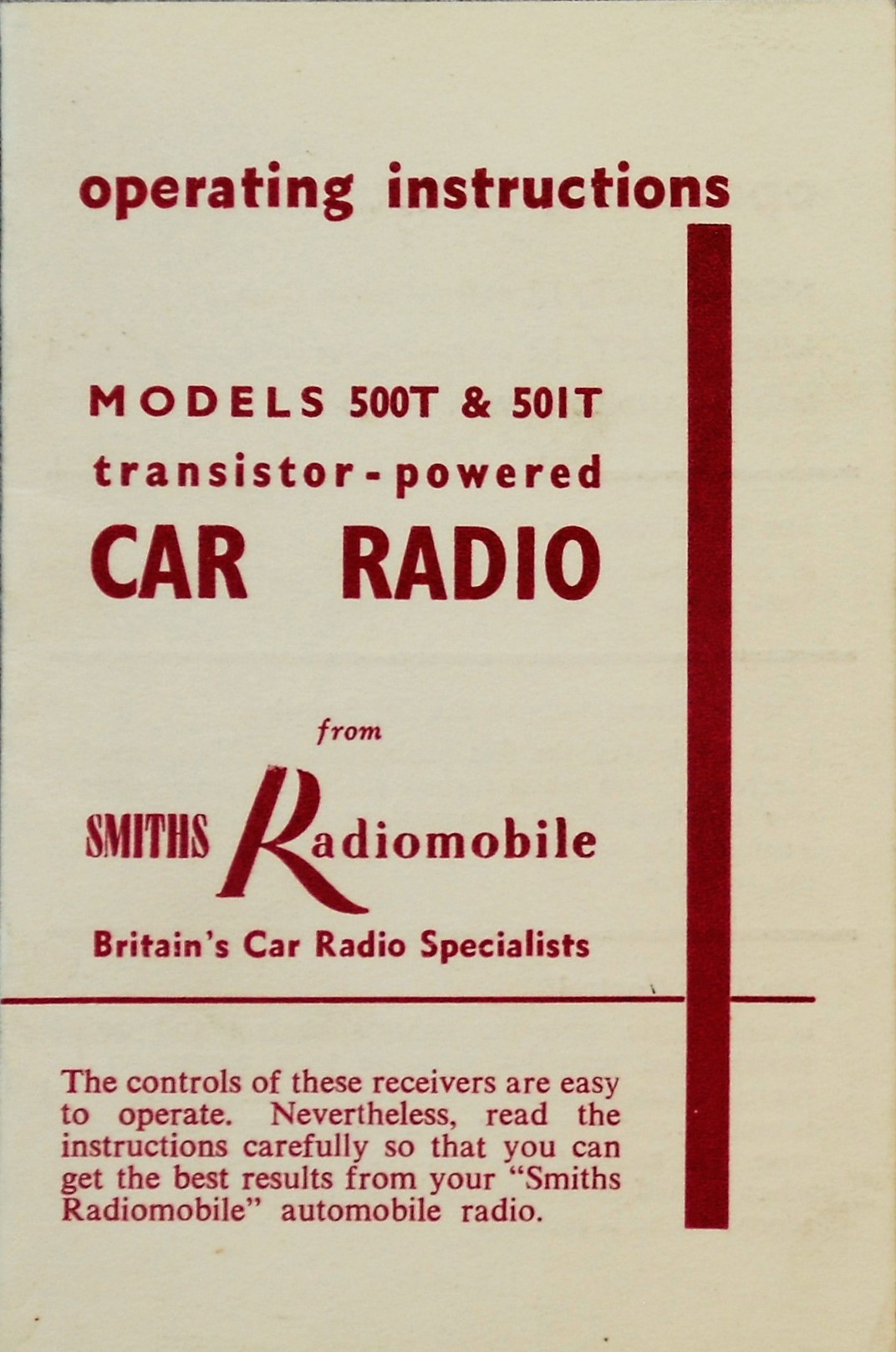
 Operating instructions for 500T and 600T. Latter shows various available models as per 500T series.
Note: 600T is “Radiomobile” and no longer HMV. Photo Roger Payne
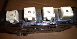
The 1961 Jaguar Mark X SPC lists yet another 500 series model: Model 530T. This is a Medium & Short Wave radio that has been coded similarly as Model 230 of the older 200 series. Although we only see one dial the whole inner scale rotates when the wavelength knob is turned. The following scales are shown: MW, 90M, 60M, 49M, 41M, 31M, 25M, 19M, and 16M. Unlike the other 500 series models the 530T model has no push buttons and is also in that respect a successor of Model 230.
Jaguar lists this version as 530TB/VA with part number C.22931 and C.24489. This model is also used on “S” series and various E-types of the Series 1.
 Model 530T with MW & SW
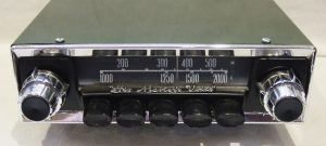
4.6 Radiomobile 50 series (1960 – 1962)
The 40 series was rather short lived as the 50 series replaced the (introduced late 1958) 40 series in 1960. Same model programme as for the 40 series with respectively Model 50T, 51T, 52T and 52TC. The 50 series had 4 valves and 2 transistors, just like the 40 series.
Model 50T is a MW and LW receiver without polarity switch (positive earth only). Note the RH turn knob for band choice with L and M. Model 51T is identical to the 50T however had a polarity switch.
Model 52T and 52TC are identical to the 51T but have Medium Wave only; Model 52TC has in addition “Tone Control”. Note that the scale of Model 52T is in MC/S (or MHz) as we have seen on Model 402T.
 Model 50T
 Model 51T with polarity switch
4.7 Amplifier units for the 400 and 500 series.
Two Amplifier units are used: the A or B Type with 1 respectively 2 transistors. Jaguar opted for the B type amplifier with code 98200B both for the 400 and 500 series with Jaguar part number 8267.
There was also a 98200K amplifier which had an additional heat sink, probably for tropical applications.
Various brackets exist for installing these Amplifiers. The bracket below has Radiomobile code RMO 3320K. Note the large transistor(s) and aluminium cooling fins.
 98200A; not recommended by Jaguar
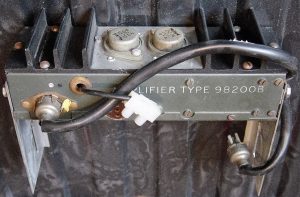 98200B as used by Jaguar
4.8 Installation of the 200, 400 and 500 series as well as 20, 40 and 50 series in the XK 150
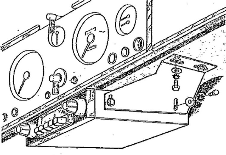
Note that the installation of the above models in the XK 150 is identical to the method described for the 200 series in the XK 140, but only using the special mounting brackets of the XK 140 OTS as the XK 150 has no wooden instrument panel. In case of Automatic versions (with the selector handle under the dashboard), extra long brackets were used to lower the receiver installation (see photos below).

 Special brackets for RM 20, 200, 202 and 230 in XK 150 Loudspeaker fitting in XK 150 dashboard
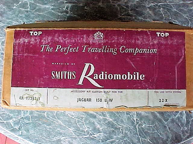
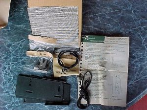 Original Smiths Radiomobile accessory kit for installation of Model 22X in XK 150 with Automatic (BW)
4.5 Typical price levels of the 20 series radio systems
The XK 150 FHC sold for around £ 1950 in the UK by Spring 1958 (in standard form), while an Optional radio was listed from £35 upwards. We notice in general that radio prices dropped as a percentage of the total cost of the car below 2%. This trend continues after the introduction of the new XK 150S when we relate the cost of optional radios to a selling price £2065 in 1958.
US selling prices for the XK 150 and XK 150 S had increased by 1958 to a level of $4550 and $5150 (respectively) for standard versions. Radio price levels (apparently) had dropped to a level around the $ 100 mark meaning the cost of an optional radio had come down to around 2% of the car price. This may also have been influenced by the introduction of “transistor” radios, gradually replacing the valve type of radio.
5. Observations and conclusions
The period 1948 to 1961 was an interesting one as we witnessed the change-over from the “vacuum radio tube” technology towards the new “semi-conductor” era. This is not only reflected in miniaturization of equipment, but also by a steady increasing performance with respect to quality of reception and sound, as well as output power for the loudspeakers.
The first Radiomobile products, starting 1946, were “individual developments” lacking an overall product portfolio approach, which is not surprising for a newly established company. These first Model 100 radios (but also the 4000 and 4200 series) received continuously new updates and derivatives were added “as the need arose”. Within this range, new low-end versions were created by simply offering less features. This also included adaptions to geographical differences, like offering “MW only” versions (e.g. no LW for USA).
By 1955 Radiomobile management introduced a new comprehensive product portfolio concept with typically two ranges: a low-end and a high-end range having each a different “platform”. This portfolio was consistently further developed into the Sixties, whereby the logic of product codes remained the same, contributing to a better and immediate market acceptance of new versions when introduced.
It is interesting to see how Radiomobile dealt with the situation regarding the “His Master’s Voice” rights in North (and South) America. The company’s initial intention was to use the HMV name and logo throughout their portfolio, which became also clear from various magazine and newspaper advertisements using the slogan: “The new HMV Car radio by Radiomobile”. However, due to the existing RCA rights in North and South America, the policy using the HMV brand and logo had to be abanded in the USA: their most important export market! The Emitron brand, chosen as a substitute, did not have the same market impact and also lead to “double branding” for most of their products.
Via an intermediate period of having HMV branding for the high-end range and Radiomobile for the low-end versions (with exception for the USA where around 1955/1956 Emitron had been replaced by Radiomobile for high-end radios as well), the company finally felt strong enough to completely omit the HMV brand in favour of using Radiomobile for all versions all over the world.